WO2012120801A1 - ステータの固定構造および駆動装置 - Google Patents
ステータの固定構造および駆動装置 Download PDFInfo
- Publication number
- WO2012120801A1 WO2012120801A1 PCT/JP2012/001154 JP2012001154W WO2012120801A1 WO 2012120801 A1 WO2012120801 A1 WO 2012120801A1 JP 2012001154 W JP2012001154 W JP 2012001154W WO 2012120801 A1 WO2012120801 A1 WO 2012120801A1
- Authority
- WO
- WIPO (PCT)
- Prior art keywords
- stator
- wire
- fixing structure
- bent
- cover
- Prior art date
- Legal status (The legal status is an assumption and is not a legal conclusion. Google has not performed a legal analysis and makes no representation as to the accuracy of the status listed.)
- Ceased
Links
Images



Classifications
-
- H—ELECTRICITY
- H02—GENERATION; CONVERSION OR DISTRIBUTION OF ELECTRIC POWER
- H02K—DYNAMO-ELECTRIC MACHINES
- H02K5/00—Casings; Enclosures; Supports
- H02K5/04—Casings or enclosures characterised by the shape, form or construction thereof
-
- H—ELECTRICITY
- H02—GENERATION; CONVERSION OR DISTRIBUTION OF ELECTRIC POWER
- H02K—DYNAMO-ELECTRIC MACHINES
- H02K1/00—Details of the magnetic circuit
- H02K1/06—Details of the magnetic circuit characterised by the shape, form or construction
- H02K1/12—Stationary parts of the magnetic circuit
- H02K1/18—Means for mounting or fastening magnetic stationary parts on to, or to, the stator structures
- H02K1/185—Means for mounting or fastening magnetic stationary parts on to, or to, the stator structures to outer stators
-
- B—PERFORMING OPERATIONS; TRANSPORTING
- B60—VEHICLES IN GENERAL
- B60L—PROPULSION OF ELECTRICALLY-PROPELLED VEHICLES; SUPPLYING ELECTRIC POWER FOR AUXILIARY EQUIPMENT OF ELECTRICALLY-PROPELLED VEHICLES; ELECTRODYNAMIC BRAKE SYSTEMS FOR VEHICLES IN GENERAL; MAGNETIC SUSPENSION OR LEVITATION FOR VEHICLES; MONITORING OPERATING VARIABLES OF ELECTRICALLY-PROPELLED VEHICLES; ELECTRIC SAFETY DEVICES FOR ELECTRICALLY-PROPELLED VEHICLES
- B60L50/00—Electric propulsion with power supplied within the vehicle
- B60L50/20—Electric propulsion with power supplied within the vehicle using propulsion power generated by humans or animals
-
- B—PERFORMING OPERATIONS; TRANSPORTING
- B62—LAND VEHICLES FOR TRAVELLING OTHERWISE THAN ON RAILS
- B62K—CYCLES; CYCLE FRAMES; CYCLE STEERING DEVICES; RIDER-OPERATED TERMINAL CONTROLS SPECIALLY ADAPTED FOR CYCLES; CYCLE AXLE SUSPENSIONS; CYCLE SIDECARS, FORECARS, OR THE LIKE
- B62K11/00—Motorcycles, engine-assisted cycles or motor scooters with one or two wheels
-
- B—PERFORMING OPERATIONS; TRANSPORTING
- B62—LAND VEHICLES FOR TRAVELLING OTHERWISE THAN ON RAILS
- B62M—RIDER PROPULSION OF WHEELED VEHICLES OR SLEDGES; POWERED PROPULSION OF SLEDGES OR SINGLE-TRACK CYCLES; TRANSMISSIONS SPECIALLY ADAPTED FOR SUCH VEHICLES
- B62M6/00—Rider propulsion of wheeled vehicles with additional source of power, e.g. combustion engine or electric motor
- B62M6/40—Rider propelled cycles with auxiliary electric motor
- B62M6/55—Rider propelled cycles with auxiliary electric motor power-driven at crank shafts parts
-
- H—ELECTRICITY
- H02—GENERATION; CONVERSION OR DISTRIBUTION OF ELECTRIC POWER
- H02K—DYNAMO-ELECTRIC MACHINES
- H02K15/00—Processes or apparatus specially adapted for manufacturing, assembling, maintaining or repairing of dynamo-electric machines
- H02K15/16—Centring rotors within the stators
-
- H—ELECTRICITY
- H02—GENERATION; CONVERSION OR DISTRIBUTION OF ELECTRIC POWER
- H02K—DYNAMO-ELECTRIC MACHINES
- H02K3/00—Details of windings
- H02K3/04—Windings characterised by the conductor shape, form or construction, e.g. with bar conductors
- H02K3/28—Layout of windings or of connections between windings
-
- H—ELECTRICITY
- H02—GENERATION; CONVERSION OR DISTRIBUTION OF ELECTRIC POWER
- H02K—DYNAMO-ELECTRIC MACHINES
- H02K3/00—Details of windings
- H02K3/32—Windings characterised by the shape, form or construction of the insulation
- H02K3/38—Windings characterised by the shape, form or construction of the insulation around winding heads, equalising connectors, or connections thereto
-
- B—PERFORMING OPERATIONS; TRANSPORTING
- B60—VEHICLES IN GENERAL
- B60L—PROPULSION OF ELECTRICALLY-PROPELLED VEHICLES; SUPPLYING ELECTRIC POWER FOR AUXILIARY EQUIPMENT OF ELECTRICALLY-PROPELLED VEHICLES; ELECTRODYNAMIC BRAKE SYSTEMS FOR VEHICLES IN GENERAL; MAGNETIC SUSPENSION OR LEVITATION FOR VEHICLES; MONITORING OPERATING VARIABLES OF ELECTRICALLY-PROPELLED VEHICLES; ELECTRIC SAFETY DEVICES FOR ELECTRICALLY-PROPELLED VEHICLES
- B60L2200/00—Type of vehicles
- B60L2200/12—Bikes
-
- Y—GENERAL TAGGING OF NEW TECHNOLOGICAL DEVELOPMENTS; GENERAL TAGGING OF CROSS-SECTIONAL TECHNOLOGIES SPANNING OVER SEVERAL SECTIONS OF THE IPC; TECHNICAL SUBJECTS COVERED BY FORMER USPC CROSS-REFERENCE ART COLLECTIONS [XRACs] AND DIGESTS
- Y02—TECHNOLOGIES OR APPLICATIONS FOR MITIGATION OR ADAPTATION AGAINST CLIMATE CHANGE
- Y02T—CLIMATE CHANGE MITIGATION TECHNOLOGIES RELATED TO TRANSPORTATION
- Y02T10/00—Road transport of goods or passengers
- Y02T10/60—Other road transportation technologies with climate change mitigation effect
- Y02T10/64—Electric machine technologies in electromobility
Definitions
- the present invention relates to a stator fixing structure and a drive device, and more particularly to a technique for fixing a stator to a housing.
- stator As a motor or a generator, one having a stator, a rotor provided on the inner circumferential side thereof, and a case for housing the stator and the rotor is known.
- the stator is fixed to the case by bolts, screws or the like (see, for example, Patent Document 1).
- it is also known to bond the stator to the case by means of an adhesive.
- the present invention has been made in view of such circumstances, and has an object of providing a stator fixing structure and a driving device capable of fixing a stator in a short time while having a simple structure.
- the present invention has the following configuration in order to achieve such an object. That is, according to the present invention, there is provided a housing including a stator, a cylindrical portion for housing the stator, a cover connected to the housing and closing an upper opening of the cylindrical portion, a wire, and an upper surface of the stator And a bent wire member provided in a state of being compressed and deformed in the axial center direction of the stator between the back surface of the cover and the stator, and the bent wire member viewed from the axial center direction. And a peak portion bent so as to project upward in the axial direction, and bent so as to project downward in the axial direction.
- the valleys are alternately and continuously formed, and the ridges are in contact with the back surface of the cover, and the valleys are a fixing structure of the stator in contact with the upper surface of the stator.
- the bending wire is made of a wire, and has a substantially annular shape in which a part is opened as viewed from the axial direction.
- the substantially ring shape includes not only a shape formed of only a curve such as a circle and an ellipse, a shape formed of a straight line such as a polygon, and a shape formed of a straight line and a curve.
- a peak portion bent to protrude upward in the axial direction and a valley portion bent to protrude downward in the axial direction are alternately and continuously formed.
- the direction from the stator toward the cover is the upper side, and the opposite direction is the lower side. Therefore, when the bending wire is viewed around the axis, the bending wire has a mountain shape or a wave shape in which peak portions and valley portions protruding in the axial direction are alternately continued.
- a peak part and a valley part may be connected linearly, and may be connected curvilinearly.
- the peak portion contacts the back surface of the cover, and the valley portion contacts the upper surface of the stator. Furthermore, the bending wire is provided in a state of being compressed and deformed in the axial direction. For this reason, the bending wire generates an elastic force that tends to expand in the axial direction. The elastic force causes the stator to receive an axial downward force. The stator is pressed against the tubular portion and held in the housing. Therefore, it is possible to preferably suppress the position of the stator from shifting in the axial direction.
- bent wire is elastically deformable, even if there are variations in the dimensions of the stator and the cover in the axial direction, the variations can be absorbed and the stator can be appropriately pressed against the cylindrical portion.
- stator fixing structure since a bolt etc. are not used in order to fix a stator, a structure can be simplified. Further, the work of fixing the stator to the housing is merely provided with a bent wire between the stator and the cover, and the workability is good. Also, the stator can be fixed in a short time.
- the axial direction is not limited to a specific direction such as the vertical direction. That is, the stator can be installed in any orientation and posture, and along with this, the axial direction can also be in any direction.
- the bent wire has a plurality of corner portions and a plurality of straight portions connecting adjacent corner portions so as to be substantially polygonal when viewed from the axial center direction.
- the outer shape of the bent wire exhibits a substantially polygonal shape in the axial direction view.
- the corner is a portion where the wire is bent, and corresponds to a vertex of a substantially polygonal shape.
- a linear part is a site
- each of the corner portions is formed in the peak portion or the valley portion.
- the wire is bent in one direction of the peak in a direction in which the bending according to the peak and the bending according to the corner are combined.
- the corner is at the same position as the valley, the wire is bent in one direction of the valley, in which the bending according to the valley and the bending according to the corner are combined. All corners are formed together with the peaks or valleys, and the corners double as peaks or valleys. The total number of peaks and valleys suffices for the number of bends in the wire regardless of the number of corners. Therefore, the forming of the bent wire can be performed relatively easily.
- the peak and the valley are further bent so that the outer shape of the bent wire is substantially polygonal with the peak and the valley as the vertex when viewed from the axial direction.
- the bent wire has a straight portion connecting the adjacent peak and valley portions.
- the peaks and valleys are bent so as to protrude in the axial direction, and are bent so as to be the apexes of the substantially polygonal shape in the axial direction.
- the shape of the bending wire basically does not change even if it is turned upside down. For example, a portion that protrudes in one of the axial directions can be treated as a peak or a valley. Therefore, the burden of the operation
- the bent wire is formed so as to be larger than the outer diameter of the stator when viewed from the axial center direction, and is assembled in a deformed state so that the outer shape becomes smaller.
- the bending wire is partially open when viewed from the axial direction, the bending wire can also be compressed and deformed radially inward in the axial direction so that the outer shape thereof becomes smaller.
- the bending wire has a substantially polygonal shape larger than the outer diameter of the stator when viewed in the axial direction, the bending wire is attached to the peripheral edge portion of the stator even when assembled in a deformed state so that the outer shape is small. And so on.
- the bent wire is made of a wire having a circular cross section. If the cross-sectional shape is a circular wire, it can be bent in any direction. Therefore, the bending wire can be formed relatively easily.
- the cover is formed on the back surface in the circumferential direction around the axis, contacts the bent wire, and receives a radially outward elastic force of the axis generated by the bent wire.
- a protruding portion which is formed to project radially inward from the side wall portion from the side wall portion, contacts the peak portion, and receives the elastic force upward in the axial direction generated by the bent wire;
- the bent wire is stretched in the circumferential direction of the side wall by the radially outward elastic force of the bent wire, and is naturally stopped at the side wall.
- the bent wire can be easily fixed to the cover.
- the bending wire can be compressed and deformed in a state of being held by the side wall portion. Therefore, if the cover is connected to the housing, the bending wire can be compressed and deformed at a predetermined position at once. Thus, the stator can be fixed to the housing very efficiently.
- the inner diameter of the side wall portion is preferably slightly larger than the outer diameter of the stator. According to this, it is possible to accommodate a part of the upper side of the stator in the side wall portion. Thus, since a part of stator can be accommodated in a cover, size reduction can be achieved easily.
- the overhanging portion is inclined downward in the axial direction toward the inside in the radial direction, and the ridge portion can be held between the overhanging portion and the side wall portion.
- a recess is formed.
- the overhanging portion which the bending wire is pushing upward in the axial direction is inclined downward in the axial direction toward the inside in the radial direction.
- the stator includes a stator core and a coil formed by winding a winding around the stator core, and the bent wire is in direct contact with the upper surface of the stator core.
- the stator core is more rigid than the coil. Since the bent wire is in direct contact with the relatively rigid stator core, the stator can be accurately pushed.
- the stator further includes a restriction member which is provided on the upper surface of the stator core and inside the outer peripheral edge of the stator core and which restricts the bending wire from moving in the radial direction.
- a restriction member which is provided on the upper surface of the stator core and inside the outer peripheral edge of the stator core and which restricts the bending wire from moving in the radial direction.
- the stator further includes an insulating bobbin provided between the stator core and the coil and covering the stator core, and the restriction member is integrally configured with the insulating bobbin.
- the insulating bobbin also serves as the regulating member, the structure can be simplified.
- the present invention has a rotor and a stator provided on the outer peripheral side of the rotor, and includes a motor for generating power, a housing including a cylindrical portion for housing the motor, and the housing coupled to the housing A cover closing the upper opening of the ring-shaped portion and a wire rod, and provided between the upper surface of the stator and the back surface of the stator in a state compressed and deformed in the axial center direction of the stator; And the bending wire has a substantially annular shape of which a part is opened as viewed from the axial direction, and protrudes upward in the axial direction. A bent peak portion and a valley portion bent so as to project downward in the axial direction are alternately and continuously formed, the peak portion contacts the back surface of the cover, and the valley portion is With the top of the stator A drive device for catalyst.
- the drive device of the present invention since the stator fixing structure described above is adopted, even if there are variations in the dimensions of the stator and the cover in the axial direction, the variations are absorbed The positional deviation of the stator in the axial direction of the stator can be suitably suppressed.
- the structure of the drive device can be simplified. Further, the operation of fixing the stator to the housing is merely provided with the bent wire between the stator and the cover, and the workability is good and can be performed in a short time. Thus, the drive device can be assembled efficiently.
- the drive unit can be mounted on a bicycle
- the housing further has a crank shaft chamber into which a crank shaft of the bicycle is inserted
- the motor is a pedal connected to the crank shaft. It is preferable to be able to generate power that assists in stepping on.
- the pedal often comes in contact with the ground first, and the crankshaft is connected to the pedal. Therefore, in a drive mounted on a bicycle, not only the housing may be directly impacted, but also the inside of the drive (crank chamber) may be directly impacted through the crankshaft. In the latter case, the force acting on the stator in the axial direction is large.
- the drive device since the above-described stator fixing structure is adopted, it is possible to preferably prevent the position of the stator from being displaced in the axial direction or to be disengaged. Therefore, according to the drive device which concerns on this invention, it can apply suitably to a bicycle.
- the peak portion of the bent wire contacts the back surface of the cover, and the valley portion of the bent wire contacts the upper surface of the stator. Furthermore, the bending wire is provided in a state of being compressed and deformed in the axial direction. For this reason, the bending wire generates an elastic force that tends to expand in the axial direction. The elastic force causes the cover to receive an axial upward force, and the stator to receive an axial downward force. The stator is pressed against the tubular portion and held in the housing. Therefore, it is possible to preferably suppress the position of the stator from shifting in the axial direction.
- bent wire is elastically deformable, even if there are variations in the dimensions of the stator and the cover in the axial direction, the variations can be absorbed and the stator can be appropriately pressed against the cylindrical portion.
- stator fixing structure since a bolt etc. are not used in order to fix a stator, a structure can be simplified. Further, the work of fixing the stator to the housing is merely provided with the bent wire between the stator and the cover, and the workability is good. Also, the stator can be fixed in a short time.
- the drive device since the stator fixing structure described above is adopted, even if there are variations in the dimensions of the stator and the cover in the axial direction, the variations are absorbed, and Deviation of the position in the axial direction of the stator can be suitably suppressed.
- the structure of the drive device can be simplified. Further, the operation of fixing the stator to the housing is merely provided with the bent wire between the stator and the cover, and the workability is good and can be performed in a short time. Thus, the drive device can be assembled efficiently.
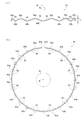
- FIG.12 (a) is a partial side view of the bending wire rod seen from the direction orthogonal to an axial center
- FIG.12 (b) is a top view of the bending wire rod seen from the axial center direction. It is a left side view of the bicycle carrying a drive.
- FIG. 1 is an external view of a drive device according to an embodiment.
- the drive device 1 includes a housing 3 and a cover 5.
- the cover 5 is fastened to the housing 3 by bolts 7.
- a crankshaft 71 of the bicycle passes through the driving device 1.
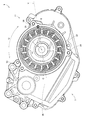
- FIG. 2 is a plan view of an essential part of the drive device 1.
- the housing 3 has a cylindrical portion 11 having a substantially cylindrical shape.
- the stator 13 is accommodated in the cylindrical portion 11.
- a spring pin 15 is press-fitted between the cylindrical portion 11 and the stator 13.
- FIG. 3 is a cross-sectional view taken along line AA of FIG.
- a rotor 16 is provided on the inner peripheral side of the stator 13.
- a rotating shaft 17 is integrally rotatably connected to the rotor 16.
- the rotating shaft 17 is rotatably supported by the housing 3.
- the stator 13, the rotor 16 and the rotating shaft 17 constitute a motor 18 that generates power.
- An output shaft 20 is interlocked and connected to the rotation shaft 17 via a gear unit 19 and the like.
- the output shaft 20 outputs the power generated by the motor 18.
- the cover 5 described above closes the upper opening of the cylindrical portion 11.
- the cover 5 is in contact with the upper end surface 27 of the cylindrical portion 11.
- a bending wire 51 is provided in a state of being compressed and deformed.
- the housing 3 has a left case 3L and a right case 3R which can be separated from each other. Below, when it is not necessary to distinguish left case 3L and right case 3R, it describes only as housing 3.
- FIG. 1 when it is not necessary to distinguish left case 3L and right case 3R, it describes only as housing 3.
- the “axial center R” is used in a unified manner, assuming that the axial center R of the stator 13 and the central axis of the cylindrical portion 11 substantially coincide with each other.
- the direction from the stator 13 toward the cover 5 in the axial direction of the stator 13 will be referred to as “axial R direction upward” or “upper”.
- the direction opposite to the direction from the stator 13 toward the cover 5 is referred to as “axial R direction downward” or “downward”.
- axial R direction upward or “upper”.
- the upper side of the drawing is referred to as “axial R direction upward” or simply “upper”, and the lower side of the drawing is referred to as “axial R direction downward” or simply “lower”.
- this does not limit the axial center R direction to a specific direction such as the vertical direction. That is, the stator 13 can be installed in any orientation and posture, and along with this, the axial center R can also be oriented in any direction.
- a direction around the axis R is called “circumferential direction Q”.
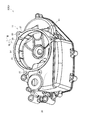
- FIG. 4 is a perspective view of an essential part of the housing 3. In FIG. 4, only the left case 3L is shown, and the right case 3R is not shown.
- the cylindrical portion 11 has an inner circumferential surface 21 inside thereof.
- the inner circumferential surface 21 has an inner diameter slightly larger than the outer diameter of the stator 13 and can accommodate the stator 13.
- a single first groove 23 is formed in the inner circumferential surface 21.
- the 1st groove part 23 is shown in the position slightly different from FIG.
- a flange portion 24 projecting inward in the radial direction of the axial center R (hereinafter, appropriately abbreviated as "radial direction") is formed.
- the inner diameter of the flange portion 24 is smaller than the outer diameter of the stator 13.
- the flange portion 24 contacts the stator 13 at its upper surface to support the stator 13.
- the cylindrical portion 11 further includes a plurality of (for example, three) boss portions 25 for connecting the cover 5.
- the housing 3 further includes a plate-like portion 29 protruding from the outer peripheral surface of the cylindrical portion 11.
- the plate-like portion 29 doubles as a wall forming a crank shaft chamber 72 into which the crank shaft 71 is inserted.
- the stator 13 has a stator core 31, an insulating bobbin 35 and a coil 37.
- the insulating bobbin 35 covers the stator core 31.
- the coil 37 is formed by a winding wound on the stator core 31 from above the insulating bobbin 35.
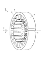
- FIG. 5 is a perspective view of an essential part of the stator. As illustrated, a second groove 33 substantially parallel to the axial center R is formed on the outer peripheral surface 32 of the stator core 31.
- the second groove 33 has a substantially semicircular shape.
- the stator core 31 further has a plurality of teeth 34. Slots F are formed between the teeth 34 adjacent to each other.
- the second groove 33 is disposed radially outside of the slot F.
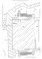
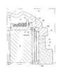
- FIGS. 6 and 7 are enlarged cross-sectional views showing the fixing structure of the stator.
- the insulating bobbin 35 has a collar 36 that extends radially outward and covers the upper surface of the stator core 31.
- the collar portion 36 is slightly smaller than the outer diameter of the stator core 31. Therefore, the peripheral edge portion 38 a of the upper surface 38 of the stator core 31 is exposed.
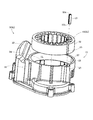
- FIG. 8 is an exploded perspective view of an essential part of the drive device 1. As illustrated, the stator 13 is attached to the cylindrical portion 11 such that the second groove 33 faces the first groove 23. Thus, a substantially circular gap is formed by the first groove 23 and the second groove 33.
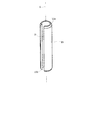
- FIG. 9 is an external perspective view of the spring pin 15.
- the spring pin 15 has a substantially cylindrical shape, and has a slit D parallel to the axis S direction.
- the upper end 15a and the lower end 15b of the spring pin 15 are chamfered and are respectively tapered.
- the spring pin 15 exerts a radially outward elastic force of the shaft core S.
- the spring pin 15 is press-fit into the space formed by the first groove 23 and the second groove 33, as shown in FIG.
- the pressed spring pin 15 is kept in a state of compressive deformation and exerts an elastic force.
- the spring pin 15 pushes the stator 13 (the stator core 31), and the portion on the opposite side of the stator 13 is pressed against the inner circumferential surface 21 of the cylindrical portion 11.
- the radial direction V from the axial center S of the spring pin 15 to the axial center R is the radial direction V
- the radial direction V intersects the inner circumferential surface 21 be the point C, centering the point C
- the stator 13 and the inner circumferential surface 21 are in surface contact with each other in a range extending on both sides in the circumferential direction Q of the axial center R.
- the inner circumferential surface 21 in surface contact with the stator 13 receives a load directed radially outward of the axial center R. Thereby, a frictional force is generated between the stator 13 and the inner circumferential surface 21.
- the stator 13 is held by this frictional force. That is, the displacement of the stator 13 in the axial center R direction is suitably suppressed.
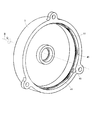
- FIG. 10 is a perspective view of the back surface of the cover 5.
- Side walls 41 are formed on the back of the cover 5.
- the side wall portion 41 is formed in the circumferential direction Q of the axial center R.
- the inner diameter of the side wall portion 41 is slightly larger than the outer diameter of the stator 13.
- the stator 13 (stator core 31) projecting from the cylindrical portion 11 is accommodated.
- the drive device 1 can be easily miniaturized.
- a notch 43 is formed in the side wall 41.
- the notch 43 is disposed at a position on the extension of the first groove 23.
- the spring pin 15 protruding upward from the upper end surface 27 of the cylindrical portion 11 is accommodated in the notch 43.
- the length of the spring pin 15 is set shorter than the dimension of the stator 13 in the axial center R direction. For this reason, the spring pin 15 does not protrude above the stator 13 (the stator core 31).
- the cover 5 further includes an overhang 45.
- the overhang portion 45 is provided so as to project radially inward from the upper end of the side wall portion 41.
- the overhanging portion 45 inclines downward in the axial center R direction toward the inside in the radial direction of the axial center R.
- annular recess (space) H is formed between the side wall portion 41 and the overhang portion 45.
- FIG. 11 is a perspective view of the bent wire 51.
- FIG. 12 (a) is a partial side view of the bent wire 51 viewed from a direction orthogonal to the axis R
- FIG. 12 (b) is a plan view of the bent wire 51 viewed from the direction of the axis R.
- 11 shows the bending wire 51 when it is not compressively deformed
- FIG. 12 shows the bending wire 51 when it is provided between the cover 5 and the stator 13 and is compressively deformed.
- the bending wire 51 consists of a single (one) wire.
- the wire preferably has a circular or substantially circular cross section.
- metals such as stainless steel, are preferable.
- As a wire round steel, a round wire, a steel wire, a round bar etc. are illustrated, for example.
- the bending wire 51 is formed by bending such a wire. Therefore, the bending wire 51 is basically configured by a portion where the wire is bent and / or a portion where the wire is linearly extended.
- the bending wire rod 51 In the bending wire rod 51, peak portions 53a bent so as to project upward in the axial center R direction and valley portions 53b bent so as to project downward in the axial center R direction are alternately formed continuously. There is.
- the bending wire 51 when viewed in the circumferential direction Q of the axial center R, the bending wire 51 has a mountain shape or a wave shape. It is preferable that the ridges 53a and the valleys 53b be arranged at substantially equal intervals.
- the ridges 53a and the valleys 53b are further bent so that the outer shape of the bent wire rod 51 becomes a substantially polygonal shape having the peaks 53a and the valleys 53b as apexes when viewed from the axial center R direction.
- the peak portion 53a is clearly surrounded by a circle, and the valley portion 53b is clearly indicated by a triangle. Therefore, the peak portion 53a and the valley portion 53b of the present embodiment also correspond to the corner portion in the present invention.
- the linear part 55 is formed between the peak part 53a and the trough part 53b which adjoin each other.
- the bending wire 51 has end portions 57a and 57b. Therefore, when viewed from the axial center R direction, the bending wire 51 has a substantially polygonal shape in which a part is opened.
- FIG. 12 (b) shows a bent wire 51 formed so as to be a regular dodecagon when viewed in the axial center R direction.
- the total of the peak part 53a corresponded to a vertex and the valley part 53b is 23 places.
- the bending wire 51 Since the bending wire 51 has the above-described shape, it can be compressed and deformed in the axial center R direction. When the bending wire 51 is compressed and deformed in the axial center R direction, the bending wire 51 expands in the axial center R direction and exerts an elastic force to return to the original shape.
- the outer shape of the bending wire 51 is a substantially polygonal shape having only the peaks 53a and the valleys 53b as the vertices, and no peaks are formed except the peaks 53a and the valleys 53b.
- the shape of the wire 51 basically does not change even if it is turned upside down. Therefore, a portion protruding in one of the axial center R directions may be treated as the peak portion 53a or may be treated as the valley portion 53b. Therefore, the burden of the operation
- the bending wire 51 since the bending wire 51 is partially opened by the end portions 57a and 57b, it can be compressed and deformed inward in the radial direction of the axial center R so that the outer shape thereof becomes small. When the bending wire 51 is compressively deformed inward in the radial direction, the bending wire 51 spreads outward in the radial direction to generate an elastic force that tends to return to the original shape.
- the bending wire 51 is formed in advance so as to have a polygonal shape larger than the outer diameter of the stator 13 when viewed from the axial center R direction. Thus, the bent wire 51 can be brought into contact with the peripheral edge 38 a of the stator 13. In the present embodiment, the bending wire 51 is further formed in advance so as to have a polygonal shape larger than the inner diameter of the side wall portion 41.
- the operation of fixing the stator 13 by the bent wire 51 is as follows. That is, as shown in FIG. 10, first, the bending wire rod 51 is compressed along the side wall portion 41 of the cover 5 so as to reduce its outer shape. Thereby, the bending wire 51 generates a radially outward elastic force, and the bending wire 51 is stretched over substantially the entire circumference of the side wall portion 41 by the elastic force. And the bending wire 51 is naturally stopped by the side wall part 41 to such an extent that it does not drop
- the cover 5 with the bent wire 51 stopped is fastened to the housing 3.
- the bending wire 51 (valley part 53b) contacts the peripheral part 38a of the stator core 31, respectively.
- the bent wires 51 peak portions 53 a) contact the overhang portions 45 in a state along the side wall portions 41.
- the bending wire 51 is compressively deformed in the axial center R direction.
- the compressively deformed bending wire 51 exerts an elastic force in the axial center R direction.
- the overhanging portion 45 receives an elastic force upward in the axial center R direction generated by the bending wire rod 51.
- the stator 13 receives an elastic force downward in the axial center R direction generated by the bent wire 51.
- stator core 31 disperses from all the valleys 53b and receives an elastic force. As a result, the lower surface of the stator core 31 is pressed against the flange portion 24 of the cylindrical portion 11, and movement of the stator 13 in the axial center R direction is suppressed.
- the task of fixing the stator 13 is only to attach the bending wire 51 to the cover 5 and to connect the cover 5 to the housing 3. Further, by connecting the cover 5 to the housing 3, the stator 13 can be fixed to the housing 3 by compressively deforming the bending wire 51 at a predetermined position at once. Therefore, the stator 13 can be fixed very efficiently in a short time.
- the bending wire 51 can be elastically deformed, even if there is variation in the dimensions of the stator 13 and the cover 5 in the axial center R direction, the variation is absorbed and the stator 13 is appropriately pressed against the cylindrical portion 11 Can.
- the fixing of the stator 13 by the spring pin 15 described above and the fixing of the stator 13 by the bent wire rod 51 are combined, and the stator 13 is more surely shifted in the axial center R direction. Can be suppressed.
- the end portions 57a and 57b on both sides of the bending wire 51 have an axial center R rather than the peak portion 53a and the valley 53b even when the bending wire 51 is compressed and deformed in the axial center R direction as described above. It is set not to protrude in the direction.
- the end portions 57a and 57b in the axial center R direction are Each position is set to always fall within the range G.
- the length from the end portion 57a to the peak portion 53a or the valley portion 53b closest to the end portion 57a is preferably shorter than the straight portion 55 between the adjacent peak portion 53a and the valley portion 53b. More preferably, the length is one third of the straight portion 55.
- the end portions 57 a and 57 b of the bending wire 51 do not contact any of the upper surface 38 of the stator core 31 and the overhanging portion 45 of the cover 5. Therefore, it can be avoided that the elastic force in the axial center R direction of the bending wire 51 changes.
- the end portions 57a and 57b of the bending wire 51 are set so as not to contact each other even when the bending wire 51 is compressed and deformed in the radial direction. Therefore, it is possible to prevent the elastic force in the axial center R direction and / or the radial direction of the bending wire 51 from changing. Incidentally, when the end portions 57a and 57b come in contact with each other, the characteristics (the relationship between the load and the elastic force) of the bending wire 51 as the elastic body change.
- the overhanging portion 45 inclines inward in the radial direction toward the axial center R direction, it can not move radially inward unless the bending wire 51 itself further contracts.
- the contact position between the bent wire 51 and the cover 5 can be preferably suppressed from being displaced in the radial direction. In other words, it is possible to preferably suppress the movement of the ridge portion 53a of the bending wire 51 inward in the radial direction.
- the collar portion 36 of the insulating bobbin 35 is slightly smaller than the outer diameter of the stator core 31, the upper surface 38 (peripheral portion 38a) of the stator core 31 is exposed. Therefore, the bending wire 51 can be in direct contact with the upper surface 38 of the stator core 31 having a relatively high rigidity. Therefore, the bending wire 51 can apply an elastic force appropriately to the stator 13, and the stator 13 can stably receive the elastic force.
- the collar part 36 is extended to the vicinity of the outer peripheral edge 39 of the stator core 31, as clearly shown in FIG. Accordingly, the flange portion 36 can suitably suppress the contact position between the bent wire 51 and the stator 13 from being displaced in the radial direction. In other words, the ridge portion 36 can preferably suppress displacement of the valley portion 53 b of the bending wire rod 51. Further, since the collar portion 36 is integrally formed with the insulating bobbin 35, the structure can be simplified.
- the bending wire 51 is made of a wire, the bending wire 51 can be suitably installed even in a narrow annular region such as the peripheral portion 38 a of the stator 13. Therefore, the stator 13 and the cover 5 can be miniaturized. Furthermore, since the bending wire 51 can be formed by bending the wire and does not require a die such as a press die, it can be manufactured inexpensively.
- the outer shape of the bending wire 51 is a polygon having a large number of apexes in the axial center R direction, the bending wire 51 can be suitably made to follow the circumferential surface formed by the side wall portion 41.
- the number of the valleys 53b is large in the bending wire 51, the force by which one valley 53b pushes the stator 13 can be made relatively small.
- the elastic force can be distributed to act on the stator 13.
- the inner diameter of the side wall portion 41 is slightly larger than the outer diameter of the stator 13, and the stator 13 (the stator core 31) protruding from the cylindrical portion 11 can be accommodated in the side wall portion 41.
- the drive device 1 since a part of the upper side of the stator 13 is accommodated in the cover 5, the drive device 1 can be easily miniaturized.
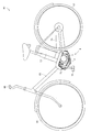
- FIG. 13 is a left side view of the bicycle 61 on which the driving device 1 is mounted.
- the bicycle 61 includes a front body 65 and a rear wheel 67 rotatably supported by the body frame 63 and a steering wheel 69 supported by the body frame 63 and steering the front wheel 65.
- the driving device 1 is supported by the vehicle body frame 63 at a lower center portion of the bicycle 61.
- the driving device 1 is provided such that the axis R is substantially horizontal.
- a crankshaft 71 is penetrated substantially horizontally in the drive unit 1.
- a pedal 73 is connected to both ends of the crankshaft 71.
- the crankshaft 71 is rotated by the pedaling force for stepping on the pedal 73.
- the rotational power of the crankshaft 71 is transmitted to the rear wheel 67 via the chain 75.
- a battery 77 for driving a motor 18 constituted by the stator 13 and the like is supported on the vehicle body frame 63.
- the crankshaft 71 is inserted into a crankshaft chamber 72 of the drive unit 1.
- the crankshaft chamber 72 is also provided with a torque sensor (not shown) for detecting the torque of the crankshaft 71 and a control unit (not shown) for controlling the motor 18.
- the power generated by the motor 18 is output to the output shaft 20.
- the rotational power output from the output shaft 20 is configured to be transmittable to the rear wheel 67 via the above-described chain 75.
- the control unit controls the motor 18 based on the detection result of the torque sensor.
- the motor 18 generates auxiliary power corresponding to the pedaling force of the pedal 73.
- the pedaling force and the power generated by the motor 18 are transmitted to the chain 75 via the crankshaft 71 and the output shaft 20, respectively.
- the chain 75 combines these treading power and power and transmits it to the rear wheel 67. Thereby, the bicycle 61 travels.
- the member that first contacts the ground is often the pedal 73.
- the crank shaft 71 is connected to the pedal 73. Therefore, in general, in the drive mounted on bicycle 61, in addition to the case where the surface of the drive (the outer surface of the housing) is directly impacted, the inside of the drive (crank chamber) is directly through the crankshaft. You may be shocked. When an impact is directly transmitted to the inside of the drive device, a large force is transmitted to the stator in the axial center R direction.
- the drive device 1 according to the present invention since the above-described fixing structure of the stator 13 is adopted, it is possible to preferably suppress the position of the stator 13 from being shifted in the axial center R direction. Therefore, according to the drive device 1 of the present embodiment, the bicycle 61 can be suitably applied.
- the present invention is not limited to the above embodiment, and can be modified as follows.
- the fixing of the stator 13 by the bending wire 51 and the fixing of the stator 13 by the spring pin 15 are used in combination, but the present invention is not limited to this. That is, the spring pin 15 may be omitted.
- the shape of a regular twenty-square shape is illustrated as the shape of the bending wire rod 51 in the axial center R direction, but the present invention is not limited to this. That is, the number of vertices of the polygonal shape can be selected and changed appropriately. For example, it may have a dodecagon shape or more. Moreover, it is not restricted to a regular polygon shape, You may change into another polygon. Alternatively, it may be changed to a circular shape, an elliptical shape or the like.
- the bending wire 51 has a substantially polygonal shape having only the peak portions 53a and the valley portions 53b as the vertices when viewed from the axial center R direction, but the present invention is limited thereto. Absent. For example, assuming that a portion corresponding to a vertex of a polygonal shape is a corner, the corner may be changed to have the peak 53a and the valley 53 separately regardless of the peak 53a and the valley 53b. Good. In other words, the corner may be formed at a position different from that of the peak portion 53a and the valley portion 53b. Alternatively, part of the ridges 53a and the valleys 53 may be changed to serve as the corner. Even in this case, corner portions provided separately from the peak portions 53a and the valley portions 53 may be included.
- each corner may be formed together with the ridges 53a, and the corners may not be formed together with the valleys 53b.
- the valleys 53b are formed between adjacent apexes (corners) and apexes (corners) of the substantially polygonal shape (i.e., substantially each side of the polygon Will be placed in the middle).
- the bending wire rod 51 was able to generate elastic power of radial direction outward, it is not restricted to this. That is, you may change suitably to the bending wire which does not generate
- the bending wire 51 is described as being a wire having a circular cross section, but the invention is not limited thereto.
- the bending wire rod 51 was stopped by the cover 5 (side wall part 41), it is not restricted to this.
- the bending wire 51 may be changed to be fixed to the cylindrical portion 11.
- the bent wire 51 may be changed to be fixed to the stator 13.
- the position at which the bent wire 51 comes in contact with the stator 13 is the peripheral portion 38 a of the stator core 31, but is not limited to this.
- the contact position may be changed to another position of the stator core 31. Also, it may be changed to be in contact with elements of the stator 13 other than the stator core 31 (for example, the insulating bobbin 35, the coil 37, etc.).
- the overhang 45 is inclined, but the invention is not limited to this. That is, the overhanging portion 45 may be changed so as to project horizontally inward in the radial direction of the axial center R.
- the collar part 36 which regulates that the bending wire 51 travels to radial inside is comprised integrally with the insulating bobbin 35, it is not restricted to this. That is, separately from the insulating bobbin 35, a restriction member may be provided to restrict the bending wire 51 from moving inward in the radial direction.
- stator 13 is illustrated as an element of the motor 18 in the above-described embodiment, the present invention is not limited to this.
- the present invention may be applied to the stator 13 that constitutes a generator.
- each configuration may be further modified as appropriate, for example, by replacing or combining with the configuration of another modified embodiment. Good.
Landscapes
- Engineering & Computer Science (AREA)
- Power Engineering (AREA)
- Mechanical Engineering (AREA)
- Transportation (AREA)
- Manufacturing & Machinery (AREA)
- Chemical & Material Sciences (AREA)
- Combustion & Propulsion (AREA)
- Insulation, Fastening Of Motor, Generator Windings (AREA)
- Iron Core Of Rotating Electric Machines (AREA)
- Motor Or Generator Frames (AREA)
- Manufacture Of Motors, Generators (AREA)
Abstract
駆動装置は、ステータ13と、ステータ13を収容する筒状部11を含むハウジング3と、ハウジング3に連結され、筒状部11の上部開口を閉塞するカバー5と、線材からなり、ステータ13の上面とカバー5の裏面との間にステータの軸心方向に圧縮変形した状態で設けられ、ステータ13を筒状部11に押しつける屈曲線材51と、を備えている。屈曲線材51は、軸心方向から見て一部が開放されている略環形状を有しており、かつ、山部、および、谷部が交互に連続して形成されており、山部はカバー5の裏面と接触し、谷部はステータ13の上面と接触する。屈曲線材51の弾性力によって、ステータ13は軸心方向下向きの力を受ける。ステータ13は筒状部11に押しつけられ、ハウジング3に保持される。
Description
この発明は、ステータの固定構造および駆動装置に係り、特に、ステータをハウジングに固定する技術に関する。
従来、モーターまたは発電機として、ステータと、その内周側に設けられるロータと、これらステータおよびロータを収容するケースとを備えているものが知られている。ステータは、ボルトやねじなどによってケースに固定されている(例えば、特許文献1参照)。固定する手法については、このほかに、接着剤によってステータをケースに接着することも知られている。
しかしながら、このような構成を有する従来例の場合には、次のような問題がある。
すなわち、ボルト等によってステータをケースに固定する構造では、ステータを固定する際にボルト等を締め付ける作業があるので組み立て時間がかかるという不都合がある。また、ステータにボルト等で固定するための部位を形成するなど、複雑な構造になるという不都合がある。他方、接着剤によって固定する手法であっても、接着剤が硬化する時間を含めると、結局、組み立て時間がかかるという不都合がある。また、作業者の手などに接着剤が付着し易く、作業性が低下し易いという不都合がある。
すなわち、ボルト等によってステータをケースに固定する構造では、ステータを固定する際にボルト等を締め付ける作業があるので組み立て時間がかかるという不都合がある。また、ステータにボルト等で固定するための部位を形成するなど、複雑な構造になるという不都合がある。他方、接着剤によって固定する手法であっても、接着剤が硬化する時間を含めると、結局、組み立て時間がかかるという不都合がある。また、作業者の手などに接着剤が付着し易く、作業性が低下し易いという不都合がある。
この発明は、このような事情に鑑みてなされたものであって、簡素な構造としつつ、短時間でステータを固定することができるステータの固定構造および駆動装置を提供することを目的とする。
この発明は、このような目的を達成するために、次のような構成をとる。
すなわち、本発明は、スステータと、前記ステータを収容する筒状部を含むハウジングと、前記ハウジングに連結され、前記筒状部の上部開口を閉塞するカバーと、線材からなり、前記ステータの上面と前記カバーの裏面との間に前記ステータの軸心方向に圧縮変形した状態で設けられ、前記ステータを前記筒状部に押しつける屈曲線材と、を備え、前記屈曲線材は、前記軸心方向から見て一部が開放されている略環形状を有しており、かつ、前記軸心方向の上方に突出するように屈曲した山部、および、前記軸心方向の下方向に突出するように屈曲した谷部が交互に連続して形成されており、前記山部は前記カバーの裏面と接触し、前記谷部は前記ステータの上面と接触するステータの固定構造である。
すなわち、本発明は、スステータと、前記ステータを収容する筒状部を含むハウジングと、前記ハウジングに連結され、前記筒状部の上部開口を閉塞するカバーと、線材からなり、前記ステータの上面と前記カバーの裏面との間に前記ステータの軸心方向に圧縮変形した状態で設けられ、前記ステータを前記筒状部に押しつける屈曲線材と、を備え、前記屈曲線材は、前記軸心方向から見て一部が開放されている略環形状を有しており、かつ、前記軸心方向の上方に突出するように屈曲した山部、および、前記軸心方向の下方向に突出するように屈曲した谷部が交互に連続して形成されており、前記山部は前記カバーの裏面と接触し、前記谷部は前記ステータの上面と接触するステータの固定構造である。
[作用・効果]屈曲線材は、線材からなり、軸心方向から見て一部が開放されている略環形状を有している。ここで、略環形状とは、円形や楕円形などの曲線のみで構成される形状のほか、多角形などの直線で構成される形状や、直線と曲線で構成される形状を含む。
また、屈曲線材は、前記軸心方向の上方に突出するように屈曲した山部、および、前記軸心方向の下方向に突出するように屈曲した谷部が交互に連続して形成されている。なお、本発明では、ステータの軸心方向のうち、ステータからカバーに向かう方向を上方とし、その反対の方向を下方とする。よって、屈曲線材を軸心回りに見ると、屈曲線材は軸心方向に突出する山部および谷部が交互に連続した山形状あるいは波状となる。なお、山部と谷部は、直線的に結ばれていてもよいし、曲線的に結ばれていてもよい。
このような屈曲線材をステータとカバーとの間に設けると、山部は、カバーの裏面と接触し、谷部はステータの上面と接触する。さらに、屈曲線材は、軸心方向に圧縮変形した状態で設けられる。このため、屈曲線材は、軸心方向に伸張しようとする弾性力を発生する。この弾性力によって、ステータは軸心方向下向きの力を受ける。ステータは筒状部に押しつけられ、ハウジングに保持される。よって、ステータの位置が軸心方向にずれることを好適に抑制することができる。
また、屈曲線材は弾性変形可能であるので、軸心方向におけるステータやカバーの寸法にばらつきがあっても、そのばらつきを吸収し、適切にステータを筒状部に押しつけることができる。
そして、このようなステータの固定構造によれば、ステータを固定するためにボルト等を用いないので、構造を簡素にすることができる。また、ハウジングにステータを固定する作業は、ステータとカバーとの間に屈曲線材を設けるだけであり、作業性が良い。また、ステータを短時間で固定することができる。
なお、軸心方向の一方を上方、軸心方向の他方を下方と規定しているが、軸心方向を鉛直方向等の特定の方向に限定するものではない。すなわち、ステータは任意の向き、姿勢で設置することができ、これに伴って軸心方向も任意の方向とすることができる。
上述した発明において、前記屈曲線材は、前記軸心方向から見て略多角形状となるように、複数の角部と、隣り合う前記角部同士を結ぶ複数の直線部とを有していることが好ましい。屈曲線材の外形状は、軸心方向視において略多角形状を呈する。角部は、線材が屈曲された部位であり、略多角形状の頂点に相当する。また、直線部は、線材が略直線状に延ばされている部位であり、上記略多角形状の辺に相当する。このような屈曲線材であれば、直線部を有しているので、外形状が曲線のみで構成される場合に比べて、屈曲線材の成形を比較的容易に行うことができる。
上述した発明において、前記角部はそれぞれ、前記山部または前記谷部に形成されていることが好ましい。たとえば、角部が山部と同じ位置である場合は、その山部の1箇所において、山部に応じた屈曲と角部に応じた屈曲とを合成した向きに線材が屈曲している。また、角部が谷部と同じ位置である場合は、その谷部の1箇所において、谷部に応じた屈曲と角部に応じた屈曲とを合成した向きに線材が屈曲している。全ての角部は山部或いは谷部と一緒に形成されており、角部が山部または谷部を兼ねる。線材が屈曲する部位の数は、角部の数に関係なく、山部および谷部の総数で足りる。よって、屈曲線材の成形を比較的容易に行うことができる。
上述した発明において、軸心方向から見て、前記屈曲線材の外形状が前記山部および前記谷部を頂点とする略多角形状となるように、前記山部および前記谷部はさらに屈曲しており、かつ、前記屈曲線材は、隣り合う前記山部および前記谷部を結ぶ直線部を有していることが好ましい。山部および谷部は、軸心方向に突出するように屈曲しつつ、軸心方向視で略多角形の頂点となるように屈曲している。このため、屈曲線材の形状は、上下を反転させても基本的に変わらない。たとえば、軸心方向の一方に突出している部位を、山部と扱うこともできるし、谷部と扱うこともできる。よって、屈曲線材を組付ける作業の負担を軽減することができる。
上述した発明において、前記屈曲線材は、前記軸心方向から見て前記ステータの外径よりも大きくなるように成形され、その外形状が小さくなるように変形した状態で組付けられていることが好ましい。屈曲線材は、軸心方向から見て一部が開放されているので、屈曲線材はその外形状が小さくなるように軸心方向の径方向内向きにも圧縮変形可能である。さらに、屈曲線材は、軸心方向から見てステータの外径よりも大きな略多角形状であるので、その外形状が小さくなるように変形した状態で組付けても、屈曲線材をステータの周縁部などに接触させることが可能である。
上述した発明において、前記屈曲線材は、円形状の断面を有する線材からなることが好ましい。断面形状が円形の線材であれば、任意の方向に屈曲させることができる。よって、比較的容易に屈曲線材を成形することができる。
上述した発明において、前記カバーは、その裏面に前記軸心回りの周方向にわたって形成され、前記屈曲線材と接触し、前記屈曲線材が発生する前記軸心の径方向外向きの弾性力を受け止める側壁部と、前記側壁部から前記軸心の径方向内側に張り出すように形成され、前記山部と接触し、前記屈曲線材が発生する前記軸心方向上向きの弾性力を受け止める張出部と、を備えていることが好ましい。これによれば、屈曲線材の径方向外向きの弾性力によって屈曲線材は側壁部の周方向にわたって突っ張り、自ずと側壁部に止められる。よって、屈曲線材をカバーに容易に止めることができる。さらに、軸心方向上向きの弾性力を受け止める張出部が側壁部から張り出しているので、屈曲線材を側壁部に止めた状態で圧縮変形させることができる。よって、カバーをハウジングに連結すれば、一挙に屈曲線材を所定位置で圧縮変形させることができる。このように、非常に効率よく、ステータをハウジングに固定することができる。
上述した発明において、前記側壁部の内径は、前記ステータの外径より若干大きいことが好ましい。これによれば、側壁部内にステータの上側の一部を収容することが可能である。このように、カバー内にステータの一部分を収容することができるので、小型化を容易に図ることができる。
上述した発明において、前記張出部は、前記径方向内側に向かって前記軸心方向下向きに傾斜しており、前記張出部と前記側壁部との間には、前記山部を保持可能な凹部が形成されていることが好ましい。屈曲線材が軸心方向上向きに押している張出部は、径方向内側に向かって軸心方向下向きに傾斜している。このような張出部によって、屈曲線材(山部)が径方向内側に移動することを抑制している。すなわち、屈曲線材とカバーとの接触位置が径方向にずれることを好適に抑制することができる。
上述した発明において、前記ステータは、ステータコアと、前記ステータコアに巻線が巻かれることにより形成されるコイルとを備え、前記屈曲線材は、前記ステータコアの上面と直接接触することが好ましい。ステータコアはコイルに比べて剛性が高い。屈曲線材は剛性の比較的に高いステータコアに直接的に接触しているので、ステータを的確に押すことができる。
上述した発明において、前記ステータは、さらに前記ステータコアの上面であって前記ステータコアの外周縁よりも内側に設けられ、前記屈曲線材が前記径方向内側に移動することを規制する規制部材を備えていることが好ましい。規制部材を備えているので、屈曲線材とステータとの接触位置が径方向にずれることを好適に抑制することができる。言い換えれば、屈曲線材の谷部がずれることを好適に抑制することができる。
上述した発明において、前記ステータは、さらに前記ステータコアと前記コイルとの間に設けられ、前記ステータコアを被覆する絶縁性ボビンを備え、前記規制部材は、前記絶縁性ボビンと一体に構成されていることが好ましい。絶縁性ボビンが規制部材を兼ねているので、構造を簡略化することができる。
また、本発明は、ロータとこのロータの外周側に設けられるステータとを有し、動力を発生するモーターと、前記モーターを収容する筒状部を含むハウジングと、前記ハウジングに連結され、前記筒状部の上部開口を閉塞するカバーと、線材からなり、前記ステータの上面と前記カバーの裏面との間に前記ステータの軸心方向に圧縮変形した状態で設けられ、前記ステータを前記筒状部に押しつける屈曲線材と、を備え、前記屈曲線材は、前記軸心方向から見て一部が開放されている略環形状を有しており、かつ、前記軸心方向の上方に突出するように屈曲した山部、および、前記軸心方向の下方向に突出するように屈曲した谷部が交互に連続して形成されており、前記山部は前記カバーの裏面と接触し、前記谷部は前記ステータの上面と接触する駆動装置である。
[作用・効果]本発明に係る駆動装置によれば、上述したステータの固定構造を採用しているので、軸心方向におけるステータやカバーの寸法にばらつきがあっても、そのばらつきを吸収して、ステータの位置がステータの軸心方向にずれることを好適に抑制することができる。また、駆動装置の構造を簡素にすることができる。さらに、ハウジングにステータを固定する作業は、屈曲線材をステータとカバーとの間に設けるだけであり、作業性が良く、短時間で行うことができる。よって、駆動装置を効率良く組み立てることができる。
上述した発明において、前記駆動装置は自転車に搭載可能であり、前記ハウジングは、さらに前記自転車のクランク軸が挿入されるクランク軸室を有し、前記モーターは、前記クランク軸に連結されるペダルの踏力を補助する動力を発生可能であることが好ましい。自転車の場合、ペダルが地面に最初に接触する場合が多く、クランク軸はこのペダルと連結されている。したがって、自転車に搭載される駆動装置においては、ハウジングが直接的に衝撃を受ける場合のみならず、クランク軸を通じて駆動装置の内部(クランク室)が直接的に衝撃を受ける場合がある。後者のような場合、ステータに対して軸心方向に働く力が大きい。しかしながら、本発明に係る駆動装置では、上述したステータの固定構造を採用しているので、ステータの位置が軸心方向にずれたり、抜けたりすることを好適に抑制することができる。よって、本発明に係る駆動装置によれば、自転車に好適に適用することができる。
本発明に係るステータの固定構造によれば、屈曲線材の山部はカバーの裏面と接触し、屈曲線材の谷部はステータの上面と接触する。さらに、屈曲線材は、軸心方向に圧縮変形した状態で設けられる。このため、屈曲線材は、軸心方向に伸張しようとする弾性力を発生する。この弾性力によって、カバーは軸心方向上向きの力を受け、ステータは軸心方向下向きの力を受ける。ステータは筒状部に押しつけられ、ハウジングに保持される。よって、ステータの位置が軸心方向にずれることを好適に抑制することができる。
さらに、屈曲線材は弾性変形可能であるので、軸心方向におけるステータやカバーの寸法にばらつきがあっても、そのばらつきを吸収し、適切にステータを筒状部に押しつけることができる。
そして、このようなステータの固定構造によれば、ステータを固定するためにボルト等を用いないので、構造を簡素にすることができる。また、ハウジングにステータを固定する作業は、屈曲線材をステータとカバーとの間に設けるだけであり、作業性が良い。また、ステータを短時間で固定することができる。
また、本発明に係る駆動装置によれば、上述したステータの固定構造を採用しているので、軸心方向におけるステータやカバーの寸法にばらつきがあっても、そのばらつきを吸収して、ステータの位置がステータの軸心方向にずれることを好適に抑制することができる。また、駆動装置の構造を簡素にすることができる。さらに、ハウジングにステータを固定する作業は、屈曲線材をステータとカバーとの間に設けるだけであり、作業性が良く、短時間で行うことができる。よって、駆動装置を効率良く組み立てることができる。
以下、図面を参照してこの発明の実施例を説明する。本実施例では、自転車に適用される駆動装置を例に採って説明する。図1は、実施例に係る駆動装置の外観図である。
1.駆動装置の全体構成
駆動装置1は、ハウジング3とカバー5を備えている。カバー5は、ハウジング3にボルト7で締結されている。駆動装置1には、自転車のクランク軸71が貫通している。
駆動装置1は、ハウジング3とカバー5を備えている。カバー5は、ハウジング3にボルト7で締結されている。駆動装置1には、自転車のクランク軸71が貫通している。
図2は駆動装置1の要部平面図である。なお、図2では、上述したカバー5、クランク軸71の他、ロータ等についても図示を省略している。図示するように、ハウジング3は、略円筒形状の筒状部11を有している。この筒状部11にはステータ13が収容されている。筒状部11とステータ13との間にはスプリングピン15が圧入されている。
図3を参照する。図3は図1のA-A矢視断面図である。図示するように、ステータ13の内周側には、ロータ16が設けられている。ロータ16には回転軸17が一体に回転可能に連結されている。回転軸17は、ハウジング3に回転可能に支持されている。これらステータ13、ロータ16および回転軸17は、動力を発生するモーター18を構成している。回転軸17には、ギアユニット19等を介して出力軸20が連動連結されている。出力軸20は、モーター18が発生する動力を出力する。
上述したカバー5は、筒状部11の上部開口を閉塞する。カバー5は、筒状部11の上端面27と接触する。カバー5とステータ13との間には、屈曲線材51が圧縮変形した状態で設けられている。
ハウジング3は、互いに分割可能な左ケース3Lと右ケース3Rとを有している。以下では、左ケース3Lと右ケース3Rを区別する必要がない場合は、単にハウジング3と記載する。
以下、各構成について説明する。なお、本実施例の説明では、便宜上、ステータ13の軸心Rと筒状部11の中心軸とは略一致するものとして、「軸心R」を統一して用いる。さらに、本実施例の説明では、便宜上、ステータ13の軸心方向のうち、ステータ13からカバー5に向かう方向を「軸心R方向上向き」または「上方」という。また、ステータ13からカバー5に向かう方向とは反対の方向を、「軸心R方向下向き」または「下方」という。例えば、図3では、図面の上側を「軸心R方向上向き」または単に「上方」と呼び、図面の下側を「軸心R方向下向き」または単に「下方」と呼ぶ。ただし、これは、軸心R方向を鉛直方向等の特定の方向に限定するものではない。すなわち、ステータ13は任意の向き、姿勢で設置することができ、これに伴って軸心R方向も任意の方向をとることができる。また、軸心R回りの方向を、「周方向Q」と呼ぶ。
2.ハウジングの構成
図4は、ハウジング3の要部斜視図である。なお、図4では、左側ケース3Lのみを図示し、右側ケース3Rの図示を省略している。
図4は、ハウジング3の要部斜視図である。なお、図4では、左側ケース3Lのみを図示し、右側ケース3Rの図示を省略している。
図示するように、筒状部11は、その内側に内周面21を有する。内周面21は、ステータ13の外径より若干大きな内径を有し、ステータ13を収容可能である。内周面21には、単一の第1溝部23が形成されている。なお、図4では、第1溝部23を図2とは若干異なる位置に示している。
これら内周面21および第1溝部23の下端には、軸心Rの径方向(以下、適宜「径方向」と略記する)内側に張り出すようなフランジ部24が形成されている。フランジ部24の内径はステータ13の外径より小さい。フランジ部24は、その上面でステータ13と接触してステータ13を支持する。
筒状部11は、さらにカバー5を連結するための複数(例えば3箇所)のボス部25を有している。ハウジング3は、さらに、筒状部11の外周面から張り出している板状部29を備えている。板状部29は、クランク軸71が挿入されるクランク軸室72を形成する壁部を兼ねている。
3.ステータの構成
図3に示すように、ステータ13は、ステータコア31と絶縁性ボビン35とコイル37とを有する。絶縁性ボビン35は、ステータコア31を被覆する。コイル37は、ステータコア31に絶縁性ボビン35の上から巻かれた巻線によって形成される。
図3に示すように、ステータ13は、ステータコア31と絶縁性ボビン35とコイル37とを有する。絶縁性ボビン35は、ステータコア31を被覆する。コイル37は、ステータコア31に絶縁性ボビン35の上から巻かれた巻線によって形成される。
図5は、ステータの要部斜視図である。図示するように、ステータコア31の外周面32には、軸心Rと略平行な第2溝部33が形成されている。第2溝部33は、略半円形状である。ステータコア31は、さらに複数のティース34を有する。隣り合うティース34の間にはそれぞれスロットFが形成されている。第2溝部33はこのスロットFの径方向外側に配置されている。
図6、図7は、それぞれステータの固定構造を示す拡大断面図である。図示するように、絶縁性ボビン35は、径方向外側に延びて、ステータコア31の上面を被覆する鍔部36を有している。鍔部36は、ステータコア31の外径よりもやや小さい。このため、ステータコア31の上面38のうち、周縁部38aは露出している。
図8は駆動装置1の要部分解斜視図である。図示するように、ステータ13は、第2溝部33が第1溝部23と向かい合うように、筒状部11に取り付けられる。これにより、第1溝部23と第2溝部33とによって略円形の空隙が形成される。
4.スプリングピンの構成
図9はスプリングピン15の外観斜視図である。図示するように、スプリングピン15は略円柱形状を有し、その軸芯S方向に平行なスリットDを有する。スプリングピン15の上端15aおよび下端15bは、面取りされており、それぞれ先細り(テーパー)となっている。スプリングピン15を軸芯Sの径方向内向きに圧縮変形させると、スプリングピン15は、その軸芯Sの径方向外向きの弾性力を発揮する。
図9はスプリングピン15の外観斜視図である。図示するように、スプリングピン15は略円柱形状を有し、その軸芯S方向に平行なスリットDを有する。スプリングピン15の上端15aおよび下端15bは、面取りされており、それぞれ先細り(テーパー)となっている。スプリングピン15を軸芯Sの径方向内向きに圧縮変形させると、スプリングピン15は、その軸芯Sの径方向外向きの弾性力を発揮する。
スプリングピン15は、図7に示すように、第1溝部23と第2溝部33とによって形成された空隙に圧入される。
図2に示すように、圧入されたスプリングピン15は、圧縮変形した状態に保たれ、弾性力を発揮する。この弾性力により、スプリングピン15はステータ13(ステータコア31)を押し、ステータ13の反対側の部分を筒状部11の内周面21に対して押しつける。具体的には、スプリングピン15の軸芯Sから軸心Rに向かう径方向を径方向Vとし、この径方向Vと内周面21が交わる点を点Cとすると、点Cを中心とし、軸心Rの周方向Q両側に広がる範囲で、ステータ13と内周面21が面接触する。
ステータ13と面接触した内周面21は、軸心Rの径方向外向きの荷重を受ける。これにより、ステータ13と内周面21との間に摩擦力が発生する。この摩擦力によってステータ13は保持される。すなわち、ステータ13が軸心R方向にずれることが好適に抑制される。
5.カバーの構成
図6、7、および図10を参照する。図10は、カバー5の裏面の斜視図である。カバー5の裏面には、側壁部41が形成されている。側壁部41は、軸心Rの周方向Qにわたって形成されている。側壁部41の内径はステータ13の外径より若干大きい。この側壁部41内に、筒状部11から突出するステータ13(ステータコア31)が収容される。このように、ステータ13の上側の一部分をカバー5内に収容するので、駆動装置1の小型化を容易に図ることができる。
図6、7、および図10を参照する。図10は、カバー5の裏面の斜視図である。カバー5の裏面には、側壁部41が形成されている。側壁部41は、軸心Rの周方向Qにわたって形成されている。側壁部41の内径はステータ13の外径より若干大きい。この側壁部41内に、筒状部11から突出するステータ13(ステータコア31)が収容される。このように、ステータ13の上側の一部分をカバー5内に収容するので、駆動装置1の小型化を容易に図ることができる。
側壁部41には切欠部43が形成されている。切欠部43は、第1溝部23の延長上の位置に配置されている。切欠部43には、図7に示すように、筒状部11の上端面27から上方に突出するスプリングピン15が収容される。このスプリングピン15の長さは、軸心R方向におけるステータ13の寸法に比べて短く設定されている。このため、スプリングピン15は、ステータ13(ステータコア31)の上方には突出しない。
カバー5は、さらに張出部45を備えている。張出部45は、側壁部41の上端から径方向内側に張り出すように設けられている。張出部45は、軸心Rの径方向内側に向かって軸心R方向下向きに傾斜している。この結果、側壁部41と張出部45との間には環状の凹部(空間)Hが形成されている。
6.屈曲線材の構成
図11を参照する。図11は屈曲線材51の斜視図である。図12(a)は軸心Rと直交する方向から見た屈曲線材51の一部側面図であり、図12(b)は軸心R方向から見た屈曲線材51の平面図である。なお、図11は、圧縮変形していないときの屈曲線材51を示し、図12は、カバー5とステータ13との間に設けられて圧縮変形しているときの屈曲線材51を示す。
図11を参照する。図11は屈曲線材51の斜視図である。図12(a)は軸心Rと直交する方向から見た屈曲線材51の一部側面図であり、図12(b)は軸心R方向から見た屈曲線材51の平面図である。なお、図11は、圧縮変形していないときの屈曲線材51を示し、図12は、カバー5とステータ13との間に設けられて圧縮変形しているときの屈曲線材51を示す。
屈曲線材51は単一(1本)の線材からなる。線材は、断面が円形または略円形であることが好ましい。線材の材質としては、ステンレスなどの金属が好ましい。線材としては、例えば、丸鋼、丸線材、鋼線、丸棒等が例示される。屈曲線材51は、このような線材を屈曲加工することによって成形される。よって、屈曲線材51は、基本的に線材が屈曲されている部位、および/または、線材が直線的に延ばされている部位によって構成されている。
図12(a)を参照する。屈曲線材51は、軸心R方向の上方に突出するように屈曲した山部53a、および、軸心R方向の下方向に突出するように屈曲した谷部53bが交互に連続して形成されている。これにより、軸心Rの周方向Q回りに見ると、屈曲線材51は山形状または波状を呈する。これら山部53aおよび谷部53bは略等間隔で配置されていることが好ましい。
図12(b)を参照する。山部53aおよび谷部53bは、軸心R方向から見て、屈曲線材51の外形状が山部53aおよび谷部53bを頂点とする略多角形状となるように、さらに屈曲している。図11および図12(b)では、山部53aを円で囲んで明示し、谷部53bを三角形で囲んで明示している。したがって、本実施例の山部53aおよび谷部53bは、この発明における角部にも相当する。
また、隣り合う山部53aおよび谷部53bの間には、直線部55が形成されている。さらに、屈曲線材51は、端部57a、57bを有している。したがって、軸心R方向から見ると、屈曲線材51は一部が開放されている略多角形状を呈する。図12(b)は、軸心R方向視で正二十四角形となるように成形された屈曲線材51を示している。なお、一部が開放されているので、頂点に相当する山部53aおよび谷部53bの総数は23箇所である。
屈曲線材51は、上述した形状を有するため、軸心R方向に圧縮変形可能である。屈曲線材51を軸心R方向に圧縮変形させると、屈曲線材51は軸心R方向に伸張して元の形状に復帰しようとする弾性力を発揮する。
このように、屈曲線材51の外形状は、全ての山部53aおよび谷部53bのみを頂点とする略多角形状であり、山部53aおよび谷部53b以外では頂点を形成していないので、屈曲線材51の形状は、上下を反転させても基本的に変わらない。したがって、軸心R方向の一方に突出している部位を、山部53aとして扱ってもよいし、谷部53bとして扱ってもよい。よって、屈曲線材51を組付ける作業の負担を軽減することができる。
また、屈曲線材51は、端部57a、57bによって一部が開放されているので、その外形状が小さくなるように軸心Rの径方向内向きに圧縮変形可能である。屈曲線材51を径方向内向きに圧縮変形させると、屈曲線材51は径方向外向きに広がって元の形状に復帰しようとする弾性力を発生する。
屈曲線材51は、予め、軸心R方向から見てステータ13の外径より大きな多角形状となるように成形されている。これにより、屈曲線材51をステータ13の周縁部38aに接触させることができる。本実施例では、屈曲線材51はさらに、側壁部41の内径より大きな多角形状となるように予め成形されている。
7.屈曲線材によるステータの固定構造
屈曲線材51によってステータ13を固定する作業は、以下の通りである。すなわち、図10に示すように、まず、その外形状が小さくなるように屈曲線材51を圧縮させつつ、カバー5の側壁部41に沿わせて設置する。これにより、屈曲線材51は径方向外向きの弾性力を発生し、この弾性力によって屈曲線材51は側壁部41の略全周にわたって突っ張る。そして、屈曲線材51は自重でカバー5から脱落しない程度に、自ずと側壁部41に止められる。
屈曲線材51によってステータ13を固定する作業は、以下の通りである。すなわち、図10に示すように、まず、その外形状が小さくなるように屈曲線材51を圧縮させつつ、カバー5の側壁部41に沿わせて設置する。これにより、屈曲線材51は径方向外向きの弾性力を発生し、この弾性力によって屈曲線材51は側壁部41の略全周にわたって突っ張る。そして、屈曲線材51は自重でカバー5から脱落しない程度に、自ずと側壁部41に止められる。
続いて、屈曲線材51を止めたカバー5をハウジング3に締結する。これにより、図6、図7に示すように、屈曲線材51(谷部53b)はそれぞれ、ステータコア31の周縁部38aに接触する。また、屈曲線材51(山部53a)はそれぞれ、側壁部41に沿った状態で張出部45に接触する。そして、屈曲線材51は軸心R方向に圧縮変形する。圧縮変形した屈曲線材51は軸心R方向に弾性力を発揮する。張出部45は、屈曲線材51が発生する軸心R方向上向きの弾性力を受け止める。また、ステータ13は、屈曲線材51が発生する軸心R方向下向きの弾性力を受ける。より詳しくは、ステータコア31は、全ての谷部53bから分散して弾性力を受ける。この結果、ステータコア31の下面が筒状部11のフランジ部24に押しつけられ、ステータ13が軸心R方向に移動することが抑制される。
このように、ステータ13を固定する作業は、屈曲線材51をカバー5に取り付けて、そのカバー5をハウジング3に連結するだけである。また、カバー5をハウジング3に連結することで、一挙に屈曲線材51を所定位置で圧縮変形させてステータ13をハウジング3に固定することができる。よって、非常に効率よく短時間でステータ13を固定することができる。
また、屈曲線材51は弾性変形可能であるので、軸心R方向におけるステータ13やカバー5の寸法にばらつきがあっても、そのばらつきを吸収し、適切にステータ13を筒状部11に押しつけることができる。
そして、本駆動装置1によれば、先に説明したスプリングピン15によるステータ13の固定と、屈曲線材51によるステータ13の固定とがあいまって、一層確実にステータ13が軸心R方向にずれることを抑制することができる。
ここで、屈曲線材51の両側の端部57a、57bは、上述したように屈曲線材51が軸心R方向に圧縮変形したときであっても、山部53aおよび谷部53bよりも軸心R方向に突出しないように設定されている。具体的には、図12(a)に示すように、軸心R方向における山部53aと谷部53bとの間の範囲を範囲Gと呼ぶと、軸心R方向における端部57a、57bの各位置はそれぞれ、範囲G内に常に収まるように設定されている。例えば、端部57aからこの端部57aに最も近い山部53a若しくは谷部53bまでの長さは、隣接する山部53aと谷部53bの間の直線部55に比べて短いことが好ましい。さらに好ましくは、その長さは直線部55の3分の1である。
このような屈曲線材51によれば、屈曲線材51の端部57a、57bは、ステータコア31の上面38およびカバー5の張出部45のいずれとも接触することがない。したがって、屈曲線材51の軸心R方向の弾性力が変化してしまうことを回避できる。
また、屈曲線材51の端部57a、57bは、上述したように屈曲線材51が径方向に圧縮変形したときであっても、互いに接触しないように設定されている。したがって、屈曲線材51の軸心R方向または/および径方向の弾性力が変化してしまうことを回避できる。ちなみに、端部57a、57bが接触してしまうと、屈曲線材51の弾性体としての特性(荷重と弾性力との関係)が変わってしまう。
また、張出部45は径方向内側に向かって軸心R方向下向きに傾斜しているので、屈曲線材51自体がさらに収縮しなければ、径方向内側に移動できない。このような張出部45によって、屈曲線材51とカバー5との接触位置が径方向にずれることを好適に抑制できる。言い換えれば、屈曲線材51の山部53aが径方向内側に移動することを好適に抑制できる。
また、絶縁性ボビン35の鍔部36はステータコア31の外径よりもやや小さいので、ステータコア31の上面38(周縁部38a)は露出している。このため、屈曲線材51は、剛性の比較的に高いステータコア31の上面38と直接的に接触することができる。よって、屈曲線材51は、ステータ13に対して弾性力を的確に作用させることができ、ステータ13は弾性力を安定して受け止めることができる。
また、鍔部36は、図6に明示されるように、ステータコア31の外周縁39の近傍まで延びている。よって、鍔部36は、屈曲線材51とステータ13との接触位置が径方向にずれることを好適に抑制できる。言い換えれば、鍔部36は、屈曲線材51の谷部53bがずれることを好適に抑制できる。また、鍔部36は絶縁性ボビン35に一体に形成されているので、構造を簡略化することができる。
また、屈曲線材51は線材からなっているので、ステータ13の周縁部38aのような幅の狭い環状の領域にも、好適に設置することができる。よって、ステータ13およびカバー5を小型化することができる。さらに、屈曲線材51は、線材を屈曲加工することによって成形することができ、プレス型などの型を必要としないので、安価に製造することができる。
また、屈曲線材51の外形状は、軸心R方向視で頂点の数が多い多角形であるので、側壁部41によって形成される円周面に屈曲線材51を好適に沿わせることができる。また、屈曲線材51は谷部53bの数が多いので、1つの谷部53bがステータ13を押す力を比較的に小さくすることができる。また、ステータ13に対して弾性力を分散して作用させることができる。
また、スプリングピン15はステータ13の上方に突出していないので、スプリングピン15が屈曲線材51と干渉することを好適に抑制することができる。
また、側壁部41の内径はステータ13の外径より若干大きく、この側壁部41内に、筒状部11から突出するステータ13(ステータコア31)を収容することができる。このように、ステータ13の上側の一部分をカバー5内に収容するので、駆動装置1の小型化を容易に図ることができる。
9.自転車への適用例
次に、本実施例の駆動装置1を自転車に適用した例を説明する。図13は駆動装置1を搭載した自転車61の左側面図である。自転車61は、車体フレーム63と車体フレーム63に回転可能に支持される前輪65および後輪67と、車体フレーム63に支持され、前輪65を操舵するハンドル69とを備えている。
次に、本実施例の駆動装置1を自転車に適用した例を説明する。図13は駆動装置1を搭載した自転車61の左側面図である。自転車61は、車体フレーム63と車体フレーム63に回転可能に支持される前輪65および後輪67と、車体フレーム63に支持され、前輪65を操舵するハンドル69とを備えている。
駆動装置1は、自転車61の略中央下部において車体フレーム63に支持されている。駆動装置1は、軸心Rが略水平となるように設けられている。駆動装置1にはクランク軸71が略水平に貫通されている。クランク軸71の両端には、ペダル73が連結されている。ペダル73を踏む踏力によってクランク軸71は回転する。クランク軸71の回転動力は、チェーン75を介して後輪67に伝達される。また、車体フレーム63には、ステータ13等で構成されるモーター18を駆動するためのバッテリー77が支持されている。
図3を参照する。クランク軸71は、駆動装置1のクランク軸室72に挿入されている。クランク軸室72には、このほかに、クランク軸71のトルクを検出するトルクセンサ(図示省略)や、モーター18を制御するための制御部(図示省略)が設けられている。モーター18が発生した動力は、出力軸20に出力される。出力軸20が出力する回転動力は、上述したチェーン75を介して後輪67に伝達可能に構成されている。
そして、制御部は、トルクセンサの検出結果に基づいてモーター18を制御する。モーター18はペダル73の踏力に応じた補助動力を発生させる。そして、踏力およびモーター18が発生する動力は、それぞれクランク軸71および出力軸20を介してチェーン75に伝達される。チェーン75は、これら踏力および動力を合成し、後輪67に伝達する。これにより、自転車61が走行する。
ここで、自転車61の場合、地面に最初に接触する部材はペダル73であることが多い。ペダル73にはクランク軸71が連結されている。したがって、一般に、自転車61に搭載される駆動装置においては、駆動装置の表面(ハウジングの外面)が直接的に衝撃を受ける場合のほか、クランク軸を通じて駆動装置の内部(クランク室)が直接的に衝撃を受ける場合がある。駆動装置の内部に衝撃が直接的に伝わると、ステータに対して軸心R方向に大きな力が伝わる。しかしながら、本発明に係る駆動装置1では、上述したステータ13の固定構造を採用しているので、ステータ13の位置が軸心R方向にずれることを好適に抑制することができる。よって、本実施例の駆動装置1によれば、自転車61に好適に適用することができる。
この発明は、上記実施形態に限られることはなく、下記のように変形実施することができる。
(1)上述した実施例では、屈曲線材51によるステータ13の固定と、スプリングピン15によるステータ13の固定とを併用したが、これに限られない。すなわち、スプリングピン15を省略してもよい。
(2)上述した実施例では、屈曲線材51の軸心R方向視の形状として、正二十四角形状を例示したが、これに限られない。すなわち、多角形状の頂点の数は適宜に選択変更することができる。例えば、十二角形状以上であってもよい。また、正多角形状に限られず、それ以外の多角形に変更してもよい。あるいは、円形状や楕円形状等に変更してもよい。
(3)上述した実施例では、屈曲線材51は、軸心R方向から見て、全ての山部53aおよび谷部53bのみを頂点とする略多角形状を有していたが、これに限られない。例えば、多角形状の頂点に相当する部位を角部とすると、この角部を、山部53aおよび谷部53bと関係なく、山部53aおよび谷部53とは別個に備えるように変更してもよい。言い換えれば、角部を、山部53aおよび谷部53bとは異なる位置に形成してもよい。あるいは、山部53aおよび谷部53の一部が角部を兼ねるように変更してもよい。この場合であっても、山部53aおよび谷部53とは別個に設けた角部を含んでいてもよい。
また、例えば、山部53aおよび谷部53bの一方のみが角部を兼ね、他方は角部を兼ねないように変更してもよい。たとえば、各角部をそれぞれ山部53aと一緒に形成するとともに、角部を谷部53bと一緒に形成しないように構成してもよい。この場合、屈曲線材51を軸心R方向から見たとき、谷部53bは、略多角形状の隣り合う頂点(角部)と頂点(角部)の間(すなわち、多角形状の各辺の略中央)に配置されることになる。
(4)上述した実施例では、屈曲線材51は径方向外向きの弾性力を発生可能であったが、これに限られない。すなわち、径方向外向きの弾性力を発生しない屈曲線材に適宜に変更してもよい。
(5)上述した実施例では、屈曲線材51は、円形状の断面を有する線材からなると説明したがこれに限られない。たとえば、矩形形状の断面を有する線材からなる屈曲線材に変更してもよい。
(6)上述した実施例では、屈曲線材51はカバー5(側壁部41)に止められていたが、これに限られない。例えば、屈曲線材51を筒状部11に止めるように変更してもよい。あるいは、屈曲線材51をステータ13に止めるように変更してもよい。
(7)上述した実施例では、屈曲線材51がステータ13と接触する位置は、ステータコア31の周縁部38aであったがこれに限られない。接触位置を、ステータコア31の別の位置に変更してもよい。また、ステータコア31以外のステータ13の要素(例えば、絶縁性ボビン35やコイル37など)と接触するように変更してもよい。
(8)上述した実施例では、張出部45は傾斜していたが、これに限られない。すなわち、張出部45は、軸心Rの径方向内側に向かって水平に張り出すように変更してもよい。
(9)上述した実施例では、屈曲線材51が径方向内側に移動することを規制する鍔部36が絶縁性ボビン35と一体に構成されていたが、これに限られない。すなわち、絶縁性ボビン35とは別個に、屈曲線材51が径方向内側に移動することを規制する規制部材を備えるように変更してもよい。
(10)上述した実施例では、自転車に適用される駆動装置1を説明したが、これに限られず、任意の装置に駆動装置1を適用してもよい。この変更に伴って、クランク軸室72を省略するように変更してもよい。
(11)上述した実施例では、ステータ13はモーター18の要素として例示したが、これに限られない。たとえば、発電機を構成するステータ13に本発明を適用してもよい。
(12)上述した実施例および上記(1)から(11)で説明した各変形実施例については、さらに各構成を他の変形実施例の構成に置換または組み合わせるなどして適宜に変更してもよい。
1 … 駆動装置
3 … ハウジング
5 … カバー
11 … 筒状部
13 … ステータ
15 … スプリングピン
16 … ロータ
18 … モーター
24 … フランジ部
31 … ステータコア
32 … 外周面
35 … 絶縁性ボビン
36 … 鍔部
37 … コイル
38 … 上面
38a … 周縁部
39 … 外周縁
41 … 側壁部
45 … 張出部
51 … 屈曲線材
53a … 山部(角部を兼ねる)
53b … 谷部(角部を兼ねる)
55 … 直線部
57a、57b …端部
61 … 自転車
71 … クランク軸
72 … クランク軸室
73 … ペダル
G … 範囲
H … 凹部(空間)
Q … 周方向
R … ステータの軸心
S … スプリングピンの軸芯
V … スプリングピンの軸芯からステータの軸心に向かう方向
3 … ハウジング
5 … カバー
11 … 筒状部
13 … ステータ
15 … スプリングピン
16 … ロータ
18 … モーター
24 … フランジ部
31 … ステータコア
32 … 外周面
35 … 絶縁性ボビン
36 … 鍔部
37 … コイル
38 … 上面
38a … 周縁部
39 … 外周縁
41 … 側壁部
45 … 張出部
51 … 屈曲線材
53a … 山部(角部を兼ねる)
53b … 谷部(角部を兼ねる)
55 … 直線部
57a、57b …端部
61 … 自転車
71 … クランク軸
72 … クランク軸室
73 … ペダル
G … 範囲
H … 凹部(空間)
Q … 周方向
R … ステータの軸心
S … スプリングピンの軸芯
V … スプリングピンの軸芯からステータの軸心に向かう方向
Claims (14)
- ステータと、
前記ステータを収容する筒状部を含むハウジングと、
前記ハウジングに連結され、前記筒状部の上部開口を閉塞するカバーと、
線材からなり、前記ステータの上面と前記カバーの裏面との間に前記ステータの軸心方向に圧縮変形した状態で設けられ、前記ステータを前記筒状部に押しつける屈曲線材と、
を備え、
前記屈曲線材は、前記軸心方向から見て一部が開放されている略環形状を有しており、かつ、前記軸心方向の上方に突出するように屈曲した山部、および、前記軸心方向の下方向に突出するように屈曲した谷部が交互に連続して形成されており、
前記山部は前記カバーの裏面と接触し、
前記谷部は前記ステータの上面と接触するステータの固定構造。 - 請求項1に記載のステータの固定構造において、
前記屈曲線材は、前記軸心方向から見て略多角形状となるように、複数の角部と、隣り合う前記角部同士を結ぶ複数の直線部とを有しているステータの固定構造。 - 請求項2に記載のステータの固定構造において、
前記角部はそれぞれ、前記山部または前記谷部に形成されているステータの固定構造。 - 請求項1に記載のステータの固定構造において、
軸心方向から見て、前記屈曲線材の外形状が前記山部および前記谷部を頂点とする略多角形状となるように、前記山部および前記谷部はさらに屈曲しており、
かつ、前記屈曲線材は、隣り合う前記山部および前記谷部を結ぶ直線部を有しているステータの固定構造。 - 請求項1から請求項4のいずれかに記載のステータの固定構造において、
前記屈曲線材は、前記軸心方向から見て前記ステータの外径よりも大きくなるように成形され、その外形状が小さくなるように変形した状態で組付けられているステータの固定構造。 - 請求項1から請求項5のいずれかに記載のステータの固定構造において、
前記屈曲線材は、円形状の断面を有する線材からなるステータの固定構造。 - 請求項1から請求項6のいずれかに記載のステータの固定構造において、
前記カバーは、
その裏面に前記軸心回りの周方向にわたって形成され、前記屈曲線材と接触し、前記屈曲線材が発生する前記軸心の径方向外向きの弾性力を受け止める側壁部と、
前記側壁部から前記軸心の径方向内側に張り出すように形成され、前記山部と接触し、前記屈曲線材が発生する前記軸心方向上向きの弾性力を受け止める張出部と、
を備えているステータの固定構造。 - 請求項7に記載のステータの固定構造において、
前記側壁部の内径は、前記ステータの外径より若干大きいステータの固定構造。 - 請求項7または請求項8に記載のステータの固定構造において、
前記張出部は、前記径方向内側に向かって前記軸心方向下向きに傾斜しており、
前記張出部と前記側壁部との間には、前記山部を保持可能な凹部が形成されているステータの固定構造。 - 請求項1から請求項9のいずれかに記載のステータの固定構造において、
前記ステータは、ステータコアと、前記ステータコアに巻線が巻かれることにより形成されるコイルとを備え、
前記屈曲線材は、前記ステータコアの上面と直接接触するステータの固定構造。 - 請求項10に記載のステータの固定構造において、
前記ステータは、さらに前記ステータコアの上面であって前記ステータコアの外周縁よりも内側に設けられ、前記屈曲線材が前記径方向内側に移動することを規制する規制部材を備えているステータの固定構造。 - 請求項10または請求項11に記載のステータの固定構造において、
前記ステータは、さらに前記ステータコアと前記コイルとの間に設けられ、前記ステータコアを被覆する絶縁性ボビンを備え、
前記規制部材は、前記絶縁性ボビンと一体に構成されているステータの固定構造。 - ロータとこのロータの外周側に設けられるステータとを有し、動力を発生するモーターと、
前記モーターを収容する筒状部を含むハウジングと、
前記ハウジングに連結され、前記筒状部の上部開口を閉塞するカバーと、
線材からなり、前記ステータの上面と前記カバーの裏面との間に前記ステータの軸心方向に圧縮変形した状態で設けられ、前記ステータを前記筒状部に押しつける屈曲線材と、
を備え、
前記屈曲線材は、前記軸心方向から見て一部が開放されている略環形状を有しており、かつ、前記軸心方向の上方に突出するように屈曲した山部、および、前記軸心方向の下方向に突出するように屈曲した谷部が交互に連続して形成されており、
前記山部は前記カバーの裏面と接触し、
前記谷部は前記ステータの上面と接触する駆動装置。 - 請求項13に記載の駆動装置において、
前記駆動装置は自転車に搭載可能であり、
前記ハウジングは、さらに前記自転車のクランク軸が挿入されるクランク軸室を有し、
前記モーターは、前記クランク軸に連結されるペダルの踏力を補助する動力を発生可能である駆動装置。
Priority Applications (5)
| Application Number | Priority Date | Filing Date | Title |
|---|---|---|---|
| EP12755553.0A EP2685604B1 (en) | 2011-03-09 | 2012-02-21 | Stator anchoring structure and drive device |
| CN201280012263.3A CN103415980B (zh) | 2011-03-09 | 2012-02-21 | 定子的固定构造以及驱动装置 |
| US14/003,291 US9236774B2 (en) | 2011-03-09 | 2012-02-21 | Stator-fixed structure and driving unit |
| EP19197988.9A EP3605795B1 (en) | 2011-03-09 | 2012-02-21 | Stator fixation structure and driving unit |
| US14/959,044 US9496763B2 (en) | 2011-03-09 | 2015-12-04 | Stator-fixed structure and driving unit |
Applications Claiming Priority (2)
| Application Number | Priority Date | Filing Date | Title |
|---|---|---|---|
| JP2011051685A JP5603810B2 (ja) | 2011-03-09 | 2011-03-09 | ステータの固定構造および駆動装置 |
| JP2011-051685 | 2011-03-09 |
Related Child Applications (2)
| Application Number | Title | Priority Date | Filing Date |
|---|---|---|---|
| US14/003,291 A-371-Of-International US9236774B2 (en) | 2011-03-09 | 2012-02-21 | Stator-fixed structure and driving unit |
| US14/959,044 Continuation US9496763B2 (en) | 2011-03-09 | 2015-12-04 | Stator-fixed structure and driving unit |
Publications (1)
| Publication Number | Publication Date |
|---|---|
| WO2012120801A1 true WO2012120801A1 (ja) | 2012-09-13 |
Family
ID=46797777
Family Applications (1)
| Application Number | Title | Priority Date | Filing Date |
|---|---|---|---|
| PCT/JP2012/001154 Ceased WO2012120801A1 (ja) | 2011-03-09 | 2012-02-21 | ステータの固定構造および駆動装置 |
Country Status (6)
| Country | Link |
|---|---|
| US (2) | US9236774B2 (ja) |
| EP (2) | EP3605795B1 (ja) |
| JP (1) | JP5603810B2 (ja) |
| CN (2) | CN105553138B (ja) |
| TW (2) | TWI443943B (ja) |
| WO (1) | WO2012120801A1 (ja) |
Families Citing this family (10)
| Publication number | Priority date | Publication date | Assignee | Title |
|---|---|---|---|---|
| JP5603810B2 (ja) * | 2011-03-09 | 2014-10-08 | ヤマハモーターエレクトロニクス株式会社 | ステータの固定構造および駆動装置 |
| JP6370736B2 (ja) | 2015-03-31 | 2018-08-08 | 株式会社シマノ | 自転車用ドライブユニット、および、このドライブユニットを備える自転車 |
| JP6514995B2 (ja) * | 2015-08-31 | 2019-05-15 | 株式会社シマノ | 自転車用ガードおよびこれを備えるドライブユニット |
| JP6721403B2 (ja) * | 2016-04-28 | 2020-07-15 | ヤマハ発動機株式会社 | 電動補助自転車 |
| USD936105S1 (en) * | 2018-06-15 | 2021-11-16 | Fukuta Electric & Machinery Co., Ltd. | Motor assembly for an electric scooter |
| USD936106S1 (en) * | 2019-03-12 | 2021-11-16 | Fukuta Electric & Machinery Co., Ltd. | Motor assembly for an electric scooter |
| DE102019215563A1 (de) * | 2019-10-10 | 2021-04-15 | Zf Friedrichshafen Ag | Stator einer elektrischen Maschine |
| FR3103653A1 (fr) * | 2019-11-22 | 2021-05-28 | Valeo Equipements Electriques Moteur | Machine électrique tournante avec blocage axial du stator |
| CN113036977B (zh) * | 2019-12-24 | 2025-09-05 | 广东德昌电机有限公司 | 泵及其电机定子 |
| JP1684126S (ja) * | 2020-09-30 | 2021-04-26 |
Citations (4)
| Publication number | Priority date | Publication date | Assignee | Title |
|---|---|---|---|---|
| JPH0326250U (ja) * | 1989-07-21 | 1991-03-18 | ||
| JPH05137290A (ja) * | 1991-11-12 | 1993-06-01 | Mitsubishi Electric Corp | 車両用交流発電機 |
| JPH0670523A (ja) | 1992-08-19 | 1994-03-11 | Matsushita Electric Ind Co Ltd | ブラシレスモータ |
| JP2004048925A (ja) * | 2002-07-12 | 2004-02-12 | Toyota Motor Corp | ステータの固定方法及び固定構造並びにロータの固定方法及び固定構造 |
Family Cites Families (14)
| Publication number | Priority date | Publication date | Assignee | Title |
|---|---|---|---|---|
| US2154146A (en) * | 1935-09-02 | 1939-04-11 | John Edward Becker | Electric motor, dynamo, and the like |
| JPS57186937A (en) | 1982-04-28 | 1982-11-17 | Toshiba Corp | Stator for electric rotary machine |
| US5315200A (en) * | 1992-07-16 | 1994-05-24 | Ford Motor Company | Electrical motor stator installation |
| JP2001507908A (ja) | 1997-11-07 | 2001-06-12 | コーニンクレッカ フィリップス エレクトロニクス エヌ ヴィ | 画像シーケンスの符号化 |
| US6100615A (en) * | 1998-05-11 | 2000-08-08 | Birkestrand; Orville J. | Modular motorized electric wheel hub assembly for bicycles and the like |
| JP3998118B2 (ja) * | 2000-10-10 | 2007-10-24 | 本田技研工業株式会社 | 電動車両 |
| WO2003084025A1 (en) * | 2002-04-01 | 2003-10-09 | Nissan Motor Co., Ltd. | Stator mounting for a double rotor electric motor |
| JP2005335536A (ja) * | 2004-05-27 | 2005-12-08 | Sanyo Electric Co Ltd | 電動車輪用ハブユニット及び該ハブユニットを具えた乗物 |
| MY148155A (en) * | 2005-10-24 | 2013-03-15 | Panasonic Corp | Capacitor motor and process for producing the same |
| CN101501959B (zh) * | 2006-06-02 | 2012-05-09 | 博泽汽车部件有限公司及两合公司,乌茨堡 | 电机和用于制造机动车致动器驱动装置的电机的方法 |
| JP2008271747A (ja) * | 2007-04-24 | 2008-11-06 | Asmo Co Ltd | 回転電機及びワッシャ部材 |
| JP4527145B2 (ja) * | 2007-11-12 | 2010-08-18 | 三菱電機株式会社 | 電動パワーステアリング装置用モータ |
| JP2010178469A (ja) * | 2009-01-28 | 2010-08-12 | Calsonic Kansei Corp | モータ |
| JP5603810B2 (ja) * | 2011-03-09 | 2014-10-08 | ヤマハモーターエレクトロニクス株式会社 | ステータの固定構造および駆動装置 |
-
2011
- 2011-03-09 JP JP2011051685A patent/JP5603810B2/ja active Active
-
2012
- 2012-02-21 US US14/003,291 patent/US9236774B2/en active Active
- 2012-02-21 EP EP19197988.9A patent/EP3605795B1/en active Active
- 2012-02-21 EP EP12755553.0A patent/EP2685604B1/en active Active
- 2012-02-21 CN CN201610096390.6A patent/CN105553138B/zh active Active
- 2012-02-21 WO PCT/JP2012/001154 patent/WO2012120801A1/ja not_active Ceased
- 2012-02-21 CN CN201280012263.3A patent/CN103415980B/zh active Active
- 2012-03-07 TW TW101107775A patent/TWI443943B/zh active
- 2012-03-07 TW TW103120391A patent/TWI488411B/zh active
-
2015
- 2015-12-04 US US14/959,044 patent/US9496763B2/en active Active
Patent Citations (4)
| Publication number | Priority date | Publication date | Assignee | Title |
|---|---|---|---|---|
| JPH0326250U (ja) * | 1989-07-21 | 1991-03-18 | ||
| JPH05137290A (ja) * | 1991-11-12 | 1993-06-01 | Mitsubishi Electric Corp | 車両用交流発電機 |
| JPH0670523A (ja) | 1992-08-19 | 1994-03-11 | Matsushita Electric Ind Co Ltd | ブラシレスモータ |
| JP2004048925A (ja) * | 2002-07-12 | 2004-02-12 | Toyota Motor Corp | ステータの固定方法及び固定構造並びにロータの固定方法及び固定構造 |
Also Published As
| Publication number | Publication date |
|---|---|
| TWI443943B (zh) | 2014-07-01 |
| US20130341112A1 (en) | 2013-12-26 |
| US20160087504A1 (en) | 2016-03-24 |
| TW201438381A (zh) | 2014-10-01 |
| EP2685604A1 (en) | 2014-01-15 |
| CN105553138B (zh) | 2018-09-28 |
| TWI488411B (zh) | 2015-06-11 |
| CN105553138A (zh) | 2016-05-04 |
| EP3605795B1 (en) | 2020-11-11 |
| EP3605795A1 (en) | 2020-02-05 |
| US9496763B2 (en) | 2016-11-15 |
| US9236774B2 (en) | 2016-01-12 |
| CN103415980A (zh) | 2013-11-27 |
| JP5603810B2 (ja) | 2014-10-08 |
| TW201251281A (en) | 2012-12-16 |
| CN103415980B (zh) | 2016-03-30 |
| JP2012191714A (ja) | 2012-10-04 |
| EP2685604A4 (en) | 2016-03-09 |
| EP2685604B1 (en) | 2019-11-27 |
Similar Documents
| Publication | Publication Date | Title |
|---|---|---|
| JP5603810B2 (ja) | ステータの固定構造および駆動装置 | |
| US7800265B2 (en) | Motor for an electric power steering apparatus | |
| JP5787080B2 (ja) | 電動パワーステアリング装置 | |
| JP5197174B2 (ja) | 波動減速機付きモータ | |
| US20190382047A1 (en) | Power steering apparatus | |
| JP4360424B2 (ja) | 駆動力伝動機構、画像形成装置及びその組み付け方法 | |
| JP2018043658A (ja) | ステアリング装置 | |
| JP2017528099A (ja) | アクチュエーター及びこれを有する電子機器 | |
| JP5603809B2 (ja) | ステータの固定構造および駆動装置 | |
| JP2017147857A (ja) | コントローラ付モータおよび減速機付モータ | |
| WO2019087456A1 (ja) | アウターロータ型回転電機 | |
| JP2018039391A (ja) | ステアリング装置の製造方法 | |
| JP2017147867A (ja) | ロータおよびモータ | |
| JP2004222373A (ja) | 小形インナーロータ型モータのヨーク構造 | |
| KR20180057289A (ko) | 스텝 액츄에이터 및 이를 포함하는 전자기기 | |
| JP2008286284A (ja) | 電動式ブレーキ装置 |
Legal Events
| Date | Code | Title | Description |
|---|---|---|---|
| WWE | Wipo information: entry into national phase |
Ref document number: 201280012263.3 Country of ref document: CN |
|
| 121 | Ep: the epo has been informed by wipo that ep was designated in this application |
Ref document number: 12755553 Country of ref document: EP Kind code of ref document: A1 |
|
| WWE | Wipo information: entry into national phase |
Ref document number: 14003291 Country of ref document: US |
|
| NENP | Non-entry into the national phase |
Ref country code: DE |
|
| WWE | Wipo information: entry into national phase |
Ref document number: 2012755553 Country of ref document: EP |