WO2012120844A1 - Vanne de régulation - Google Patents
Vanne de régulation Download PDFInfo
- Publication number
- WO2012120844A1 WO2012120844A1 PCT/JP2012/001413 JP2012001413W WO2012120844A1 WO 2012120844 A1 WO2012120844 A1 WO 2012120844A1 JP 2012001413 W JP2012001413 W JP 2012001413W WO 2012120844 A1 WO2012120844 A1 WO 2012120844A1
- Authority
- WO
- WIPO (PCT)
- Prior art keywords
- valve
- proportional valve
- control
- refrigerant
- proportional
- Prior art date
- Legal status (The legal status is an assumption and is not a legal conclusion. Google has not performed a legal analysis and makes no representation as to the accuracy of the status listed.)
- Ceased
Links
Images



Classifications
-
- F—MECHANICAL ENGINEERING; LIGHTING; HEATING; WEAPONS; BLASTING
- F16—ENGINEERING ELEMENTS AND UNITS; GENERAL MEASURES FOR PRODUCING AND MAINTAINING EFFECTIVE FUNCTIONING OF MACHINES OR INSTALLATIONS; THERMAL INSULATION IN GENERAL
- F16K—VALVES; TAPS; COCKS; ACTUATING-FLOATS; DEVICES FOR VENTING OR AERATING
- F16K11/00—Multiple-way valves, e.g. mixing valves; Pipe fittings incorporating such valves
- F16K11/02—Multiple-way valves, e.g. mixing valves; Pipe fittings incorporating such valves with all movable sealing faces moving as one unit
- F16K11/06—Multiple-way valves, e.g. mixing valves; Pipe fittings incorporating such valves with all movable sealing faces moving as one unit comprising only sliding valves, i.e. sliding closure elements
- F16K11/065—Multiple-way valves, e.g. mixing valves; Pipe fittings incorporating such valves with all movable sealing faces moving as one unit comprising only sliding valves, i.e. sliding closure elements with linearly sliding closure members
- F16K11/07—Multiple-way valves, e.g. mixing valves; Pipe fittings incorporating such valves with all movable sealing faces moving as one unit comprising only sliding valves, i.e. sliding closure elements with linearly sliding closure members with cylindrical slides
- F16K11/0716—Multiple-way valves, e.g. mixing valves; Pipe fittings incorporating such valves with all movable sealing faces moving as one unit comprising only sliding valves, i.e. sliding closure elements with linearly sliding closure members with cylindrical slides with fluid passages through the valve member
-
- F—MECHANICAL ENGINEERING; LIGHTING; HEATING; WEAPONS; BLASTING
- F16—ENGINEERING ELEMENTS AND UNITS; GENERAL MEASURES FOR PRODUCING AND MAINTAINING EFFECTIVE FUNCTIONING OF MACHINES OR INSTALLATIONS; THERMAL INSULATION IN GENERAL
- F16K—VALVES; TAPS; COCKS; ACTUATING-FLOATS; DEVICES FOR VENTING OR AERATING
- F16K11/00—Multiple-way valves, e.g. mixing valves; Pipe fittings incorporating such valves
- F16K11/02—Multiple-way valves, e.g. mixing valves; Pipe fittings incorporating such valves with all movable sealing faces moving as one unit
- F16K11/04—Multiple-way valves, e.g. mixing valves; Pipe fittings incorporating such valves with all movable sealing faces moving as one unit comprising only lift valves
- F16K11/044—Multiple-way valves, e.g. mixing valves; Pipe fittings incorporating such valves with all movable sealing faces moving as one unit comprising only lift valves with movable valve members positioned between valve seats
-
- F—MECHANICAL ENGINEERING; LIGHTING; HEATING; WEAPONS; BLASTING
- F25—REFRIGERATION OR COOLING; COMBINED HEATING AND REFRIGERATION SYSTEMS; HEAT PUMP SYSTEMS; MANUFACTURE OR STORAGE OF ICE; LIQUEFACTION SOLIDIFICATION OF GASES
- F25B—REFRIGERATION MACHINES, PLANTS OR SYSTEMS; COMBINED HEATING AND REFRIGERATION SYSTEMS; HEAT PUMP SYSTEMS
- F25B41/00—Fluid-circulation arrangements
- F25B41/20—Disposition of valves, e.g. of on-off valves or flow control valves
- F25B41/22—Disposition of valves, e.g. of on-off valves or flow control valves between evaporator and compressor
-
- F—MECHANICAL ENGINEERING; LIGHTING; HEATING; WEAPONS; BLASTING
- F25—REFRIGERATION OR COOLING; COMBINED HEATING AND REFRIGERATION SYSTEMS; HEAT PUMP SYSTEMS; MANUFACTURE OR STORAGE OF ICE; LIQUEFACTION SOLIDIFICATION OF GASES
- F25B—REFRIGERATION MACHINES, PLANTS OR SYSTEMS; COMBINED HEATING AND REFRIGERATION SYSTEMS; HEAT PUMP SYSTEMS
- F25B41/00—Fluid-circulation arrangements
- F25B41/30—Expansion means; Dispositions thereof
- F25B41/31—Expansion valves
- F25B41/325—Expansion valves having two or more valve members
-
- F—MECHANICAL ENGINEERING; LIGHTING; HEATING; WEAPONS; BLASTING
- F25—REFRIGERATION OR COOLING; COMBINED HEATING AND REFRIGERATION SYSTEMS; HEAT PUMP SYSTEMS; MANUFACTURE OR STORAGE OF ICE; LIQUEFACTION SOLIDIFICATION OF GASES
- F25B—REFRIGERATION MACHINES, PLANTS OR SYSTEMS; COMBINED HEATING AND REFRIGERATION SYSTEMS; HEAT PUMP SYSTEMS
- F25B41/00—Fluid-circulation arrangements
- F25B41/30—Expansion means; Dispositions thereof
- F25B41/31—Expansion valves
- F25B41/34—Expansion valves with the valve member being actuated by electric means, e.g. by piezoelectric actuators
- F25B41/35—Expansion valves with the valve member being actuated by electric means, e.g. by piezoelectric actuators by rotary motors, e.g. by stepping motors
-
- Y—GENERAL TAGGING OF NEW TECHNOLOGICAL DEVELOPMENTS; GENERAL TAGGING OF CROSS-SECTIONAL TECHNOLOGIES SPANNING OVER SEVERAL SECTIONS OF THE IPC; TECHNICAL SUBJECTS COVERED BY FORMER USPC CROSS-REFERENCE ART COLLECTIONS [XRACs] AND DIGESTS
- Y02—TECHNOLOGIES OR APPLICATIONS FOR MITIGATION OR ADAPTATION AGAINST CLIMATE CHANGE
- Y02B—CLIMATE CHANGE MITIGATION TECHNOLOGIES RELATED TO BUILDINGS, e.g. HOUSING, HOUSE APPLIANCES OR RELATED END-USER APPLICATIONS
- Y02B30/00—Energy efficient heating, ventilation or air conditioning [HVAC]
- Y02B30/70—Efficient control or regulation technologies, e.g. for control of refrigerant flow, motor or heating
Definitions
- the present invention relates to a control valve, and more particularly to a control valve suitable for switching a refrigerant passage of a vehicle air conditioner.
- Such a vehicle air conditioner has a refrigeration cycle including a compressor, an outdoor heat exchanger, an evaporator, an indoor heat exchanger, etc., and the function of the outdoor heat exchanger is switched between heating operation and cooling operation. It is done.
- the outdoor heat exchanger functions as an evaporator.
- the indoor heat exchanger dissipates heat while the refrigerant circulates through the refrigeration cycle, and the air in the passenger compartment is heated by the heat.
- the outdoor heat exchanger functions as a condenser during the cooling operation. At that time, the refrigerant condensed in the outdoor heat exchanger evaporates in the evaporator, and the air in the passenger compartment is cooled by the latent heat of evaporation.
- the refrigeration cycle is provided with a plurality of refrigerant circulation passages, and various controls for switching the refrigerant flow in each refrigerant circulation passage.
- a valve is provided.
- dehumidifying operation is particularly important in such a vehicle air conditioner in order to maintain comfort in the passenger compartment and maintain good visibility during vehicle operation even in cold weather. Therefore, a plurality of heat exchangers are often piped through a relatively complicated path, and many control valves such as a two-way valve and a three-way valve are used for switching the refrigerant passage.
- the two-way valve opens or closes the refrigerant passage by opening and closing it, and adjusts the opening of the refrigerant passage by adjusting the opening.
- the three-way valve is provided at a connection point between one common passage and two individual passages, and switches the individual passages that communicate with the common passage.
- These control valves are often configured as electrically driven valves using actuators such as solenoids and stepping motors.
- control valve is not only used as a switching valve that only switches the refrigerant passage, but also functions as a proportional valve that adjusts the refrigerant flow rate by changing the opening degree proportionally, or restricts the opening degree.
- the functions of a plurality of types of control valves may be used together, such as functioning as an expansion valve that causes the refrigerant to expand and change its state.
- actuators corresponding to the number of the valve portions are required, and there is still room for improvement.
- An object of the present invention is to totally reduce the cost of a control valve for switching refrigerant passages in a vehicle air conditioner that is operated by switching a plurality of refrigerant passages.
- a control valve has a first internal passage and a second internal passage, and the opening degree is controlled to adjust the flow of the working fluid in the first internal passage.
- the first valve and the second body whose opening is controlled to adjust the flow of the working fluid in the second internal passage, and the opening of the first valve and the second valve are electrically And a common actuator for adjusting the pressure, a valve actuating body driven in the axial direction by the actuator, a first valve body for opening and closing the first valve, and a second valve body for opening and closing the second valve.
- the valve drive body is driven in the open / close direction of the first valve and the second valve by being operatively connected to the valve operating body so as to be integrally displaceable, and the valve is operated in a control state of the opening degree of the first valve or the second valve.
- the body and the valve drive body are operatively connected so that the opening degree of one of the first valve and the second valve is controlled.
- There and a hydraulic switching mechanism capable of maintaining the fully open state and the other in.
- a plurality of valves are provided to adjust the opening degrees of the plurality of refrigerant passages, respectively, and the control valves (composite valves) that are accommodated in a common body and driven to be opened and closed by a common actuator.
- Valve the control valves (composite valves) that are accommodated in a common body and driven to be opened and closed by a common actuator.
- the arrangement of the other valve is set to the flow rate saturation state by fully opening the other valve so that the flow rate of the other valve is controlled. It does not have a substantial effect.
- the number of bodies and actuators can be suppressed relative to the number of valves.
- by forming the first valve body and the second valve body integrally with the valve drive body it is possible to realize simplification and cost reduction of the valve structure.
- FIG. 1 is a diagram illustrating a system configuration of a vehicle air conditioning apparatus according to an embodiment.
- the vehicle air conditioning apparatus of the present invention is embodied as an electric vehicle air conditioning apparatus.
- the vehicle air conditioner 100 includes a refrigeration cycle (refrigerant circuit) in which a compressor 2, an indoor condenser 3, an outdoor heat exchanger 5, an evaporator 7, and an accumulator 8 are connected by piping.
- the vehicle air conditioner 100 is a heat pump type air conditioner that uses the heat of the refrigerant to air-condition the passenger compartment in a process in which alternative chlorofluorocarbon (HFO-1234yf) as a refrigerant circulates while changing its state in the refrigeration cycle. It is configured as.
- the vehicle air conditioning apparatus 100 is also operated so as to switch a plurality of refrigerant circulation passages between the cooling operation and the heating operation.
- This refrigeration cycle is configured such that the indoor condenser 3 and the outdoor heat exchanger 5 can operate in parallel as a condenser, and the evaporator 7 and the outdoor heat exchanger 5 can operate in parallel as an evaporator.
- a first refrigerant circulation passage through which the refrigerant circulates during the cooling operation a second refrigerant circulation passage through which the refrigerant circulates during the heating operation, and a third refrigerant circulation passage through which the refrigerant circulates during the dehumidifying operation are formed.
- the first refrigerant circulation passage is a passage through which the refrigerant circulates as follows: compressor 2 ⁇ outdoor heat exchanger 5 ⁇ evaporator 7 ⁇ accumulator 8 ⁇ compressor 2.
- the second refrigerant circulation passage is a passage through which the refrigerant circulates as follows: compressor 2 ⁇ indoor condenser 3 ⁇ outdoor heat exchanger 5 ⁇ accumulator 8 ⁇ compressor 2.
- the third refrigerant circulation passage is a passage through which the refrigerant circulates like the compressor 2 ⁇ the indoor condenser 3 ⁇ the evaporator 7 ⁇ the accumulator 8 ⁇ the compressor 2.
- the flow of the refrigerant flowing through the outdoor heat exchanger 5 is in the opposite direction between the first refrigerant circulation passage and the second refrigerant circulation passage.
- a passage leading to the discharge chamber of the compressor 2 branches, the first passage 21 as one of them is connected to one of the entrances and exits of the outdoor heat exchanger 5, and the second passage 22 as the other is an indoor condenser. Connected to 3 entrance.
- the other entrance / exit of the outdoor heat exchanger 5 is connected to the entrance of the evaporator 7 via the third passage 23.
- the fourth passage 24 connected to the outlet of the indoor condenser 3 branches into a first branch passage 25 and a second branch passage 26 on the downstream side thereof, and is connected to the third passage 23, respectively.
- the outlet of the evaporator 7 is connected to the inlet of the accumulator 8 through a fifth passage 27 (return passage).
- a bypass passage 28 is branched at an intermediate portion of the first passage 21, and is connected to the accumulator 8 and the compressor 2.
- the first control valve 4 is provided at the branch point between the first passage 21 and the second passage 22.
- a second control valve 6 is provided at a branch point between the first branch passage 25 and the second branch passage 26.
- a third control valve 9 is provided at the junction of the fifth passage 27 and the bypass passage 28.
- the compressor 2 is configured as an electric compressor that houses a motor and a compression mechanism in a housing, is driven by a supply current from a battery (not shown), and the discharge capacity of the refrigerant changes according to the rotational speed of the motor.
- the indoor condenser 3 is provided in the vehicle interior and functions as an auxiliary condenser that dissipates the refrigerant separately from the outdoor heat exchanger 5. That is, the high-temperature and high-pressure refrigerant discharged from the compressor 2 dissipates heat when passing through the indoor condenser 3. The air introduced into the passenger compartment is warmed in the process of passing through the indoor condenser 3.
- the outdoor heat exchanger 5 is disposed outside the passenger compartment and functions as an outdoor condenser that radiates the refrigerant that passes through the interior during the cooling operation, and functions as an outdoor evaporator that evaporates the refrigerant that passes through the interior during the heating operation.
- the outdoor heat exchanger 5 functions as an evaporator, the refrigerant having a low temperature and a low pressure due to passage through an expansion device (a proportional valve 32 described later) evaporates when passing through the outdoor heat exchanger 5.
- the evaporator 7 is disposed in the passenger compartment and functions as an indoor evaporator that evaporates the refrigerant passing through the interior. That is, the refrigerant having a low temperature and low pressure due to the passage through the expansion device (the proportional valve 31 and the proportional valve 33 described later) evaporates when passing through the evaporator 7.
- the air introduced into the passenger compartment is cooled and dehumidified by the latent heat of vaporization. At this time, the cooled and dehumidified air is heated while passing through the indoor condenser 3.
- the accumulator 8 is a device that stores the refrigerant sent from the evaporator by gas-liquid separation, and has a liquid phase part and a gas phase part. For this reason, even if liquid refrigerant more than expected is derived from the evaporator 7, the liquid refrigerant can be stored in the liquid phase part, and the refrigerant in the gas phase part can be derived to the compressor 2.
- the first control valve 4 accommodates a proportional valve 34 (corresponding to a “fourth proportional valve”) and a proportional valve 37 (corresponding to a “seventh proportional valve”) in a common body, and these are combined into one actuator. It is comprised as a compound valve driven by.
- the proportional valve 34 is a large-diameter valve and adjusts the opening degree of the first passage 21.
- the proportional valve 37 is a large-diameter valve and adjusts the opening degree of the second passage 22.
- an electric valve capable of adjusting the opening degree of each valve by driving a stepping motor is used as the first control valve 4, but an electromagnetic valve capable of adjusting the opening degree of each valve by energizing the solenoid is used. You may make it use.
- the second control valve 6 includes a proportional valve 31 (corresponding to a “first proportional valve”), a proportional valve 32 (corresponding to a “second proportional valve”), and a proportional valve 33 (“third proportional valve”). Is configured as a composite valve.
- the proportional valve 31 and the proportional valve 32 are driven by a common actuator, and the proportional valve 33 is driven by another actuator.
- the proportional valve 31 is provided between the joining point of the third passage 23 with the first branch passage 25 and the joining point of the second branch passage 26.
- the proportional valve 31 is a small-diameter valve and adjusts the opening degree of the third passage 23.
- the proportional valve 32 is a small-diameter valve and adjusts the opening degree of the first branch passage 25.
- the proportional valve 33 is a small-diameter valve that adjusts the opening of the second branch passage 26.
- These proportional valve 31, proportional valve 32 and proportional valve 33 also function as an expansion device.
- an electric valve capable of adjusting the opening degree of each valve by driving a stepping motor is used as the second control valve 6, but an electromagnetic valve capable of adjusting the opening degree of each valve by energizing the solenoid is used. You may make it use.
- the third control valve 9 accommodates a proportional valve 35 (corresponding to a “fifth proportional valve”) and a proportional valve 36 (corresponding to a “sixth proportional valve”) in a common body, and these are combined into one actuator. It is comprised as a compound valve driven by.
- the proportional valve 35 is a large-diameter valve and adjusts the opening degree of the bypass passage 28.
- the proportional valve 36 is a large-diameter valve and adjusts the opening degree of the fifth passage 27.
- an electric valve capable of adjusting the opening of each valve by driving a stepping motor is used as the third control valve 9, but an electromagnetic valve capable of adjusting the opening of each valve by energizing the solenoid is used. You may make it use.
- a specific configuration of the third control valve 9 will be described later.
- the vehicle air conditioning apparatus 100 configured as described above is controlled by a control unit (not shown).
- the control unit calculates the control amount of each actuator to realize the room temperature set by the vehicle occupant, and outputs a control signal to the drive circuit of each actuator.
- the control unit determines the control amount (valve opening degree and opening / closing state) of each control valve based on predetermined external information detected by various sensors such as the temperature inside and outside the vehicle interior and the temperature of air blown from the evaporator 7.
- the current is supplied to the actuator so that the control amount is realized.
- the control unit since a stepping motor is used as an actuator, the control unit outputs a control pulse signal to the stepping motor so that the control amount of each control valve is realized.
- the compressor 2 introduces the refrigerant having the suction pressure Ps through the suction chamber, compresses the refrigerant, and discharges it as the refrigerant having the discharge pressure Pd.
- the temperatures of the outlet of the indoor condenser 3, the one inlet / outlet of the outdoor heat exchanger 5, the other inlet / outlet, and the inlet and outlet of the evaporator 7 are detected.
- a plurality of temperature sensors are installed.
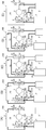
- FIG. 2 is an explanatory diagram illustrating the operation of the vehicle air conditioner.
- A shows the state during special cooling operation
- B shows the state during normal cooling operation
- C shows the state during specific heating operation
- D shows the state during normal heating operation
- E shows the state during special heating operation.
- the “special cooling operation” is an operation state in which the indoor condenser 3 is not functioned in the cooling operation.
- the “specific heating operation” is an operation state in which the dehumidifying function is particularly enhanced in the heating operation.
- the “special heating operation” is an operation state in which the outdoor heat exchanger 5 is not functioned.
- the thick line and the arrow in a figure show the flow of the refrigerant
- the proportional valve 34 is opened in the first control valve 4 and the proportional valve 37 is closed. Further, in the second control valve 6, the proportional valve 31 is opened, and the proportional valve 32 and the proportional valve 33 are closed. Further, in the third control valve 9, the proportional valve 35 is closed, and the proportional valve 36 is opened. Accordingly, the first refrigerant circulation passage is opened, and the second refrigerant circulation passage and the third refrigerant circulation passage are blocked. For this reason, the refrigerant discharged from the compressor 2 is guided to the evaporator 7 through the outdoor heat exchanger 5. At this time, the outdoor heat exchanger 5 functions as an outdoor condenser.
- the high-temperature and high-pressure gas refrigerant discharged from the compressor 2 is condensed by passing through the outdoor heat exchanger 5. Then, the refrigerant passing through the outdoor heat exchanger 5 is adiabatically expanded by the proportional valve 31 to become a cold / low pressure gas-liquid two-phase refrigerant and introduced into the evaporator 7.
- the refrigerant introduced into the inlet of the evaporator 7 evaporates in the process of passing through the evaporator 7 and cools the air in the passenger compartment.
- the refrigerant derived from the evaporator 7 is introduced into the accumulator 8 through the proportional valve 36.
- the control unit controls the opening degree of the proportional valve 31 based on the temperature on the outlet side of the outdoor heat exchanger 5 so that the degree of supercooling on the outlet side becomes appropriate.
- both the proportional valve 34 and the proportional valve 37 are opened in the first control valve 4. Further, in the second control valve 6, the proportional valve 31 and the proportional valve 33 are opened, and the proportional valve 32 is closed. Further, in the third control valve 9, the proportional valve 35 is closed, and the proportional valve 36 is opened. Thereby, the first refrigerant circulation passage and the third refrigerant circulation passage are opened, and the second refrigerant circulation passage is blocked. For this reason, the refrigerant discharged from the compressor 2 is led to the evaporator 7 through the outdoor heat exchanger 5 on the one hand, and is led to the evaporator 7 through the indoor condenser 3 on the other hand. At this time, the outdoor heat exchanger 5 functions as an outdoor condenser.
- the high-temperature and high-pressure gas refrigerant discharged from the compressor 2 is condensed by passing through the indoor condenser 3 on the one hand and the outdoor heat exchanger 5 on the other hand. Then, the refrigerant passing through the indoor condenser 3 is adiabatically expanded by the proportional valve 33, and is introduced into the evaporator 7 as a cold / low pressure gas-liquid two-phase refrigerant. Further, the refrigerant passing through the outdoor heat exchanger 5 is adiabatically expanded by the proportional valve 31 and is introduced into the evaporator 7 as a cold / low pressure gas-liquid two-phase refrigerant.
- the control unit controls the opening degree of the proportional valve 33 based on the temperature on the outlet side of the indoor condenser 3 so that the degree of supercooling on the outlet side becomes appropriate.
- the control unit also controls the opening degree of the proportional valve 31 based on the temperature on the outlet side of the outdoor heat exchanger 5 so that the degree of supercooling on the outlet side becomes appropriate.
- the high-temperature and high-pressure gas refrigerant discharged from the compressor 2 is condensed through the indoor condenser 3.
- the refrigerant derived from the indoor condenser 3 is adiabatically expanded by the proportional valve 32 to become a cold / low pressure gas-liquid two-phase refrigerant, and is evaporated when passing through the outdoor heat exchanger 5.
- the refrigerant derived from the outdoor heat exchanger 5 is introduced into the accumulator 8 through the proportional valve 35.
- the refrigerant derived from the indoor condenser 3 is adiabatically expanded by the proportional valve 33 to become a cold / low pressure gas-liquid two-phase refrigerant, and is evaporated when passing through the evaporator 7.
- the refrigerant derived from the evaporator 7 is introduced into the accumulator 8 through the proportional valve 36.
- control unit adjusts the other opening while maintaining one of the proportional valve 35 and the proportional valve 36 in the third control valve 9 in a fully opened state.
- the proportional valve 36 is fully opened to control the opening degree of the proportional valve 35.
- the proportional valve 35 is fully opened to control the opening degree of the proportional valve 36.
- the opening degree of the proportional valve 35 is increased.
- the degree of superheat is controlled so as to approach the set value (zero or a small appropriate value) by narrowing down.
- the amount of heat absorbed from the outside in the outdoor heat exchanger 5 is adjusted by the throttle amount of the proportional valve 35.
- the pressure difference ⁇ P Po ⁇ Pe between the evaporation pressure Po of the outdoor heat exchanger 5 and the pressure Pe at the outlet of the evaporator 7 is reduced by reducing the opening of the proportional valve 35 while keeping the proportional valve 36 fully open. Therefore, the ratio of evaporating the circulating refrigerant between the outdoor heat exchanger 5 and the evaporator 7 can be adjusted. That is, when the differential pressure ⁇ P increases, the evaporation amount in the outdoor heat exchanger 5 becomes relatively small (the evaporation amount in the evaporator 7 becomes relatively large).
- a control part ensures the dehumidification function at the time of specific heating operation by controlling the opening degree of the proportional valve 35 to the exit side of the outdoor heat exchanger 5 according to the degree of superheat and appropriately adjusting the differential pressure ⁇ P.
- size of the superheat degree at the exit side of the outdoor heat exchanger 5 can be specified by detecting the temperature of the inlet side of the outdoor heat exchanger 5 and the temperature of the outlet side.
- the overheating is reduced by reducing the opening degree of the proportional valve 36.
- the presence or absence of the superheat degree on the outlet side of the evaporator 7 and the magnitude thereof can be specified by detecting the temperature on the inlet side and the temperature on the outlet side of the evaporator 7.
- the proportional valve 34 of the first control valve 4 is closed and the proportional valve 37 is opened. Further, in the second control valve 6, the proportional valve 31 and the proportional valve 33 are closed, and the proportional valve 32 is opened. Further, in the third control valve 9, the proportional valve 35 is opened, and the proportional valve 36 is closed. Thereby, the first refrigerant circulation passage and the third refrigerant circulation passage are blocked, and the second refrigerant circulation passage is opened. For this reason, the refrigerant derived from the indoor condenser 3 is guided to the outdoor heat exchanger 5.
- the control unit controls the opening degree of the proportional valve 32 based on the temperature on the outlet side of the indoor condenser 3 so that the degree of supercooling on the outlet side becomes appropriate.
- the proportional valve 34 of the first control valve 4 is closed and the proportional valve 37 is opened.
- the proportional valve 31 and the proportional valve 32 are closed, and the proportional valve 33 is opened.
- the proportional valve 35 is closed, and the proportional valve 36 is opened.
- the refrigerant led out from the indoor condenser 3 is led to the evaporator 7. That is, since the refrigerant bypasses the outdoor heat exchanger 5, the outdoor heat exchanger 5 does not substantially function.
- the refrigerant introduced into the evaporator 7 evaporates in the process of passing through the evaporator 7 and dehumidifies the air in the passenger compartment.
- Such special air conditioning operation functions effectively when it is difficult to absorb heat from the outside, for example, when the vehicle is placed in an extremely cold state.
- the third control valve 9 is configured as an electric valve driven by a stepping motor, and is configured by assembling a valve main body 101 and a motor unit 102.
- the valve body 101 is configured by coaxially housing a large-diameter proportional valve 35 and a large-diameter proportional valve 36 in a bottomed cylindrical body 104, while maintaining the fully open state of one valve. It is comprised as a proportional valve which adjusts the opening degree of to a set opening degree.
- the first introduction port 110 and the second introduction port 112 are provided on one side of the body 104, and the outlet port 114 is provided on the other side.
- the first introduction port 110 communicates with the fifth passage 27, the second introduction port 112 communicates with the bypass passage 28, and the outlet port 114 communicates with the downstream passage.
- the downstream passage is connected to the inlet of the accumulator 8. That is, the body 104 has an internal passage (corresponding to a “second internal passage”) that connects the first introduction port 110 and the outlet port 114, and an internal passage that connects the second introduction port 112 and the outlet port 114 (“ Corresponding to the “first internal passage”.
- the body 104 has a hole shape in which the inner diameter of the upper part, the central part, and the lower part gradually decreases from the upper end opening part toward the bottom part.
- a port 114 is provided, and a first introduction port 110 is provided at the bottom.
- the valve hole 120 is provided in the upper-end opening part of the lower part.
- a cylindrical partition member 130 is inserted in the upper part of the body 104.
- the partition member 130 is assembled to the body 104 concentrically, and a communication hole that communicates the inside and the outside is formed on the surface facing the second introduction port 112.
- An O-ring 122 as a seal member is provided so as to be sandwiched between the lower end surface of the partition member 130 and the body 104.
- a stepped cylindrical partition member 123 is disposed at the upper end of the body 104.
- the partition member 123 partitions the inside of the valve main body 101 and the inside of the motor unit 102.
- a bearing 126 is provided at the center of the partition member 123.
- An internal thread portion is provided on the inner peripheral surface of the bearing portion 126, and the outer peripheral surface of the bearing portion 126 functions as a sliding bearing.
- a ring-shaped valve seat member 136 is fitted to the lower end portion of the partition member 123.
- the valve seat member 136 is made of an elastic body such as rubber and also functions as a seal member.
- a guide hole 138 is formed inside the partition member 123.
- the valve driver 140 has a double pipe structure including a bottomed cylindrical main body 142 and an introduction pipe 144.
- the introduction tube 144 is disposed so as to penetrate the main body 142 along the axis, and the lower end portion thereof is fixed to the center of the bottom portion of the main body 142.
- a partition portion 146 is integrally provided on the upper portion of the introduction pipe 144.
- the partition part 146 extends radially outward from the upper part of the introduction pipe 144, and the outer peripheral surface thereof is slidably supported by the guide hole 138.
- a back pressure chamber 148 is formed by a space surrounded by the partition portion 146, the partition member 123, and the motor unit 102.
- the upper end of the introduction pipe 144 is reduced in diameter, penetrates the bottom of the valve operating body 134, and the distal end thereof is caulked outward to form a locking part 150.
- a spring 152 (functioning as an “urging member”) that biases the introduction pipe 144 upward is interposed between the bottom of the valve operating body 134 and the locking portion 150. Therefore, in a normal state, the valve operating body 134 and the partition 146 are locked to each other, and the valve operating body 134 and the valve driving body 140 are operatively connected so as to be able to operate integrally (see FIG. 4). ).
- the introduction pipe 144 causes the first introduction port 110 and the back pressure chamber 148 to communicate with each other, and introduces the upstream pressure Pin1 introduced from the first introduction port 110 into the back pressure chamber 148.
- the valve driver 140 integrally includes a first valve body 154 provided at an opening end portion thereof and a second valve body 156 provided at a bottom portion thereof.
- the opening degree of the proportional valve 35 is adjusted.
- the opening degree of the proportional valve 36 is adjusted by the second valve body 156 coming into contact with and separating from the valve hole 120.
- a communication hole is provided in the side portion of the main body 142 to communicate the inside with the outlet port 114. Sealing of the outer peripheral portion of the main body 142 is realized by an O-ring 122.
- the O-ring 122 constitutes a guide portion that supports the main body 142 in a slidable manner.
- the spring 152 is set so that its load is larger than the sliding resistance between the valve driver 140 and the O-ring 122 (sliding force of the valve driver 140). Thereby, the valve opening degree of the proportional valve 35 and the proportional valve 36 can be accurately controlled without contracting the spring 152 when the valve operating body 134 and the valve driving body 140 are integrally operated.
- the effective pressure receiving diameter A of the first valve body 154 and the effective pressure receiving diameter B of the sliding portion of the valve driver 140 are set to be equal, and the effective diameter C (the first diameter of the valve hole 120) (Effective pressure receiving diameter of the two-valve body 156) and the effective diameter D of the guide hole 138 (effective pressure receiving diameter of the partition part 146) are set to be substantially equal, so that the influence of the refrigerant pressure acting on the valve driver 140 is substantially canceled. Is done. Therefore, an excessive load is not applied to the motor unit 102 due to a change in the refrigerant pressure, and the valve opening degree can be controlled stably.
- the effective diameter C of the valve hole 120 is slightly larger (predetermined minute amount) than the effective diameter D of the guide hole 138 so that the differential pressure across the second valve body 156 is slightly opened.
- the proportional valve 36 is prevented from being inadvertently closed.
- the effective diameter C of the valve hole 120 and the effective diameter D of the guide hole 138 may be set equal.
- the motor unit 102 is configured as a stepping motor including a rotor 172 and a stator 173.
- the motor unit 102 is configured to rotatably support a rotor 172 inside a bottomed cylindrical sleeve 170.
- a stator 173 that accommodates the exciting coil 171 is provided on the outer periphery of the sleeve 170.
- the lower end opening of the sleeve 170 is assembled to the body 104 and constitutes the body of the first control valve 4 together with the body 104.
- the rotor 172 includes a rotating shaft 174 formed in a cylindrical shape and a magnet 176 disposed on the outer periphery of the rotating shaft 174.
- the magnet 176 is magnetized to 24 poles.
- An internal space that extends over substantially the entire length of the motor unit 102 is formed inside the rotating shaft 174.
- a guide portion 178 extending parallel to the axis is provided at a specific location on the inner peripheral surface of the rotation shaft 174.
- the guide part 178 forms a protrusion for engaging with a rotation stopper, which will be described later, and is constituted by a single protrusion that extends parallel to the axis.
- the lower end portion of the rotating shaft 174 is slightly reduced in diameter, and four guide portions 180 extending in parallel to the axis are provided on the inner peripheral surface thereof.
- the guide portion 180 is constituted by a pair of protrusions extending in parallel to the axis, and is provided on the inner peripheral surface of the rotating shaft 174 every 90 degrees.
- the four guide portions 180 are fitted with the four leg portions 153 of the valve operating body 134 described above so that the rotor 172 and the valve operating body 134 can rotate together.
- the valve actuating member 134 is allowed to be displaced in the axial direction along the guide portion 180 although the relative displacement in the rotational direction with respect to the rotor 172 is restricted. That is, the valve actuator 134 is driven in the opening / closing direction of the valve driver 140 while rotating together with the rotor 172.
- a long shaft 182 is disposed inside the rotor 172 along the axis thereof.
- the upper end of the shaft 182 is fixed in a cantilever manner by being press-fitted into the center of the bottom of the sleeve 170, and extends into the internal space in parallel with the guide portion 178.
- the shaft 182 is disposed on the same axis as the valve operating body 134.
- the shaft 182 is provided with a spiral guide portion 184 that extends over substantially the entire length thereof.
- the guide part 184 is made of a coil-shaped member and is fitted on the outer surface of the shaft 182. An upper end portion of the guide portion 184 is folded back to form a locking portion 186.
- a helical rotation stopper 188 is rotatably engaged with the guide portion 184.
- the rotation stopper 188 includes a helical engagement portion 190 that engages with the guide portion 184 and a power transmission portion 192 that is supported by the rotation shaft 174.
- the engaging portion 190 has a shape of a one-turn coil, and a power transmission portion 192 that extends outward in the radial direction is continuously provided at a lower end portion of the engaging portion 190.
- the distal end portion of the power transmission unit 192 is engaged with the guide unit 178. That is, the power transmission part 192 is brought into contact with and locked on one protrusion of the guide part 178. For this reason, the rotation stopper 188 is restricted in relative rotation in the rotation direction by the rotation shaft 174, but is allowed to move in the axial direction while sliding on the guide portion 178.
- the rotation stopper 188 rotates integrally with the rotor 172 and is driven in the axial direction by the engagement portion 190 being guided along the guide portion 184.
- the driving range of the rotation stopper 188 in the axial direction is restricted by the engaging portions formed at both ends of the guide portion 178.
- This figure shows a state in which the rotation stopper 188 is locked at the top dead center. When the rotation stopper 188 is displaced upward and locked to the locking portion 186, the position becomes the top dead center.
- the rotor 172 has an upper end portion rotatably supported by the shaft 182 and a lower end portion rotatably supported by the bearing portion 126.
- a bottomed cylindrical end member 194 is provided so as to seal the upper end opening of the rotating shaft 174.
- a portion of the cylindrical shaft 196 provided in the center of the end member 194 is supported by a circular boss projecting from the bottom of the sleeve 170. That is, the bearing portion 126 is a bearing portion on one end side, and the sliding portion of the sleeve 170 with the cylindrical shaft 196 is a bearing portion on the other end side.
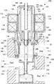
- the third control valve 9 configured as described above functions as a stepping motor actuated control valve whose valve opening can be adjusted by drive control of the motor unit 102. That is, when the proportional valve 35 is closed and the proportional valve 36 is fully opened according to the operating state of the vehicle air conditioner, the state shown in FIG. 3 is obtained.
- the third control valve 9 takes such a state during, for example, a special cooling operation, a normal cooling operation, a special heating operation, and the like.
- the rotor 172 is rotationally driven in one direction (forward rotation) from the state of FIG.
- the valve operating body 134 that rotates together with the rotor 172 is lowered by the screw mechanism and displaced so as to push down the valve driving body 140 (that is, the first valve body 154 and the second valve body 156).
- the proportional valve 35 is opened.
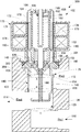
- FIG. 4 shows a neutral state in which both the proportional valve 35 and the proportional valve 36 are fully opened, but by reducing the opening degree of either one and controlling the opening degree, it is made smaller.
- the flow rate of the refrigerant flowing through the side valve can be adjusted.
- the flow rate of the refrigerant in the valve on the side where the opening is increased becomes saturated even when the opening is increased, and the valve is maintained in a fully open state which is not substantially different from the state shown in FIG. That is, the opening degree of the proportional valve 35 is adjusted by driving the first valve body 154 in a range between the fully closed state shown in FIG. 3 and the fully opened position shown in FIG.
- the rotor 172 is further rotated in the same direction from the state shown in FIG. Thereby, the valve drive body 140 is further pushed down, the second valve body 156 operates in the direction approaching the valve hole 120, and the opening degree of the proportional valve 36 is adjusted. At this time, the first valve body 154 is further driven from the state shown in FIG. 4 in the valve opening direction. However, the proportional valve 35 is in a saturated state even when the opening degree is increased, and the state shown in FIG. The fully open state is maintained substantially unchanged.
- the proportional valve 36 When closing the proportional valve 36 as in normal heating operation, the rotor 172 is further rotated in the same direction. Thereby, the proportional valve 36 can be closed as shown in FIG.
- the proportional valve 36 is configured as a so-called spool valve, and the second valve body 156 is inserted into the valve hole 120 when the valve is closed. That is, when the second valve body 156 is inserted into and removed from the valve hole 120, the proportional valve 36 is opened and closed.
- the opening degree of the proportional valve 36 is adjusted by driving the second valve body 156 in a range between the fully closed state in FIG. 5 and the fully open position in FIG. 4.
- the proportional valve 36 is a spool valve, an excessive load is not applied to the motor unit 102 even if the rotor 172 does not stop simultaneously with the closing of the proportional valve 36. Further, even if the rotor 172 does not stop simultaneously with the closing of the proportional valve 35, the spring 152 is pressed and contracted as shown in FIG. An idle mechanism that does not apply an excessive load to the motor unit 102 is provided.
- valve seat member 136 and the O-ring 122 are disposed for the proportional valve 35 to ensure the sealing performance when the valve is closed. It is not a simple configuration. This is because, as shown in FIG. 2D, the proportional valve 36 is normally closed only during heating operation. In this case, the evaporator 7 is in a dormant state as shown in FIG. This is because the proportional valve 31 and the proportional valve 33 are in the closed state, so that the refrigerant does not substantially flow into the proportional valve 36. In addition, this operation is performed when the outdoor heat exchanger 5 is at a low pressure in a low temperature state, and therefore there is little fear of backflow from the outdoor heat exchanger 5 side.
- the proportional valve 35 and the proportional valve 36 are driven by the common motor unit 102, and the other fully opened state is maintained in the control state of one opening.
- the opening degree of one proportional valve can be accurately controlled.
- FIG. 6 is a cross-sectional view illustrating a configuration of a control valve according to the second embodiment.
- the third control valve 209 is applied in place of the third control valve 9 of the first embodiment.
- the third control valve 209 is configured as an electric valve driven by a stepping motor, and is configured by assembling a valve body 201 and a motor unit 102.
- a bottomed stepped cylindrical partition member 230 is inserted across the center and lower part of the body 104.
- the partition member 230 is assembled concentrically to the body 104, and a communication hole that communicates the inside and the outside is formed on the surface facing the first introduction port 110 and the surface facing the lead-out port 114, respectively.
- An O-ring 122 is provided so as to be sandwiched between the lower end surface of the partition member 130 and the upper end surface of the partition member 230.
- a disc-shaped partition member 223 is disposed on the upper end portion of the body 104.
- the partition member 223 partitions the interior of the valve body 201 and the interior of the motor unit 102.
- a bearing 126 is provided at the center of the partition member 223.
- a valve seat member 136 is fitted on the lower surface of the partition member 223, and a guide member 238 is fixed.
- the guide member 238 is configured such that a plurality of leg portions (three in this embodiment) are erected concentrically with the body 104. Since the bottom of the guide member 238 partially overlaps the valve seat member 136, the valve seat member 136 is prevented from falling off.
- valve driving body 240 Inside the body 104, a valve driving body 240, a valve operating body 134, and a transmission rod 245 are arranged coaxially (on the same axis). A transmission rod 245 is connected to the lower end portion of the valve operating body 134.
- the valve driver 240 has a stepped cylindrical shape, and a large-diameter valve body portion 242 and a large-diameter partition portion 244 are integrally provided via a small-diameter reduced-diameter portion 246.
- the valve body portion 242 integrally includes a first valve body 154 provided at an opening end portion thereof and a second valve body 156 provided at a bottom portion.
- a communication hole for communicating the inside of the valve body portion 242 with the outlet port 114 is provided in the side portion of the valve body portion 242.
- Sealing of the outer peripheral portion of the valve body portion 242 is realized by an O-ring 122.
- the O-ring 122 constitutes a guide portion that supports the valve body portion 242 so as to be slidable.
- the partition part 244 has a disk shape, and its outer peripheral surface is slidably supported by the lower half part of the partition member 230.
- the lower half part of the partition member 230 forms a guide hole 247 that supports the partition part 244 so as to be slidable.
- the reduced diameter portion 246 is disposed so as to penetrate the valve hole 120.
- a valve seat 225 is formed by the upper end opening edge of the valve hole 120.
- the transmission rod 245 has a stepped columnar shape and penetrates the valve driver 240 in the axial direction.
- the upper end portion of the transmission rod 245 is reduced in diameter and penetrates the bottom portion of the valve operating body 134, and the distal end portion thereof is caulked outward to form a locking portion 150.
- a spring 152 is interposed between the bottom portion of the valve operating body 134 and the locking portion 150. For this reason, in a normal state, as shown in the figure, the valve operating body 134 and the transmission rod 245 are in a state of being locked and integrated with each other.
- the lower half of the transmission rod 245 is reduced in diameter and penetrates the reduced diameter portion 246 of the valve driver 240, and its tip is crimped outward in the radial direction to form a locking portion.
- a spring 249 (functioning as an “urging member”) that biases the valve driver 240 downward is interposed. .
- the transmission rod 245 and the valve driving body 240 are integrated with each other locked together.
- the springs 152 and 249 are both set so that the load is larger than the sliding resistance between the valve driver 240 and the O-ring 122 (sliding force of the valve driver 240). Thereby, the valve opening degree of the proportional valve 35 and the proportional valve 36 can be accurately controlled without contracting the springs 152 and 249 when the valve operating body 134 and the valve driving body 240 are integrally operated. Yes.
- the effective pressure receiving diameter A of the first valve body 154 and the effective pressure receiving diameter B of the sliding portion of the valve driver 240 are set to be equal, and the effective diameter C (the first diameter of the valve hole 120)
- the effective pressure receiving diameter of the two-valve body 156 and the effective diameter D of the guide hole 247 (the effective pressure receiving diameter of the partitioning portion 244) are set to be equal, so that the effect of the refrigerant pressure acting on the valve driver 240 is substantially affected. Canceled. Therefore, an excessive load is not applied to the motor unit 102 due to a change in the refrigerant pressure, and the valve opening degree can be controlled stably.
- the third control valve 209 configured as described above functions as a stepping motor actuated control valve whose valve opening can be adjusted by drive control of the motor unit 102. That is, when the proportional valve 35 is closed and the proportional valve 36 is fully opened according to the operating state of the vehicle air conditioner, the state shown in FIG. 6 is obtained.
- the rotor 172 is driven to rotate in one direction (forward rotation) from the state shown in FIG.
- the valve actuating body 134 that rotates together with the rotor 172 is lowered by the screw mechanism to displace the valve driving body 240 (that is, the first valve body 154 and the second valve body 156), and the proportional valve 35 is opened. It becomes a valve state.
- the flow rate of the refrigerant flowing through the reduced valve is adjusted by reducing the opening degree of one of the proportional valve 35 and the proportional valve 36 and controlling the opening degree. Can do. At this time, the flow rate of the refrigerant of the valve on the side where the opening degree is increased becomes saturated even when the opening degree is increased, and the fully opened state is maintained.
- FIG. 7 is a cross-sectional view illustrating a configuration of a control valve according to a modification of the first embodiment.
- the third control valve 309 of this modification does not include the O-ring 122 like the third control valve 9 shown in FIG.
- the sliding resistance of the sliding portion of the valve driver 140 in the body 304 is reduced, so that an idle mechanism (spring 152 shown in FIG. 3) is not required between the valve driver 140 and the valve actuator 134.
- the mechanism can be simplified.
- the introduction pipe 144 and the valve operating body 134 are fixed so as to sandwich the partition portion 146.
- the partition member 323 is not provided with the valve seat member 136 shown in FIG.
- the valve driver 140 is inserted and removed so that the first valve body 154 is extrapolated to the lower end of the partition member 323, and opens and closes the proportional valve 35. That is, not only the second valve body 156 but also the first valve body 154 is a spool valve. That is, the idle mechanism can be omitted by using both the first valve body 154 and the second valve body 156 integrated with the valve driver 140 as spool valve bodies constituting the spool valve. With such a simple configuration, the third control valve 309 can be realized at low cost.
- the configuration in which the first valve body 154 is extrapolated with respect to the partition member 323 is shown, but the first valve body 154 is inserted and withdrawn so as to be interpolated with respect to the partition member 323. It is good also as a structure which opens and closes 35.
Landscapes
- Engineering & Computer Science (AREA)
- General Engineering & Computer Science (AREA)
- Mechanical Engineering (AREA)
- Physics & Mathematics (AREA)
- Thermal Sciences (AREA)
- Electrically Driven Valve-Operating Means (AREA)
- Air-Conditioning For Vehicles (AREA)
- Multiple-Way Valves (AREA)
Abstract
Vanne de régulation comportant, dans un mode de réalisation : un corps commun (104) qui reçoit deux vannes proportionnelles (35 et 36) ; une unité motrice commune (102) servant à régler électriquement les ouvertures des vannes proportionnelles ; un actionneur (134) de vanne qui est entraîné axialement par l'unité motrice (102) ; un élément entraîné (140) de vanne ; et un mécanisme de changement de mode d'actionnement. L'élément entraîné (140) de vanne est une unité unique constituée : d'un premier élément (154) de vanne qui ouvre et ferme une vanne proportionnelle (35) ; et d'un deuxième élément (156) de vanne qui ouvre et ferme l'autre vanne proportionnelle (36). L'élément entraîné (140) de vanne est couplé fonctionnellement à l'actionneur (134) de vanne de façon à pouvoir se déplacer solidairement de celui-ci et est donc entraîné dans le sens de l'ouverture / de la fermeture des vannes proportionnelles. Lorsque l'ouverture d'une vanne proportionnelle (35) ou de l'autre vanne proportionnelle (36) est commandée, le mécanisme de changement de mode d'actionnement couple fonctionnellement l'actionneur (134) de vanne à l'élément entraîné (140) de vanne, et lorsque l'ouverture de l'une des vannes proportionnelles (35 ou 36) est commandée, le mécanisme de changement de mode d'actionnement peut maintenir l'autre entièrement ouverte.
Applications Claiming Priority (2)
| Application Number | Priority Date | Filing Date | Title |
|---|---|---|---|
| JP2011048551A JP5771800B2 (ja) | 2011-03-07 | 2011-03-07 | 制御弁 |
| JP2011-048551 | 2011-03-07 |
Publications (1)
| Publication Number | Publication Date |
|---|---|
| WO2012120844A1 true WO2012120844A1 (fr) | 2012-09-13 |
Family
ID=46797817
Family Applications (1)
| Application Number | Title | Priority Date | Filing Date |
|---|---|---|---|
| PCT/JP2012/001413 Ceased WO2012120844A1 (fr) | 2011-03-07 | 2012-03-01 | Vanne de régulation |
Country Status (2)
| Country | Link |
|---|---|
| JP (1) | JP5771800B2 (fr) |
| WO (1) | WO2012120844A1 (fr) |
Cited By (2)
| Publication number | Priority date | Publication date | Assignee | Title |
|---|---|---|---|---|
| US12072039B2 (en) | 2018-12-20 | 2024-08-27 | Danfoss A/S | Electric expansion valve |
| US12117215B2 (en) | 2018-12-20 | 2024-10-15 | Danfoss A/S | Valve having a motor arranged inside a tube having sections with different diameters |
Families Citing this family (3)
| Publication number | Priority date | Publication date | Assignee | Title |
|---|---|---|---|---|
| CN106337938B (zh) * | 2015-07-06 | 2019-11-05 | 杭州三花研究院有限公司 | 流量控制阀、该流量控制阀的控制方法及其控制系统 |
| WO2017022378A1 (fr) * | 2015-08-03 | 2017-02-09 | 株式会社デンソー | Vanne intégrée |
| EP4155588A1 (fr) * | 2021-09-28 | 2023-03-29 | Esbe Ab | Ensemble soupape |
Citations (4)
| Publication number | Priority date | Publication date | Assignee | Title |
|---|---|---|---|---|
| JPH02116076U (fr) * | 1989-03-06 | 1990-09-17 | ||
| JPH03282078A (ja) * | 1990-03-28 | 1991-12-12 | Ckd Corp | 電動3方弁 |
| JPH0630571U (ja) * | 1992-09-22 | 1994-04-22 | 日本ランコ株式会社 | 流量調整弁 |
| JP2001153492A (ja) * | 1999-11-30 | 2001-06-08 | Saginomiya Seisakusho Inc | 電動式切換弁および冷凍サイクル装置および冷凍・冷蔵庫用の冷凍サイクル装置 |
-
2011
- 2011-03-07 JP JP2011048551A patent/JP5771800B2/ja not_active Expired - Fee Related
-
2012
- 2012-03-01 WO PCT/JP2012/001413 patent/WO2012120844A1/fr not_active Ceased
Patent Citations (4)
| Publication number | Priority date | Publication date | Assignee | Title |
|---|---|---|---|---|
| JPH02116076U (fr) * | 1989-03-06 | 1990-09-17 | ||
| JPH03282078A (ja) * | 1990-03-28 | 1991-12-12 | Ckd Corp | 電動3方弁 |
| JPH0630571U (ja) * | 1992-09-22 | 1994-04-22 | 日本ランコ株式会社 | 流量調整弁 |
| JP2001153492A (ja) * | 1999-11-30 | 2001-06-08 | Saginomiya Seisakusho Inc | 電動式切換弁および冷凍サイクル装置および冷凍・冷蔵庫用の冷凍サイクル装置 |
Cited By (2)
| Publication number | Priority date | Publication date | Assignee | Title |
|---|---|---|---|---|
| US12072039B2 (en) | 2018-12-20 | 2024-08-27 | Danfoss A/S | Electric expansion valve |
| US12117215B2 (en) | 2018-12-20 | 2024-10-15 | Danfoss A/S | Valve having a motor arranged inside a tube having sections with different diameters |
Also Published As
| Publication number | Publication date |
|---|---|
| JP2012184885A (ja) | 2012-09-27 |
| JP5771800B2 (ja) | 2015-09-02 |
Similar Documents
| Publication | Publication Date | Title |
|---|---|---|
| JP5740596B2 (ja) | 制御弁 | |
| JP5560403B2 (ja) | ステッピングモータ駆動式の制御弁 | |
| JP5786156B2 (ja) | 車両用冷暖房装置 | |
| JP5816874B2 (ja) | 制御弁 | |
| JP5719990B2 (ja) | 車両用冷暖房装置 | |
| JP5771800B2 (ja) | 制御弁 | |
| WO2012108140A1 (fr) | Vanne de commande | |
| JP5760204B2 (ja) | 制御弁 | |
| JP5866600B2 (ja) | 車両用冷暖房装置、複合弁および制御弁 | |
| JP5613879B2 (ja) | 制御弁および車両用冷暖房装置 | |
| JP2011255689A (ja) | 車両用冷暖房装置および制御弁 | |
| WO2012090362A1 (fr) | Système de chauffage, ventilation et conditionnement d'air pour véhicule | |
| JP5760203B2 (ja) | 車両用冷暖房装置 | |
| JP5699267B2 (ja) | 制御弁 | |
| JP5629856B2 (ja) | 制御弁 | |
| JP2012225366A (ja) | 制御弁 | |
| JP5786157B2 (ja) | 制御弁 | |
| JP5786212B2 (ja) | 車両用冷暖房装置 | |
| JP5699263B2 (ja) | 車両用冷暖房装置に用いられる制御弁 |
Legal Events
| Date | Code | Title | Description |
|---|---|---|---|
| 121 | Ep: the epo has been informed by wipo that ep was designated in this application |
Ref document number: 12754750 Country of ref document: EP Kind code of ref document: A1 |
|
| NENP | Non-entry into the national phase |
Ref country code: DE |
|
| 122 | Ep: pct application non-entry in european phase |
Ref document number: 12754750 Country of ref document: EP Kind code of ref document: A1 |