WO2012120984A1 - 処理液用流量計 - Google Patents
処理液用流量計 Download PDFInfo
- Publication number
- WO2012120984A1 WO2012120984A1 PCT/JP2012/053576 JP2012053576W WO2012120984A1 WO 2012120984 A1 WO2012120984 A1 WO 2012120984A1 JP 2012053576 W JP2012053576 W JP 2012053576W WO 2012120984 A1 WO2012120984 A1 WO 2012120984A1
- Authority
- WO
- WIPO (PCT)
- Prior art keywords
- flow rate
- ultrasonic
- supply pipe
- processing liquid
- time
- Prior art date
- Legal status (The legal status is an assumption and is not a legal conclusion. Google has not performed a legal analysis and makes no representation as to the accuracy of the status listed.)
- Ceased
Links
Images

Classifications
-
- G—PHYSICS
- G01—MEASURING; TESTING
- G01F—MEASURING VOLUME, VOLUME FLOW, MASS FLOW OR LIQUID LEVEL; METERING BY VOLUME
- G01F1/00—Measuring the volume flow or mass flow of fluid or fluent solid material wherein the fluid passes through a meter in a continuous flow
- G01F1/66—Measuring the volume flow or mass flow of fluid or fluent solid material wherein the fluid passes through a meter in a continuous flow by measuring frequency, phase shift or propagation time of electromagnetic or other waves, e.g. using ultrasonic flowmeters
- G01F1/667—Arrangements of transducers for ultrasonic flowmeters; Circuits for operating ultrasonic flowmeters
-
- G—PHYSICS
- G01—MEASURING; TESTING
- G01F—MEASURING VOLUME, VOLUME FLOW, MASS FLOW OR LIQUID LEVEL; METERING BY VOLUME
- G01F1/00—Measuring the volume flow or mass flow of fluid or fluent solid material wherein the fluid passes through a meter in a continuous flow
- G01F1/66—Measuring the volume flow or mass flow of fluid or fluent solid material wherein the fluid passes through a meter in a continuous flow by measuring frequency, phase shift or propagation time of electromagnetic or other waves, e.g. using ultrasonic flowmeters
-
- G—PHYSICS
- G01—MEASURING; TESTING
- G01F—MEASURING VOLUME, VOLUME FLOW, MASS FLOW OR LIQUID LEVEL; METERING BY VOLUME
- G01F1/00—Measuring the volume flow or mass flow of fluid or fluent solid material wherein the fluid passes through a meter in a continuous flow
- G01F1/74—Devices for measuring flow of a fluid or flow of a fluent solid material in suspension in another fluid
-
- G—PHYSICS
- G01—MEASURING; TESTING
- G01N—INVESTIGATING OR ANALYSING MATERIALS BY DETERMINING THEIR CHEMICAL OR PHYSICAL PROPERTIES
- G01N29/00—Investigating or analysing materials by the use of ultrasonic, sonic or infrasonic waves; Visualisation of the interior of objects by transmitting ultrasonic or sonic waves through the object
- G01N29/02—Analysing fluids
Definitions
- the present invention relates to a flowmeter for a processing solution that is suitably used for a processing solution such as a resist solution.
- the photoresist coating apparatus imparts photosensitivity to the wafer by coating the photoresist extremely thinly and uniformly on the wafer.
- the photoresist coating apparatus when uniformly applying a photoresist on a wafer, if bubbles are included in the resist solution, there is a problem that coating unevenness occurs and the coating cannot be performed uniformly.
- a bubble detection unit is provided in a supply pipe for supplying a resist solution to a photoresist apparatus so that the presence or absence of bubbles in the resist solution can be automatically detected.
- a flowmeter for measuring the flow rate of the resist solution a flowmeter for measuring the flow rate of the resist solution, and the like are provided on the supply pipe in order to uniformly apply the photoresist.
- the present invention has been made to solve the above problems all at once, and in order to simplify the configuration on the supply pipe by providing various functions to the flowmeter for treatment liquid,
- the main intended problem is to provide a treatment liquid flowmeter having a function of judging contamination, a function of suitably measuring flow rates of various treatment liquids, or a function of detecting a backflow of treatment liquids. .
- the flowmeter for processing liquid measures the flow velocity of the processing liquid flowing through the supply pipe, and includes a pair of ultrasonic transducers arranged at a certain distance in the flow direction of the supply pipe.
- a first arrival time which is a time for the ultrasonic wave emitted from one ultrasonic transducer to reach the other ultrasonic transducer, and an ultrasonic wave emitted from the other ultrasonic transducer is the first ultrasonic transducer
- the flow rate calculation unit that calculates the flow rate of the treatment liquid, and the treatment liquid based on the calculated time variation of the flow rate of the treatment liquid.
- a bubble mixing determination unit that determines whether or not bubbles are mixed, and a flow rate calculation unit that calculates a flow rate based on the flow velocity calculated by the flow velocity calculation unit and the cross-sectional area of the supply pipe. It is characterized by being.
- a flow meter using an ultrasonic transducer can be provided with a bubble mixing judgment function for judging bubble mixing in the processing liquid. Therefore, it is not necessary to provide a bubble detector separately from the flow meter on the supply pipe, and the configuration on the supply pipe can be simplified.
- a minute flow rate of, for example, 15 [ml / min] or less can be measured.
- the bubble mixing determination unit determines that bubbles are mixed in the processing liquid when the time change amount exceeds a predetermined threshold. It is desirable to do.
- the processing liquid flowmeter measures a flow rate of the processing liquid flowing through the supply pipe, and includes a pair of ultrasonic transducers arranged at a predetermined distance in the flow direction of the supply pipe.
- a first arrival time which is a time for the ultrasonic wave emitted from one ultrasonic transducer to reach the other ultrasonic transducer, and an ultrasonic wave emitted from the other ultrasonic transducer is the one ultrasonic wave
- a second flow time that is a time to reach the vibrator and a flow rate calculation unit that calculates a flow rate of the processing liquid based on the type of the processing liquid are provided. In such a case, the flow rate can be automatically calculated in consideration of the type of processing liquid.
- the flow rate calculation unit includes the first arrival time and the second arrival time as parameters. It is desirable to calculate the flow rate of the processing solution by obtaining the flow rate of the predetermined standard solution from the calculation formula and multiplying the standard solution flow rate by a coefficient predetermined for each processing solution.
- the flowmeter for processing liquid measures the flow velocity of the processing liquid flowing through the supply pipe, and includes a pair of ultrasonic transducers arranged at a certain distance in the flow direction of the supply pipe.
- a first arrival time which is a time for the ultrasonic wave emitted from one ultrasonic transducer to reach the other ultrasonic transducer, and an ultrasonic wave emitted from the other ultrasonic transducer is the one ultrasonic wave
- a flow rate calculation unit that calculates a flow rate of the treatment liquid based on a second arrival time that is a time to reach the vibrator, and the flow rate calculation unit performs processing when a negative value of flow rate is calculated. It is determined that the liquid is flowing in the opposite direction. If it is such, the flowmeter for process liquids which can detect suitably that the process liquid is flowing in the reverse direction when the flow velocity is a negative value can be provided.
- a function capable of suitably measuring the flow rate of various processing liquids, or a function of detecting a backflow of the processing liquid for a processing liquid having a function of determining the mixing of bubbles into the processing liquid, a function capable of suitably measuring the flow rate of various processing liquids, or a function of detecting a backflow of the processing liquid.
- a flow meter can be provided for a processing liquid having a function of determining the mixing of bubbles into the processing liquid.
- the schematic diagram of the flowmeter for process liquids of this embodiment The schematic diagram which shows the 2nd arrival time of 1st arrival time.
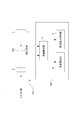
- the flowmeter 100 for processing liquid measures the flow rate and flow rate of a resist solution flowing through a supply pipe 200 made of, for example, a PFA tube connected to a photoresist coating apparatus of a semiconductor manufacturing apparatus (not shown).
- a supply pipe 200 made of, for example, a PFA tube connected to a photoresist coating apparatus of a semiconductor manufacturing apparatus (not shown).
- the supply pipe 200 is composed of a PFA tube, there is no pressure loss such as a restriction, so that bubbles are hardly generated.
- this includes a pair of ultrasonic transducers 2 and 3 arranged at a certain distance in the flow direction of the supply pipe, and a pair of ultrasonic transducers 2 and 3.
- the flow rate calculation unit 4 that receives the obtained detection signal and calculates the flow rate of the resist solution, and determines whether or not bubbles are mixed in the resist solution based on the calculated temporal change amount of the flow rate of the resist solution.
- a bubble mixing determination unit 5 and a flow rate calculation unit 6 that calculates a flow rate based on the flow rate calculated by the flow rate calculation unit 4 and the cross-sectional area of the supply pipe 200 are provided.
- the flow velocity calculation unit 4, the bubble mixing determination unit 5 and the flow rate calculation unit 6 include a CPU, a memory, an AD converter, a DA converter, an input / output interface, and the like, and the CPU and peripheral devices cooperate in accordance with a predetermined program stored in the memory. It is configured by a general-purpose or dedicated so-called computer 300 that operates and operates. In addition, these 4 to 6 may be configured using discrete circuits.
- One ultrasonic transducer 2 provided on the upstream side is driven by a drive circuit (not shown) and transmits ultrasonic waves toward the other ultrasonic transducer 3.
- the one ultrasonic transducer 2 receives ultrasonic waves transmitted from the other ultrasonic transducer 3.
- the signal received by one ultrasonic transducer 2 is amplified with a predetermined gain by an amplification circuit (not shown) and transmitted to the flow velocity calculation unit 4.
- the other ultrasonic transducer 3 provided on the downstream side is driven by a drive circuit (not shown) similarly to the one ultrasonic transducer 2 and transmits ultrasonic waves toward the one ultrasonic transducer 2. Is.
- the other ultrasonic transducer 3 receives the ultrasonic wave transmitted from the one ultrasonic transducer 2.
- the signal received by the other ultrasonic transducer 3 is amplified with a predetermined gain by an amplification circuit (not shown) and transmitted to the flow velocity calculation unit 4.
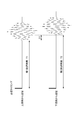
- the flow velocity calculation unit 4 receives the detection signals from the pair of ultrasonic transducers 2 and 3 and, as shown in FIG. 2, the ultrasonic wave emitted from one ultrasonic transducer 2 is the other ultrasonic vibration.
- a first arrival time T1 that is a time to reach the child 3 and a second arrival time T2 that is a time for the ultrasonic wave emitted from the other ultrasonic transducer 3 to reach the one ultrasonic transducer 2 Is calculated.
- the flow velocity calculation unit 4 calculates the flow velocity of the resist solution based on the first arrival time T1 and the second arrival time T2.
- the flow velocity calculation unit 4 calculates the flow velocity V (ml / min) by the following equation.
- L is the distance between the ultrasonic transducers 2 and 3.
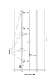
- the bubble mixing determination unit 5 acquires the flow velocity data calculated from the flow velocity calculation unit 4, and determines whether or not bubbles are mixed in the resist solution based on the amount of change in the flow rate over time. Specifically, as shown in FIG. 3, the bubble mixing determination unit 5 determines that bubbles are mixed in the resist solution when the temporal change amount of the instantaneous value of the flow velocity exceeds a predetermined threshold value.
- S is a flow path cross-sectional area of the supply pipe 200
- k is a correction coefficient (a correction value such as a flow path diameter of the supply pipe and an inter-vibrator distance).
- the flow meter using the ultrasonic vibrators 2 and 3 is provided with a bubble mixing determination function for determining bubble mixing in the resist solution. be able to. Therefore, it is not necessary to provide a bubble detection unit separately from the flow meter 100 on the supply pipe 200, the configuration on the supply pipe 200 can be simplified, and the size of the apparatus is increased without complicating maintenance work. Without being able to judge the inclusion of bubbles.
- the flow velocity is calculated using the ultrasonic transducers 2 and 3, a minute flow rate of, for example, 15 [ml / min] or less can be measured.
- the flow velocity calculation unit 4 of the above embodiment may calculate the flow velocity of the resist solution based on the first arrival time T1, the second arrival time T2, and the type of the resist solution.
- the processing liquid flowmeter 100 has a coefficient data storage unit D1 for storing coefficient data indicating coefficients determined from the physical property values of the resist solutions and the like with respect to the standard solution.
- the flow velocity calculation unit 4 obtains a flow velocity in a predetermined standard solution from a flow velocity calculation formula including the first arrival time T1 and the second arrival time T2 as parameters, and further calculates coefficient data for the standard solution flow velocity.
- the flow rate of the resist solution is calculated by multiplying a predetermined coefficient for each resist solution.
- the flow velocity calculation unit of the above embodiment calculates a negative flow velocity, it can be configured to determine that the resist solution is flowing in the reverse direction.
- the flow rate of the resist solution is measured as the processing solution, but other than that, the flow rate of the etching solution or the like may be measured.
- the function for judging the mixing of bubbles into the processing liquid, and the flow rate of various processing liquids are preferably measured. It is possible to provide a processing liquid flowmeter having a function capable of detecting or detecting a backflow of the processing liquid.
Landscapes
- Physics & Mathematics (AREA)
- General Physics & Mathematics (AREA)
- Fluid Mechanics (AREA)
- Electromagnetism (AREA)
- Analytical Chemistry (AREA)
- Health & Medical Sciences (AREA)
- Life Sciences & Earth Sciences (AREA)
- Chemical & Material Sciences (AREA)
- Acoustics & Sound (AREA)
- Biochemistry (AREA)
- General Health & Medical Sciences (AREA)
- Immunology (AREA)
- Pathology (AREA)
- Measuring Volume Flow (AREA)
- Investigating Or Analyzing Materials By The Use Of Ultrasonic Waves (AREA)
- Exposure Of Semiconductors, Excluding Electron Or Ion Beam Exposure (AREA)
Abstract
Description
200・・・供給配管
2 ・・・一方の超音波振動子
3 ・・・他方の超音波振動子
T1 ・・・第1到達時間
T2 ・・・第2到達時間
4 ・・・流速算出部
5 ・・・気泡混入判断部
6 ・・・流量算出部
D1 ・・・係数データ格納部

このように構成した本実施形態に係るレジスト液用流量計100によれば、超音波振動子2、3を用いた流量計において、レジスト液中の気泡混入を判断する気泡混入判断機能を持たせることができる。したがって供給配管200上に流量計100と別に気泡検出部を設ける必要が無く、供給配管200上の構成を簡単化することができ、メンテナンス作業を煩雑にすることなく、装置の大型化を招くことなく、気泡混入を判断できるようになる。また超音波振動子2、3を用いて流速を算出していることから、例えば15[ml/min]以下の微小な流量を計測することができる。
なお、本発明は前記実施形態に限られるものではない。
Claims (5)
- 供給配管を流れる処理液の流速を測定するものであって、
前記供給配管の流れ方向に一定距離離間して配置された一対の超音波振動子と、
一方の超音波振動子から発された超音波が他方の超音波振動子に到達する時間である第1到達時間、及び、前記他方の超音波振動子から発された超音波が前記一方の超音波振動子に到達する時間である第2到達時間に基づいて、前記処理液の流速を算出する流速算出部と、
算出された前記処理液の流速の時間変化量に基づいて、該処理液に気泡が混入しているか否かを判断する気泡混入判断部と、
前記流速算出部で算出された流速と前記供給配管の断面積に基づいて、流量を算出する流量算出部とを具備していることを特徴とする処理液用流量計。 - 前記気泡混入判断部は、前記時間変化量が所定の閾値を超えた場合に、該処理液に気泡が混入していると判断する請求項1記載の処理液用流量計。
- 供給配管を流れる処理液の流速を測定するものであって、
前記供給配管の流れ方向に一定距離離間して配置された一対の超音波振動子と、
一方の超音波振動子から発された超音波が他方の超音波振動子に到達する時間である第1到達時間、前記他方の超音波振動子から発された超音波が前記一方の超音波振動子に到達する時間である第2到達時間、及び、前記処理液の種類に基づいて、前記処理液の流速を算出する流速算出部とを具備していることを特徴とする処理液用流量計。 - 前記流速算出部は、前記第1到達時間及び第2到達時間をパラメータとして含んだ流速算出式から所定の標準液での流速を求め、さらにその標準液流速に対して、処理液毎に予め定められた係数を乗じて当該処理液の流速を算出する請求項3記載の処理液用流量計。
- 供給配管を流れる処理液の流速を測定するものであって、
前記供給配管の流れ方向に一定距離離間して配置された一対の超音波振動子と、
一方の超音波振動子から発された超音波が他方の超音波振動子に到達する時間である第1到達時間、前記他方の超音波振動子から発された超音波が前記一方の超音波振動子に到達する時間である第2到達時間に基づいて、前記処理液の流速を算出する流速算出部とを具備し、
前記流速算出部は、負の値の流速を算出した場合に、処理液が逆方向に流れていると判断するものであることを特徴とする処理液用流量計。
Priority Applications (3)
| Application Number | Priority Date | Filing Date | Title |
|---|---|---|---|
| CN201280011309XA CN103403503A (zh) | 2011-03-09 | 2012-02-15 | 处理液用流量计 |
| KR1020137026299A KR20140019792A (ko) | 2011-03-09 | 2012-02-15 | 처리액용 유량계 |
| US14/003,774 US20130345996A1 (en) | 2011-03-09 | 2012-02-15 | Process liquid flowmeter |
Applications Claiming Priority (2)
| Application Number | Priority Date | Filing Date | Title |
|---|---|---|---|
| JP2011052228A JP2012189401A (ja) | 2011-03-09 | 2011-03-09 | 処理液用流量計 |
| JP2011-052228 | 2011-03-09 |
Publications (1)
| Publication Number | Publication Date |
|---|---|
| WO2012120984A1 true WO2012120984A1 (ja) | 2012-09-13 |
Family
ID=46797953
Family Applications (1)
| Application Number | Title | Priority Date | Filing Date |
|---|---|---|---|
| PCT/JP2012/053576 Ceased WO2012120984A1 (ja) | 2011-03-09 | 2012-02-15 | 処理液用流量計 |
Country Status (6)
| Country | Link |
|---|---|
| US (1) | US20130345996A1 (ja) |
| JP (1) | JP2012189401A (ja) |
| KR (1) | KR20140019792A (ja) |
| CN (1) | CN103403503A (ja) |
| TW (1) | TW201245672A (ja) |
| WO (1) | WO2012120984A1 (ja) |
Cited By (1)
| Publication number | Priority date | Publication date | Assignee | Title |
|---|---|---|---|---|
| EP2717026A3 (en) * | 2012-10-04 | 2016-03-16 | Sonotec Ultraschallsensorik Halle GmbH | Method of and apparatus for determining a flow rate of a fluid and detecting gas bubbles or particles in the fluid |
Families Citing this family (9)
| Publication number | Priority date | Publication date | Assignee | Title |
|---|---|---|---|---|
| US9170033B2 (en) | 2010-01-20 | 2015-10-27 | Brightsource Industries (Israel) Ltd. | Method and apparatus for operating a solar energy system to account for cloud shading |
| US9249785B2 (en) * | 2012-01-31 | 2016-02-02 | Brightsource Industries (Isreal) Ltd. | Method and system for operating a solar steam system during reduced-insolation events |
| EP2913641B1 (en) | 2014-02-28 | 2019-07-31 | Yokogawa Electric Corporation | Multiphase flowmeter |
| US9996089B2 (en) | 2015-09-21 | 2018-06-12 | Blue-White Industries, Ltd. | Flow sensor devices and systems |
| US11150118B2 (en) * | 2016-09-23 | 2021-10-19 | Blue-White Industries, Ltd. | Flow sensor devices and systems |
| US11730895B2 (en) * | 2016-09-29 | 2023-08-22 | Koninklijke Philips N.V. | Medical device with a thermal mass flow sensor for bubble detection |
| US11639863B2 (en) | 2019-06-07 | 2023-05-02 | Blue-White Industries, Ltd. | Flow sensor devices and systems |
| FR3109631B1 (fr) * | 2020-04-22 | 2022-04-15 | Sagemcom Energy & Telecom Sas | Procédé de mesure ultrasonique avec prise en compte de la quantité de bulles gazeuses |
| CN119186937B (zh) * | 2024-11-22 | 2025-03-07 | 深圳市曼希尔科技有限公司 | 电池极片制造设备、电池极片生产控制系统及方法 |
Citations (2)
| Publication number | Priority date | Publication date | Assignee | Title |
|---|---|---|---|---|
| JP2004226391A (ja) * | 2002-11-25 | 2004-08-12 | Fuji Electric Retail Systems Co Ltd | 超音波流量計 |
| JP2006337313A (ja) * | 2005-06-06 | 2006-12-14 | Saginomiya Seisakusho Inc | 超音波流量計 |
Family Cites Families (5)
| Publication number | Priority date | Publication date | Assignee | Title |
|---|---|---|---|---|
| JP2002116073A (ja) * | 2000-10-10 | 2002-04-19 | Osaka Gas Co Ltd | 流量測定方法 |
| WO2007022052A1 (en) * | 2005-08-12 | 2007-02-22 | Celerity, Inc. | Flow measurement and control with bubble detection |
| JP2008096297A (ja) * | 2006-10-12 | 2008-04-24 | Dainippon Screen Mfg Co Ltd | 基板処理装置および処理液流量計測方法 |
| JP5608884B2 (ja) * | 2009-05-09 | 2014-10-22 | 本多電子株式会社 | 超音波流量計及び流体供給システム |
| CN101614569B (zh) * | 2009-07-20 | 2011-09-21 | 北京工业大学 | 基于超声导波技术的管道液体流量测量方法 |
-
2011
- 2011-03-09 JP JP2011052228A patent/JP2012189401A/ja active Pending
-
2012
- 2012-02-15 WO PCT/JP2012/053576 patent/WO2012120984A1/ja not_active Ceased
- 2012-02-15 CN CN201280011309XA patent/CN103403503A/zh active Pending
- 2012-02-15 KR KR1020137026299A patent/KR20140019792A/ko not_active Withdrawn
- 2012-02-15 US US14/003,774 patent/US20130345996A1/en not_active Abandoned
- 2012-03-08 TW TW101107796A patent/TW201245672A/zh unknown
Patent Citations (2)
| Publication number | Priority date | Publication date | Assignee | Title |
|---|---|---|---|---|
| JP2004226391A (ja) * | 2002-11-25 | 2004-08-12 | Fuji Electric Retail Systems Co Ltd | 超音波流量計 |
| JP2006337313A (ja) * | 2005-06-06 | 2006-12-14 | Saginomiya Seisakusho Inc | 超音波流量計 |
Cited By (1)
| Publication number | Priority date | Publication date | Assignee | Title |
|---|---|---|---|---|
| EP2717026A3 (en) * | 2012-10-04 | 2016-03-16 | Sonotec Ultraschallsensorik Halle GmbH | Method of and apparatus for determining a flow rate of a fluid and detecting gas bubbles or particles in the fluid |
Also Published As
| Publication number | Publication date |
|---|---|
| CN103403503A (zh) | 2013-11-20 |
| US20130345996A1 (en) | 2013-12-26 |
| TW201245672A (en) | 2012-11-16 |
| JP2012189401A (ja) | 2012-10-04 |
| KR20140019792A (ko) | 2014-02-17 |
Similar Documents
| Publication | Publication Date | Title |
|---|---|---|
| WO2012120984A1 (ja) | 処理液用流量計 | |
| WO2017004887A1 (zh) | 一种时差式超声波流量测量方法及装置 | |
| JP6309405B2 (ja) | 超音波流量計及び流量の計測方法 | |
| WO2014068952A1 (ja) | 流量計測装置およびその流量算出方法 | |
| CN105067056A (zh) | 超声波流量计以及超声波吸收体的异常判定方法 | |
| WO2016091208A1 (zh) | 测量方法及系统 | |
| US20160290845A1 (en) | Ultrasonic flowmeter, flow velocity measurement method, and flow velocity measurement program | |
| JP2011145289A (ja) | 流量計測装置 | |
| CN106643937A (zh) | 一种基于超声波流量计的流量测量方法及装置 | |
| JP5608884B2 (ja) | 超音波流量計及び流体供給システム | |
| JP2008304281A (ja) | 超音波流量測定方法、超音波流量計、及び超音波流量測定プログラム | |
| US10801876B1 (en) | Self-checking ultrasonic fluid flow measurement system | |
| JP5282955B2 (ja) | 超音波流量計の補正方法、及び超音波流量計 | |
| JP2010261872A (ja) | 超音波流量計 | |
| JP4738897B2 (ja) | 超音波流量計 | |
| JP5641491B2 (ja) | 超音波流量計 | |
| WO2006080182A1 (ja) | 超音波流量計、2方式併用型超音波流量計 | |
| CN100380101C (zh) | 多普勒型超声波流量计 | |
| WO2019047634A1 (zh) | 一种直线距离上平均流体流速测量系统 | |
| KR101764870B1 (ko) | 초음파 유량계의 신호처리시스템 | |
| JP2013250254A (ja) | 超音波式スパイロメータの多重反射防止整流管 | |
| JP7125340B2 (ja) | 超音波流量計、流量演算装置、および非満水状態判定方法 | |
| TWI772111B (zh) | 傳播時間測定裝置 | |
| JP6064160B2 (ja) | 流量計測装置 | |
| JP2001194197A (ja) | 超音波流量計 |
Legal Events
| Date | Code | Title | Description |
|---|---|---|---|
| 121 | Ep: the epo has been informed by wipo that ep was designated in this application |
Ref document number: 12755159 Country of ref document: EP Kind code of ref document: A1 |
|
| WWE | Wipo information: entry into national phase |
Ref document number: 14003774 Country of ref document: US |
|
| NENP | Non-entry into the national phase |
Ref country code: DE |
|
| ENP | Entry into the national phase |
Ref document number: 20137026299 Country of ref document: KR Kind code of ref document: A |
|
| 122 | Ep: pct application non-entry in european phase |
Ref document number: 12755159 Country of ref document: EP Kind code of ref document: A1 |