WO2012121114A1 - Système de réseau, dispositif réseau et procédé de commande de chemin - Google Patents
Système de réseau, dispositif réseau et procédé de commande de chemin Download PDFInfo
- Publication number
- WO2012121114A1 WO2012121114A1 PCT/JP2012/055272 JP2012055272W WO2012121114A1 WO 2012121114 A1 WO2012121114 A1 WO 2012121114A1 JP 2012055272 W JP2012055272 W JP 2012055272W WO 2012121114 A1 WO2012121114 A1 WO 2012121114A1
- Authority
- WO
- WIPO (PCT)
- Prior art keywords
- route
- packet
- flow entry
- flow
- switch
- Prior art date
- Legal status (The legal status is an assumption and is not a legal conclusion. Google has not performed a legal analysis and makes no representation as to the accuracy of the status listed.)
- Ceased
Links
Images






Classifications
-
- H—ELECTRICITY
- H04—ELECTRIC COMMUNICATION TECHNIQUE
- H04L—TRANSMISSION OF DIGITAL INFORMATION, e.g. TELEGRAPHIC COMMUNICATION
- H04L45/00—Routing or path finding of packets in data switching networks
- H04L45/38—Flow based routing
Definitions
- the present invention relates to a network system, and more particularly to a controller that performs network communication path control.
- CU control plane / U: user plane
- control plane control plane
- OpenFlow open flow
- a controller such as OFC (OpenFlow Controller) controls the behavior of a switch by operating a flow table (Flow table) in the switch such as OFS (OpenFlow Switch).
- OFC OpenFlow Controller
- Flow table flow table
- OFS OpenFlow Switch
- the switches in the OpenFlow network system are edge switches and core switches that form an OpenFlow network and are under the control of the controller.
- a series of packet flows from reception of a packet at the input side edge switch to transmission at the output side edge switch in the OpenFlow network is called a flow.
- the packet may be read as a frame.
- the difference between a packet and a frame is only the difference in the data unit (PDU: Protocol Data Unit) handled by the protocol.
- the packet is a PDU of “TCP / IP” (Transmission Control Protocol / Internet Protocol).
- the frame is a PDU of “Ethernet” (registered trademark).
- the flow table is a table in which a flow entry (Flow entry) that defines an action (action) to be performed on a packet that meets a predetermined match condition (rule) is registered.
- Flow entry a flow entry that defines an action (action) to be performed on a packet that meets a predetermined match condition (rule) is registered.
- the rule of the flow entry is one of a destination address (Destination Address), a source address (Source Address), a destination port (Destination Port), a source port (Source Port) included in the header area of each protocol layer of the packet, or Defined and distinguishable by various combinations using all.
- the above address includes a MAC address (Media Access Control Address) and an IP address (Internet Protocol Address).
- information on the ingress port (Ingress Port) can also be used as a rule for the flow entry.
- a part (or all) of the header area value of the packet indicating the flow can be set by a regular expression, a wild card “*”, or the like.
- the action of the flow entry indicates operations such as “output to a specific port”, “discard”, and “rewrite header”. For example, if the identification information (output port number, etc.) of the output port is indicated in the action of the flow entry, the switch outputs a packet to the corresponding port, and if the identification information of the output port is not indicated , Discard the packet. Alternatively, if the header information is indicated in the action of the flow entry, the switch rewrites the header of the packet based on the header information.
- the switch in the OpenFlow network system executes a flow entry action on a packet group (packet sequence) that conforms to the flow entry rules.
- Japanese Patent Application Laid-Open No. 2006-020054 discloses a network connection device, a route information distribution program, and a route information distribution method.
- a route information update notification message is generated based on a prefix assigned to a child router, information on an assignment destination child router, and an assignment management table. This message conveys the possibility of updating (adding or deleting) route information.
- a route information update notification is transmitted to a router to which a prefix has already been assigned.
- a network repeater is disclosed in Patent Document 2 (Japanese Patent Laid-Open No. 2007-096912).
- a route information change packet is received from a network processor (NP) and the event is interpreted. The interpretation of the event is performed based on the header information of the route information change packet.
- a route information addition process is executed.
- a route information change process is executed.
- a route information deletion process is executed.
- the processing is completed for all the route information change packets from the network processor (NP), a timer for starting the request transmission processing to the network processor (NP) is set.
- a method can be considered in which a network device adds information to a packet, and a network device on the route reads the information to forward the packet to the correct route.
- the present invention proposes a technique in which the network device does not change the packet itself while ensuring that the packet is transferred from the transmission source to the transmission destination.
- the network system includes a plurality of network devices, a plurality of controllers that set a flow entry in which rules and operations for uniformly controlling packets as flows are defined in a flow table of network devices on a route, including.
- the network device on the route adopts the route set by the controller that has completed the setting of the flow entry of all the network devices on the route earliest among the plurality of controllers, and sets the route set by the other controller.
- the packet is not adopted and the packet is transferred according to the flow entry of the adopted route.
- a network device includes a device that sets a flow entry in a flow table in which rules and operations for uniformly controlling a packet as a flow are defined in a flow table based on control from each of a plurality of controllers, Adopt the route set by the controller that completed the setting of the flow entry of all the network devices on the route the earliest among the controllers of the other, and reject the route set by the other controller, and the flow of the adopted route And a device for transferring a packet according to the entry.
- the route control method is a route control method implemented by a network device, and rules and operations for uniformly controlling packets as a flow are defined based on control from each of a plurality of controllers.
- Set the flow entry in the flow table adopt the route set by the controller that completed the flow entry setting of all the network devices on the route earliest among the multiple controllers, and set other controllers Including transferring the packet in accordance with the flow entry of the adopted route.
- the program according to the present invention includes a step of setting, in the flow table, a flow entry in which rules and operations for uniformly controlling a packet as a flow are defined based on control from each of a plurality of controllers. Adopts the route set by the controller that has completed the setting of the flow entry of all the network devices on the route earliest among the controllers, disallows the route set by the other controller, and the flow entry of the adopted route.
- the program for causing the network device to execute the step of transferring packets according to the above.
- the program according to the present invention is a program for causing a network device to execute the processing in the above path control method.
- the program according to the present invention can be stored in a storage device or a storage medium.
- the present invention is directed to a CU separation type network system.
- an OpenFlow network system which is one of CU separation type network systems, will be described as an example. However, actually, it is not limited to the open flow network system.
- a computer such as a PC (personal computer), an appliance, a thin client server, a workstation, a mainframe, and a supercomputer is assumed.
- a network switch (network switch) is assumed.
- a router a proxy, a gateway, a firewall, a load balancer, a bandwidth control device, a security monitoring control device, a base station, an access point, or a computer having a plurality of communication ports Conceivable.
- the above computer is assumed.
- mobile phones, car navigation systems (car navigation systems), portable game consoles, home game consoles, portable music players, handy terminals, gadgets (electronic devices), interactive TVs, digital tuners, digital recorders, information appliances (Information home application), OA (Office Automation) equipment, etc. can be considered.
- VM Virtual Machine
- a processor that drives based on this and executes predetermined processing
- a memory that stores the program and various data
- an interface used for communication with the network
- processors include a CPU (Central Processing Unit), a network processor (NP: Network Processor), a microprocessor (microprocessor), a microcontroller (microcontroller), or a semiconductor integrated circuit (LSI: Large Scale) having a dedicated function. Integration) or the like.
- CPU Central Processing Unit
- NP Network Processor
- microprocessor microprocessor
- microcontroller microcontroller
- LSI semiconductor integrated circuit
- semiconductor storage devices such as RAM (Random Access Memory), ROM (Read Only Memory), EEPROM (Electrically Erasable and Programmable Read Only Memory), and HDD Memory (SDHidK)
- RAM Random Access Memory
- ROM Read Only Memory
- EEPROM Electrical Erasable and Programmable Read Only Memory
- HDD Memory HDD Memory
- An auxiliary storage device such as State Drive
- a removable disk such as a DVD (Digital Versatile Disk)
- a storage medium such as an SD memory card (Secure Digital memory card), or the like is conceivable.
- a register may also be used.
- processor and the memory may be integrated.
- a single chip such as a microcomputer has been developed. Therefore, a case where a one-chip microcomputer mounted on the above-described computer or the like includes a processor and a memory can be considered.
- Examples of the above interfaces include semiconductor integrated circuits such as boards (motherboards and I / O boards) and chips that support network communication, network adapters such as NIC (Network Interface Card), and communication devices such as expansion cards and antennas.
- NIC Network Interface Card
- a communication port such as a connection port (connector) is conceivable.
- networks include the Internet, LAN (Local Area Network), wireless LAN (Wireless LAN), WAN (Wide Area Network), backbone (Backbone), cable TV (CATV) line, fixed telephone network, mobile phone network, WiMAX (IEEE 802.16a), 3G (3rd Generation), dedicated line (lease line), IrDA (Infrared Data Association), Bluetooth (registered trademark), serial communication line, data bus, and the like are conceivable.
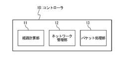
- route calculation unit 11, the network management unit 12, and the packet processing unit 13 may be modules or components.
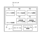
- the flow table 21 manages flow entries that are route information.
- the flow table 21 can be stored in a storage device or a storage medium.
- the flow table management unit 22 can also check the contents of the flow entry in the flow table 21.
- the packet processing unit 23 includes a packet reception unit 231, a packet transfer unit 232, a packet discard unit 233, a route deletion packet generation unit 234, and a route deletion packet analysis unit 235.
- the packet transfer unit 232 is provided for each output port, and outputs the received packet from the output port.
- the packet discard unit 233 discards the received packet. Note that the packet discard unit 233 can discard not only the normal packet but also a route deletion packet described later.
- the route deletion packet generation unit 234 generates a route deletion packet for deleting the unaccepted route.
- the route deletion packet analysis unit 235 analyzes the received route deletion packet. As a packet analysis, the route deletion packet analysis unit 235 refers to the header information of the route deletion packet, and checks whether there is a flow entry of a rejected route that matches the header information of the route deletion packet in the flow table 21. If there is a matching flow entry, and if the content of the flow entry is to be transferred to the next node on the route, the packet receiving unit 231 passes the route deletion packet to the packet transfer unit 232, and the next on the route. Transfer to the node of the stage. If the content of the flow entry is to discard the route deletion packet, the packet reception unit 231 passes the route deletion packet to the packet discard unit 233 and discards the route deletion packet.
- the route deletion packet analysis unit 235 temporarily holds the route deletion packet, passes the route deletion packet to the packet discard unit 233 after a predetermined time elapses, and receives the route deletion packet. Discard.
- the route deletion packet analysis unit 235 may be integrated with the packet reception unit 231.
- the flow table management unit 22 and the packet processing unit 23 are modules. Alternatively, it may be a component.
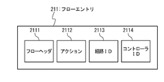
- the flow table 21 holds a flow entry 211. That is, the flow table 21 is a set of flow entries 211. The flow entry 211 is route information corresponding to each flow.
- the flow entry 211 includes a flow header 2111, an action 2112, a route ID 2113, and a controller ID 2114.
- the flow header 2111 is an area (field) for describing basic information of a flow such as a transmission source IP address and a transmission destination IP address. That is, the flow header 2111 is an area for describing the rule of the flow entry 211.
- Action 2112 is an area for describing a flow processing method. That is, the action 2112 is an area for describing the action of the flow entry 211.
- Route ID 2113 is an area for describing a unique value (route identifier) for each route.
- the route deletion packet 50 includes a flow header 51, a route ID 52, and a controller ID 53.
- the flow header 51 is an area for describing basic information of a flow such as a transmission source IP address and a transmission destination IP address, like the flow header 2111 shown in FIG.
- the route ID 52 is an area for describing a unique value (route identifier) for each route, like the route ID 2113 shown in FIG.
- the packet processing unit 23 determines whether the packet is a normal packet or a route deletion packet 50.
- the packet processing unit 23 confirms whether the header information of the packet matches the flow header 2111 of the flow entry 211 set in the flow table 21.
- the packet processing unit 23 processes the packet according to the action 2112 of the corresponding flow entry 211.
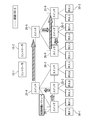
- the packet processing unit 23 transfers the packet (1st packet) to the controller 10-1 and the controller 10-2 that manage the switch 20-1.
- the route calculation unit 11 is based on the topology information of the network management unit 12 and the analysis result of the packet processing unit 13. The route that the packet (1st packet) should take is calculated.
- the route calculated by the controller 10-1 is assumed to be a route 100-1
- the route calculated by the controller 10-2 is assumed to be a route 100-2.
- the route 100-1 is “switch 20-1” ⁇ “switch 20-4” ⁇ “switch 20-5” ⁇ “switch 20-6” ⁇ “switch 20-7” ⁇ “switch 20-8” in this order. Become.
- the route 100-2 is “switch 20-1” ⁇ “switch 20-2” ⁇ “switch 20-4” ⁇ “switch 20-5” ⁇ “switch 20-7” ⁇ “switch 20-6” ⁇ “switch 20-8 ".
- the packet is prevented from being followed according to the flow entry 211 before the setting is completed.
- the packet is not transferred from the transmission source host 30-1 to the transmission destination host 30-2.
- the flow entry temporarily set there 211 may be held.
- Another method can be realized by having an area in which it is possible to determine whether the flow entry 211 is temporarily set or permanently registered.
- the controller 10 (10-i, i 1 to x) registers the flow entry 211 temporarily set in the switch 20-1 in the flow table 21.
- the switch 20-1 selects either one so that the adopted route becomes one.
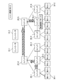
- the adopted route is the route 100-1 set by the controller 10-1.
- the switch 20-1 Since the controller 10-1 responded the earliest, the switch 20-1 notifies the controller 10-2 that has not been adopted that the route has not been adopted.
- the switch 20-1 deletes the flow entry 211 of the rejected route 100-2 set by the controller 10-2.
- the deletion of the unaccepted route 100-2 is performed using the route deletion packet 50.
- the switch 20-1 transmits a route deletion packet 50 toward the switch on the non-accepted route 100-2.
- a route deletion packet 50 flows through the non-adopted route 100-2.
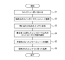
- Step S501 the packet processing unit 23 sets information of the rejected route 100-2 set by the controller 10-2 in the route deletion packet 50.
- the packet processing unit 23 creates the route deletion packet 50 based on the flow header 2111, the flow ID 2113 of the flow entry 211 of the non-adopted route 100-2, and the controller ID 2114 indicating the controller 10-2. That is, the flow header 51, the route ID 52, and the controller ID 53 of the route deletion packet 50 are equal to the flow header 2111, the route ID 2113, and the controller ID 2114 of the non-adopted route 100-2, respectively.
- Step S502 In the switch 20-1, the packet processing unit 23 checks whether the content of the action 2112 of the flow entry 211 of the non-accepted route 100-2 is the content to be transferred to the transmission destination host 30-2. That is, it is confirmed whether it is a switch at the end of the path.
- Step S503 In the switch 20-1, when the content of the action 2112 of the flow entry 211 is not the content to be transferred to the destination host 30-2, the packet processing unit 23 processes the route deletion packet 50 according to the action 2112 of the flow entry 211. Here, in the switch 20-1, the packet processing unit 23 transfers the route deletion packet 50 to the next-stage switch 20-2 in accordance with the action 2112 of the flow entry 211.
- the route deletion packet 50 is processed according to the action 2112 of the flow entry 211.
- a relay device such as a router in a compatible network
- the switch 20-7 cannot process the route deletion packet 50 because the flow entry 211 of the route 100-2 that has not been adopted is not set.
- the switch 20-7 temporarily holds the received route deletion packet 50.
- the reason why the route deletion packet 50 is temporarily held is that the registration process of the flow entry 211 may be delayed.
- the switch 20-7 is delayed by the controller 10-2 whose route is not adopted.
- the route deletion packet 50 received from the switch 20-5 is held.
- the switch 20-7 discards the registration of the flow entry 211.
- the switch 20-7 transmits the route deletion packet 50 to the next-stage switch 20-6 according to the flow entry 211 just in case. You may do it.
- the switch 20-6 receives the route deletion packet 50, the switch 20-6 performs the same processing as the switch 20-7.
- the switch 20-7 determines that there is no flow entry of the rejected route that should be discarded, and the route deletion packet 50 is Discard.
- the switch 20-1 sets the flow entry 211 temporarily set by the controller 10-1 that responded earliest in the flow table 21.
- the switch 20-1 processes the 1st packet according to the action 2112 of the corresponding flow entry 211.
- the switch 20-1 sets the temporary flow entry 211 in the flow table 21 after transferring the route deletion packet 50 to the switch 20-4.
- the switch 20-1 transfers the received packet to the switch 20-4 on the adopted route according to the flow entry 211.
- the switch 1 receives a packet from the host 1.
- the switch 1 If the switch 1 is a packet that does not match the flow entry held by itself, the switch 1 transfers the packet as a 1st packet to a plurality of controllers that control itself. Here, the switch 1 transfers the 1st packet to the controller 1 and the controller 2.
- the controller 1 and the controller 2 calculate a route and set a flow entry for each of the switches on the route. At this time, the controller 1 and the controller 2 perform flow entry setting for each of the switches on the path in order from the switch 1 that has received the 1st packet.
- information (flag or the like) indicating provisional setting is assigned to the flow entry set in the switch 1 that has received the 1st packet.
- the flow entry set in the switch 1 that has received the 1st packet is not a formally set flow entry but a provisionally set flow entry.
- the information indicating the temporary setting is information indicating that the flow entry is still invalid.
- the switch 1 that has received the 1st packet does not transfer the packet in accordance with the temporarily set flow entry. Note that an area for storing information indicating temporary setting may be newly provided in the flow entry, or a part of an existing area in the flow entry may be used.
- the controller 1 and the controller 2 transmit a notification that the setting is completed (setting completion notification), and the flow entry set in the switch 1 that has received the 1st packet The information indicating the temporary setting is removed from.
- the switch 1 that has received the 1st packet adopts the route set by the controller 1 that has completed the setting of all the switches earliest (first) as the packet communication route, and other than the controller 1 that adopted the route.
- a notice of rejection is sent to the controller 2.
- the controller 2 receives the non-employment notification, if the setting of the switch on the route is in the middle, the subsequent setting is stopped.
- the controller 2 receives a non-adoption notice and stops setting the switch 4 on the route.
- the switch 1 that has received the 1st packet generates a route deletion packet in order to delete the route that has not been adopted, and sends the route deletion packet to the adjacent switch 3 in accordance with the flow entry of the route that has not been adopted. Transfer and delete the flow entry of the route that was not adopted.
- a switch on the route that has not been adopted, including the switch 3 receives a route deletion packet, the switch is transferred to the adjacent switch 4 according to the flow entry that matches the header information of the route deletion packet, and then the flow entry is deleted. To do. Since the flow entry that matches the header information of the route deletion packet is not set, the switch 4 temporarily holds the route deletion packet and discards the route deletion packet after a predetermined time has elapsed.
- the switch 4 is identified as the last switch on the route that has not been adopted from the contents of the flow entry.
- the route deletion packet is not transmitted to the host 2, the flow entry that matches the header information of the route deletion packet is deleted, and the route deletion packet is discarded. Details of these processes are the same as the non-accepted route deletion process shown in FIG.
- the switch 1 that has received the 1st packet transfers the packets after the 1st packet to the adjacent switch 2 in accordance with the flow entry of the adopted route.
- the switch 2 forwards the first and subsequent packets to the adjacent switch 4 according to the flow entry.
- the last switch 4 on the adopted route transfers the packet after the 1st packet to the host 2 according to the flow entry of the adopted route.
- the switch that receives the 1st packet is controlled by two controllers, but control by three or more controllers can also be realized. That is, the two controllers shown in the figure indicate “a controller adopting a route” and “a controller not adopting a route”, and the number of individual controllers is arbitrary.
- the controller calculates a route (path) of a predetermined packet group (flow) “in advance (before data communication starts)”, and registers the flow entry in the flow table of the switch.
- the “Proactive type” here refers to “advanced flow entry registration” performed voluntarily by the controller.
- the controller calculates the route of the packet group (flow) when the switch receives an inquiry about the 1st packet (a new packet with no corresponding flow entry) from the switch, and flows to the flow table of the switch. Create an entry. That is, the “Reactive type” here refers to “real-time flow entry registration” performed by the controller in response to an inquiry from the switch during actual data communication.
- the “Reactive type” that registers the flow entry related to the received packet when the controller receives an inquiry about the 1st packet from the switch is the main.
- the “Proactive type” is suitable for reducing the processing frequency of the flow table and solving the performance problem.
- the “Proactive type” is more suitable for processing even when a large number of first packets arrive at the controller.
- the number of flow entries becomes enormous if the complete “Proactive type” is used, it may be possible to escape from the restriction on the number of flow entries by making a part of the “Reactive type”.
- the flow can be defined before the start of communication, so that it is considered possible to avoid the problem of mass flow due to viruses such as Nimda, unauthorized access due to unknown packets, and the like.
- each of a plurality of controllers calculates a route of a predetermined packet group that is expected to arrive without receiving a packet inquiry from the switch (before data communication starts), and switches on the route
- the flow entry may be registered in the flow table.
- the deletion process of the non-employed route in the switch is the same as that in the first embodiment.
- a network composed of network devices in which packet transfer and routing control functions are separated is targeted.
- a plurality of controllers operate independently, and flow entries can be set for all network devices without communication between the controllers.
- the route is a route set by a controller that has completed setting the earliest among a plurality of controllers.
- the network device generates a route deletion packet for deleting a flow entry of a route that is not used for communication.
- the network device transfers the route deletion packet to the adjacent network device on the route that is not used for communication.
- the network device when the network device receives the route deletion packet, the network device analyzes the route deletion packet and, based on the analysis result, out of the flow entries set in itself, the flow entry that matches the header information of the route deletion packet Is deleted.
- the network device when there is no flow entry that matches the route deletion packet, the network device temporarily holds the route deletion packet.
- the registration is discarded.
- a communication path can be set without synchronization between a plurality of controllers. Further, by deleting the non-accepted route, a closed circuit is not created on the network, and a failure that the transfer is not correctly performed to the transmission destination does not occur. In addition, the network device does not perform processing such as addition or deletion of information on the packet.
- Appendix 1 An apparatus for setting a flow entry in a flow table in which rules and operations for uniformly controlling a packet as a flow are defined based on control from each of a plurality of controllers; Adopt the route set by the controller that completed the setting of the flow entry of all the network devices on the route the earliest among multiple controllers, and reject the route set by other controllers, and the flow of the adopted route
- a network device comprising a device for transferring a packet according to an entry.
- (Appendix 2) The network device according to attachment 1, wherein An apparatus for receiving a setting completion notification indicating that the setting of all network devices on the route has been completed from each of the plurality of controllers; In response to the setting completion notification, a device that creates a route deletion packet that matches the flow entry of the rejected route, When a route deletion packet is received from the outside, a device that checks whether there is a flow entry that matches the route deletion packet, A device that transfers a route deletion packet to an adjacent network device on the rejected route according to the flow entry of the rejected route; A network device further comprising a device for deleting a flow entry of a rejected route.
- a path control method implemented by a network device Based on control from each of a plurality of controllers, setting a flow entry in which rules and operations for uniformly controlling a packet as a flow are defined in the flow table; Adopt the route set by the controller that completed the setting of the flow entry of all the network devices on the route the earliest among multiple controllers, and reject the route set by other controllers, and the flow of the adopted route
- a routing method comprising forwarding a packet according to an entry.
- a route control method further comprising: discarding a route deletion packet after a predetermined time has elapsed since holding.
- Appendix 10 The program according to appendix 9, wherein Receiving a setting completion notification from each of the plurality of controllers indicating that the setting of all network devices on the route has been completed; In response to the setting completion notification, creating a route deletion packet that matches the flow entry of the rejected route; When a route deletion packet is received from the outside, a step of confirming whether there is a flow entry that matches the route deletion packet; Transferring a route deletion packet to an adjacent program on the rejected route according to the flow entry of the rejected route; A program for causing a network device to further execute a step of deleting a flow entry of a rejected route.
Landscapes
- Engineering & Computer Science (AREA)
- Computer Networks & Wireless Communication (AREA)
- Signal Processing (AREA)
- Data Exchanges In Wide-Area Networks (AREA)
Abstract
Selon la présente invention, dans un réseau constitué par des dispositifs réseau dont les fonctions de commande sont séparées sur des contrôleurs externes, comme exemplifié par un réseau OpenFlow, un chemin qui n'est pas adopté peut être supprimé lorsque les contrôleurs sont multiplexés/redondants. Spécifiquement, un dispositif réseau détermine une entrée de flux dans laquelle une règle et une opération permettant de commander uniformément des paquets sous la forme d'un flux sont définies, dans une table de flux, sur la base du contrôle de chaque contrôleur d'une pluralité de contrôleurs. À ce stade, un chemin sélectionné par un contrôleur qui a fini de déterminer les entrées de flux concernant tous les dispositifs réseau placés sur le chemin, le tout premier parmi la pluralité de contrôleurs, est adopté et les chemins sélectionnés par les autres contrôleurs ne sont pas adoptés, et les paquets sont transférés selon l'entrée de flux du chemin adopté.
Priority Applications (1)
| Application Number | Priority Date | Filing Date | Title |
|---|---|---|---|
| JP2013503488A JP5495150B2 (ja) | 2011-03-04 | 2012-03-01 | ネットワークシステム、ネットワーク機器、及び経路制御方法 |
Applications Claiming Priority (2)
| Application Number | Priority Date | Filing Date | Title |
|---|---|---|---|
| JP2011-048143 | 2011-03-04 | ||
| JP2011048143 | 2011-03-04 |
Publications (1)
| Publication Number | Publication Date |
|---|---|
| WO2012121114A1 true WO2012121114A1 (fr) | 2012-09-13 |
Family
ID=46798080
Family Applications (1)
| Application Number | Title | Priority Date | Filing Date |
|---|---|---|---|
| PCT/JP2012/055272 Ceased WO2012121114A1 (fr) | 2011-03-04 | 2012-03-01 | Système de réseau, dispositif réseau et procédé de commande de chemin |
Country Status (2)
| Country | Link |
|---|---|
| JP (1) | JP5495150B2 (fr) |
| WO (1) | WO2012121114A1 (fr) |
Cited By (3)
| Publication number | Priority date | Publication date | Assignee | Title |
|---|---|---|---|---|
| CN103874078A (zh) * | 2014-02-14 | 2014-06-18 | 北京邮电大学 | 一种移动通信接入网架构 |
| KR20160028250A (ko) * | 2014-09-03 | 2016-03-11 | 주식회사 케이티 | 소프트웨어 정의 네트워크에서 컨트롤러의 이중화 제어 시스템 및 그 방법 |
| JP2016530806A (ja) * | 2013-08-13 | 2016-09-29 | 華為技術有限公司Huawei Technologies Co.,Ltd. | 無線アクセス方法、装置およびシステム |
Families Citing this family (1)
| Publication number | Priority date | Publication date | Assignee | Title |
|---|---|---|---|---|
| JP5935873B2 (ja) * | 2012-03-05 | 2016-06-15 | 日本電気株式会社 | ネットワークシステム、スイッチ、及びネットワーク構築方法 |
Citations (1)
| Publication number | Priority date | Publication date | Assignee | Title |
|---|---|---|---|---|
| WO2010103909A1 (fr) * | 2009-03-09 | 2010-09-16 | 日本電気株式会社 | SYSTÈME DE COMMUNICATION OpenFlow ET PROCÉDÉ DE COMMUNICATION OpenFlow |
Family Cites Families (1)
| Publication number | Priority date | Publication date | Assignee | Title |
|---|---|---|---|---|
| JP5488980B2 (ja) * | 2010-02-08 | 2014-05-14 | 日本電気株式会社 | コンピュータシステム、及び通信方法 |
-
2012
- 2012-03-01 WO PCT/JP2012/055272 patent/WO2012121114A1/fr not_active Ceased
- 2012-03-01 JP JP2013503488A patent/JP5495150B2/ja not_active Expired - Fee Related
Patent Citations (1)
| Publication number | Priority date | Publication date | Assignee | Title |
|---|---|---|---|---|
| WO2010103909A1 (fr) * | 2009-03-09 | 2010-09-16 | 日本電気株式会社 | SYSTÈME DE COMMUNICATION OpenFlow ET PROCÉDÉ DE COMMUNICATION OpenFlow |
Non-Patent Citations (1)
| Title |
|---|
| "OpenFlow Switch Specification, Version 1.1.0 Implemented", 28 February 2011 (2011-02-28), Retrieved from the Internet <URL:http://www.openflow.org/documents/openflow-spec-v1.1.0,pdf> [retrieved on 20120323] * |
Cited By (6)
| Publication number | Priority date | Publication date | Assignee | Title |
|---|---|---|---|---|
| JP2016530806A (ja) * | 2013-08-13 | 2016-09-29 | 華為技術有限公司Huawei Technologies Co.,Ltd. | 無線アクセス方法、装置およびシステム |
| US10250674B2 (en) | 2013-08-13 | 2019-04-02 | Huawei Technologies Co., Ltd. | Radio access method, apparatus, and system for implementing mutual transmission and processing of collaborative data between sites |
| CN103874078A (zh) * | 2014-02-14 | 2014-06-18 | 北京邮电大学 | 一种移动通信接入网架构 |
| CN103874078B (zh) * | 2014-02-14 | 2017-05-31 | 北京邮电大学 | 一种移动通信接入网架构 |
| KR20160028250A (ko) * | 2014-09-03 | 2016-03-11 | 주식회사 케이티 | 소프트웨어 정의 네트워크에서 컨트롤러의 이중화 제어 시스템 및 그 방법 |
| KR102251407B1 (ko) | 2014-09-03 | 2021-05-12 | 주식회사 케이티 | 소프트웨어 정의 네트워크에서 컨트롤러의 이중화 제어 시스템 및 그 방법 |
Also Published As
| Publication number | Publication date |
|---|---|
| JP5495150B2 (ja) | 2014-05-21 |
| JPWO2012121114A1 (ja) | 2014-07-17 |
Similar Documents
| Publication | Publication Date | Title |
|---|---|---|
| JP5842933B2 (ja) | ネットワークシステム、及び経路情報同期方法 | |
| JP5610247B2 (ja) | ネットワークシステム、及びポリシー経路設定方法 | |
| JP5935873B2 (ja) | ネットワークシステム、スイッチ、及びネットワーク構築方法 | |
| JP5594552B2 (ja) | ネットワークシステム、及び経路制御方法 | |
| JP5846221B2 (ja) | ネットワークシステム、及びトポロジー管理方法 | |
| RU2583745C2 (ru) | Сетевая система, коммутатор и способ обнаружения подсоединенного терминала | |
| JP5747993B2 (ja) | 負荷低減システム、及び負荷低減方法 | |
| CN103621027B (zh) | 通信路由控制系统和通信路由控制方法 | |
| JP2011160363A (ja) | コンピュータシステム、コントローラ、スイッチ、及び通信方法 | |
| JP5495150B2 (ja) | ネットワークシステム、ネットワーク機器、及び経路制御方法 | |
| JP5682846B2 (ja) | ネットワークシステム、パケット処理方法、及び記憶媒体 | |
| JP5966488B2 (ja) | ネットワークシステム、スイッチ、及び通信遅延短縮方法 | |
| JP2013115733A (ja) | ネットワークシステム、及びネットワーク制御方法 | |
| JP2015511097A (ja) | 通信システム、制御装置、通信方法、及びプログラム |
Legal Events
| Date | Code | Title | Description |
|---|---|---|---|
| 121 | Ep: the epo has been informed by wipo that ep was designated in this application |
Ref document number: 12754955 Country of ref document: EP Kind code of ref document: A1 |
|
| ENP | Entry into the national phase |
Ref document number: 2013503488 Country of ref document: JP Kind code of ref document: A |
|
| NENP | Non-entry into the national phase |
Ref country code: DE |
|
| 122 | Ep: pct application non-entry in european phase |
Ref document number: 12754955 Country of ref document: EP Kind code of ref document: A1 |