WO2012121241A1 - Matériau actif d'électrode négative pour dispositif électrique et dispositif électrique - Google Patents
Matériau actif d'électrode négative pour dispositif électrique et dispositif électrique Download PDFInfo
- Publication number
- WO2012121241A1 WO2012121241A1 PCT/JP2012/055667 JP2012055667W WO2012121241A1 WO 2012121241 A1 WO2012121241 A1 WO 2012121241A1 JP 2012055667 W JP2012055667 W JP 2012055667W WO 2012121241 A1 WO2012121241 A1 WO 2012121241A1
- Authority
- WO
- WIPO (PCT)
- Prior art keywords
- mass
- negative electrode
- active material
- electrode active
- less
- Prior art date
- Legal status (The legal status is an assumption and is not a legal conclusion. Google has not performed a legal analysis and makes no representation as to the accuracy of the status listed.)
- Ceased
Links
Images


Classifications
-
- H—ELECTRICITY
- H01—ELECTRIC ELEMENTS
- H01M—PROCESSES OR MEANS, e.g. BATTERIES, FOR THE DIRECT CONVERSION OF CHEMICAL ENERGY INTO ELECTRICAL ENERGY
- H01M4/00—Electrodes
- H01M4/02—Electrodes composed of, or comprising, active material
- H01M4/36—Selection of substances as active materials, active masses, active liquids
- H01M4/38—Selection of substances as active materials, active masses, active liquids of elements or alloys
- H01M4/386—Silicon or alloys based on silicon
-
- H—ELECTRICITY
- H01—ELECTRIC ELEMENTS
- H01M—PROCESSES OR MEANS, e.g. BATTERIES, FOR THE DIRECT CONVERSION OF CHEMICAL ENERGY INTO ELECTRICAL ENERGY
- H01M4/00—Electrodes
- H01M4/02—Electrodes composed of, or comprising, active material
- H01M4/36—Selection of substances as active materials, active masses, active liquids
- H01M4/38—Selection of substances as active materials, active masses, active liquids of elements or alloys
-
- C—CHEMISTRY; METALLURGY
- C22—METALLURGY; FERROUS OR NON-FERROUS ALLOYS; TREATMENT OF ALLOYS OR NON-FERROUS METALS
- C22C—ALLOYS
- C22C28/00—Alloys based on a metal not provided for in groups C22C5/00 - C22C27/00
-
- C—CHEMISTRY; METALLURGY
- C22—METALLURGY; FERROUS OR NON-FERROUS ALLOYS; TREATMENT OF ALLOYS OR NON-FERROUS METALS
- C22C—ALLOYS
- C22C30/00—Alloys containing less than 50% by weight of each constituent
-
- H—ELECTRICITY
- H01—ELECTRIC ELEMENTS
- H01G—CAPACITORS; CAPACITORS, RECTIFIERS, DETECTORS, SWITCHING DEVICES, LIGHT-SENSITIVE OR TEMPERATURE-SENSITIVE DEVICES OF THE ELECTROLYTIC TYPE
- H01G4/00—Fixed capacitors; Processes of their manufacture
- H01G4/002—Details
- H01G4/005—Electrodes
- H01G4/008—Selection of materials
-
- H—ELECTRICITY
- H01—ELECTRIC ELEMENTS
- H01M—PROCESSES OR MEANS, e.g. BATTERIES, FOR THE DIRECT CONVERSION OF CHEMICAL ENERGY INTO ELECTRICAL ENERGY
- H01M10/00—Secondary cells; Manufacture thereof
- H01M10/05—Accumulators with non-aqueous electrolyte
- H01M10/052—Li-accumulators
- H01M10/0525—Rocking-chair batteries, i.e. batteries with lithium insertion or intercalation in both electrodes; Lithium-ion batteries
-
- H—ELECTRICITY
- H01—ELECTRIC ELEMENTS
- H01M—PROCESSES OR MEANS, e.g. BATTERIES, FOR THE DIRECT CONVERSION OF CHEMICAL ENERGY INTO ELECTRICAL ENERGY
- H01M4/00—Electrodes
- H01M4/02—Electrodes composed of, or comprising, active material
- H01M4/13—Electrodes for accumulators with non-aqueous electrolyte, e.g. for lithium-accumulators; Processes of manufacture thereof
-
- H—ELECTRICITY
- H01—ELECTRIC ELEMENTS
- H01M—PROCESSES OR MEANS, e.g. BATTERIES, FOR THE DIRECT CONVERSION OF CHEMICAL ENERGY INTO ELECTRICAL ENERGY
- H01M4/00—Electrodes
- H01M4/02—Electrodes composed of, or comprising, active material
- H01M4/36—Selection of substances as active materials, active masses, active liquids
- H01M4/38—Selection of substances as active materials, active masses, active liquids of elements or alloys
- H01M4/46—Alloys based on magnesium or aluminium
-
- H—ELECTRICITY
- H01—ELECTRIC ELEMENTS
- H01M—PROCESSES OR MEANS, e.g. BATTERIES, FOR THE DIRECT CONVERSION OF CHEMICAL ENERGY INTO ELECTRICAL ENERGY
- H01M4/00—Electrodes
- H01M4/02—Electrodes composed of, or comprising, active material
- H01M4/36—Selection of substances as active materials, active masses, active liquids
- H01M4/38—Selection of substances as active materials, active masses, active liquids of elements or alloys
- H01M4/46—Alloys based on magnesium or aluminium
- H01M4/463—Aluminium based
-
- B—PERFORMING OPERATIONS; TRANSPORTING
- B22—CASTING; POWDER METALLURGY
- B22F—WORKING METALLIC POWDER; MANUFACTURE OF ARTICLES FROM METALLIC POWDER; MAKING METALLIC POWDER; APPARATUS OR DEVICES SPECIALLY ADAPTED FOR METALLIC POWDER
- B22F2998/00—Supplementary information concerning processes or compositions relating to powder metallurgy
-
- C—CHEMISTRY; METALLURGY
- C22—METALLURGY; FERROUS OR NON-FERROUS ALLOYS; TREATMENT OF ALLOYS OR NON-FERROUS METALS
- C22C—ALLOYS
- C22C21/00—Alloys based on aluminium
- C22C21/02—Alloys based on aluminium with silicon as the next major constituent
-
- H—ELECTRICITY
- H01—ELECTRIC ELEMENTS
- H01M—PROCESSES OR MEANS, e.g. BATTERIES, FOR THE DIRECT CONVERSION OF CHEMICAL ENERGY INTO ELECTRICAL ENERGY
- H01M10/00—Secondary cells; Manufacture thereof
- H01M10/05—Accumulators with non-aqueous electrolyte
- H01M10/052—Li-accumulators
-
- Y—GENERAL TAGGING OF NEW TECHNOLOGICAL DEVELOPMENTS; GENERAL TAGGING OF CROSS-SECTIONAL TECHNOLOGIES SPANNING OVER SEVERAL SECTIONS OF THE IPC; TECHNICAL SUBJECTS COVERED BY FORMER USPC CROSS-REFERENCE ART COLLECTIONS [XRACs] AND DIGESTS
- Y02—TECHNOLOGIES OR APPLICATIONS FOR MITIGATION OR ADAPTATION AGAINST CLIMATE CHANGE
- Y02E—REDUCTION OF GREENHOUSE GAS [GHG] EMISSIONS, RELATED TO ENERGY GENERATION, TRANSMISSION OR DISTRIBUTION
- Y02E60/00—Enabling technologies; Technologies with a potential or indirect contribution to GHG emissions mitigation
- Y02E60/10—Energy storage using batteries
-
- Y—GENERAL TAGGING OF NEW TECHNOLOGICAL DEVELOPMENTS; GENERAL TAGGING OF CROSS-SECTIONAL TECHNOLOGIES SPANNING OVER SEVERAL SECTIONS OF THE IPC; TECHNICAL SUBJECTS COVERED BY FORMER USPC CROSS-REFERENCE ART COLLECTIONS [XRACs] AND DIGESTS
- Y02—TECHNOLOGIES OR APPLICATIONS FOR MITIGATION OR ADAPTATION AGAINST CLIMATE CHANGE
- Y02T—CLIMATE CHANGE MITIGATION TECHNOLOGIES RELATED TO TRANSPORTATION
- Y02T10/00—Road transport of goods or passengers
- Y02T10/60—Other road transportation technologies with climate change mitigation effect
- Y02T10/70—Energy storage systems for electromobility, e.g. batteries
Definitions
- the present invention relates to a negative electrode active material for electric devices, a negative electrode for electric devices, and an electric device. More specifically, the electric device of the present invention is used as a driving power source or auxiliary power source for a motor in a vehicle such as an electric vehicle, a fuel cell vehicle, and a hybrid electric vehicle, for example, as a secondary battery or a capacitor.
- Lithium ion secondary batteries are generally formed by applying a positive electrode slurry containing a positive electrode active material on the surface of a current collector and a negative electrode slurry containing a negative electrode active material on the surface of the current collector. A negative electrode and an electrolyte layer located between them are provided. And a lithium ion secondary battery has the structure by which these positive electrodes, the negative electrode, and the electrolyte layer were accommodated in the battery case.
- Patent Document 1 a material described in Patent Document 1 has been proposed as a negative electrode material for a lithium secondary battery that exhibits excellent cycle characteristics while maintaining a high discharge capacity.
- the negative electrode material for a lithium secondary battery in Patent Document 1 is a material made of a composite powder having a predetermined particle size, which is composed of a plurality of types of metal components, a carbon component made of a fine carbon material, and the like.
- the negative electrode material for a lithium secondary battery described in Patent Document 1 has a problem that the discharge capacity and the cycle characteristics are not sufficient.
- the present invention has been made in view of such problems of the conventional technology. And the objective is to provide the negative electrode active material for electric devices which can exhibit the outstanding cycling characteristics, maintaining the high discharge capacity, the negative electrode for electric devices using the same, and an electric device.
- the negative electrode active material for an electric device includes more than 27 mass% and less than 100 mass% silicon, more than 0 mass% and less than 73 mass% aluminum, and more than 0 mass% and less than 58 mass% niobium. It has an alloy that contains and the balance is inevitable impurities.
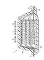
- FIG. 1 is a schematic cross-sectional view showing an example of a lithium ion secondary battery according to an embodiment of the present invention.
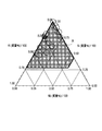
- FIG. 2 is a plot of each example in the composition diagram of the Si—Al—Nb ternary alloy, 0.27 ⁇ Si (mass% / 100) ⁇ 1.00, 0.00 ⁇ Al (mass% / 100) ⁇ 0.73, 0.00 ⁇ Nb (mass% / 100) ⁇ 0.58.
- FIG. 1 is a schematic cross-sectional view showing an example of a lithium ion secondary battery according to an embodiment of the present invention.
- FIG. 2 is a plot of each example in the composition diagram of the Si—Al—Nb ternary alloy, 0.27 ⁇ Si (mass% / 100) ⁇ 1.00, 0.00 ⁇ Al (mass% / 100) ⁇ 0.73, 0.00 ⁇ Nb (mass% / 100) ⁇ 0.58.
- FIG. 1 is a schematic cross-sectional view
- FIG. 3 is a plot of each example in the composition diagram of the Si—Al—Nb ternary alloy, 0.47 ⁇ Si (mass% / 100) ⁇ 0.95, 0.02 ⁇ Al (mass% / 100) ⁇ 0.48, 0.01 ⁇ Nb (mass% / 100) ⁇ 0.23.
- FIG. 1 is a plot of each example in the composition diagram of the Si—Al—Nb ternary alloy, 0.47 ⁇ Si (mass% / 100) ⁇ 0.95, 0.02 ⁇ Al (mass% / 100) ⁇ 0.48, 0.01 ⁇ Nb (mass% / 100) ⁇ 0.23.
- the negative electrode active material for electric devices of the present invention the negative electrode for electric devices using the same, and the electric device will be described in detail.
- a negative electrode active material for an electric device, a negative electrode for an electric device, and an electric device will be described by taking a lithium ion secondary battery as an example of an electric device to which the negative electrode active material can be applied as an example.
- the dimensional ratios in the drawings are exaggerated for convenience of explanation, and may differ from actual ratios.
- the negative electrode active material of the present embodiment includes more than 27 mass% and less than 100 mass% silicon (Si), more than 0 mass% and less than 73 mass% aluminum (Al), and more than 0 mass% and less than 58 mass% niobium ( Nb) and the balance is an inevitable impurity alloy.
- This numerical range corresponds to the range indicated by the symbol A in FIG.
- a lithium ion secondary battery can exhibit excellent cycle characteristics while maintaining a high discharge capacity as compared with a carbon-based negative electrode active material having a charge / discharge capacity of about 300 mAh / g.
- a lithium ion secondary battery It is suitably used for a negative electrode.
- it can be suitably used as a lithium-ion secondary battery for vehicle drive power or auxiliary power.
- the present invention can be sufficiently applied to lithium ion secondary batteries for portable devices such as mobile phones.
- the alloy absorbs lithium ions when the battery is charged and releases lithium ions when discharged.
- the negative electrode active material contains aluminum (Al) as a first additive element that suppresses amorphous-crystal phase transition and improves cycle life when alloyed with lithium by charging. Further, it contains niobium (Nb) as a second additive element that makes it difficult to reduce the capacitance as an electrode even if the concentration of the first additive element is increased.
- the negative electrode active material of the Si (Si—Al—Nb-based) alloy according to this embodiment can exhibit high capacity, high cycle durability, and high charge / discharge efficiency in the initial stage. Can do.
- the negative electrode active material made of a Si—Al—Nb-based alloy a sufficient initial capacity may not be obtained when the silicon content is 27% by mass or less, and conversely, when the silicon content is 100% by mass. Can obtain only the same cycle characteristics as in the case of conventional pure silicon.
- the cycle characteristics are equivalent to pure silicon when the content is 0% by mass, and conversely, when the content is 73% by mass or more, the silicon content is relatively decreased, the initial capacity is There is a tendency to deteriorate compared with existing negative electrode active materials.
- the cycle characteristics are equivalent to that of pure silicon, and conversely, when the content is 58% by mass or more, the silicon content decreases, so the initial capacity is the existing negative electrode. There is a tendency to get worse compared to the active material.
- the alloy has an Si content of more than 47% by mass and less than 95% by mass, an Al content of more than 2% by mass and less than 48% by mass, and Nb content. It is preferable that the amount is more than 1% by mass and less than 23% by mass and the balance is inevitable impurities. That is, this numerical range corresponds to the range indicated by the symbol B in FIG.
- the alloy has an Si content of more than 61% by mass and less than 84% by mass, an Al content of more than 2% by mass and less than 25% by mass, and Nb content.
- the amount is preferably more than 2% by mass and less than 23% by mass, and the balance is inevitable impurities. This numerical range corresponds to the range indicated by the symbol C in FIG.
- the Si content is more than 47% by mass and less than 56% by mass
- the Al content is more than 33% by mass and less than 48% by mass
- the Nb content is more than 1% by mass and less than 16% by mass
- the inevitable impurities may vary depending on the raw materials and the production method, but the content thereof is preferably less than 0.5% by mass, for example, and more preferably less than 0.1% by mass.
- the alloy contained in the negative electrode active material of the present embodiment is, as described above, more than 27 mass% and less than 100 mass% silicon, more than 0 mass% and less than 73 mass% aluminum, and more than 0 mass% and more than 58 mass%. % Of niobium and the balance is inevitable impurities. Therefore, in other words, the alloy consists of more than 27% by mass of silicon and less than 100% by mass of silicon, more than 0% by mass of less than 73% by mass of aluminum, more than 0% by mass of less than 58% by mass of niobium, and inevitable impurities. Is.
- an alloy in a thin film state can be cited.
- a method for producing such an alloy for example, a multi-source physical vapor deposition method (multi-source PVD method) such as a sputtering method, a resistance heating method, or a laser ablation method, or a multi-source chemical vapor deposition method such as a chemical vapor deposition method ( Multi-source CVD method).
- multi-source PVD method multi-source physical vapor deposition method
- a sputtering method such as a sputtering method, a resistance heating method, or a laser ablation method
- a multi-source chemical vapor deposition method such as a chemical vapor deposition method ( Multi-source CVD method).
- the negative electrode active material such as a binder and a conductive additive. Therefore, it is excellent in the viewpoint that the high capacity
- an independently controlled ternary DC magnetron sputtering apparatus can be used as a multi-element DC magnetron sputtering apparatus.
- a thin film of a silicon alloy containing a predetermined amount of Si, Al, and Nb with various alloy compositions and thicknesses can be freely formed on the surface of the substrate serving as a current collector.
- various alloys can be obtained by setting the target 1 to silicon (Si), the target 2 to aluminum (Al), the target 3 to niobium (Nb), fixing the sputtering time, and changing the power of the DC power source. it can.
- various alloys can be obtained by changing the power of the DC power source to 185 W for silicon (Si), 30 to 120 W for aluminum (Al), 60 to 120 W for niobium (Nb), and the like.
- the power of the DC power source to 185 W for silicon (Si), 30 to 120 W for aluminum (Al), 60 to 120 W for niobium (Nb), and the like.
- the sputtering conditions differ for each sputtering apparatus, it is desirable to appropriately grasp a suitable range through preliminary experiments for each sputtering apparatus.
- the Si—Al—Nb alloy thin film can be used for the negative electrode active material layer of the present embodiment.
- the negative electrode active material layer can also be a layer containing particles of the Si—Al—Nb alloy. That is, as another example of the negative electrode active material for a lithium ion secondary battery according to the present embodiment, for example, an alloy in a particle form can be cited.
- Examples of a method for producing such a particle-shaped alloy include a mechanical alloy method and an arc plasma melting method. Particles obtained by such a production method can be prepared by adding a binder, a conductive aid, a viscosity adjusting solvent, etc. to prepare a slurry, and applying this slurry to a current collector to form a negative electrode.
- This production method is superior to the above-described method for producing an alloy thin film in that it is easy to mass-produce and is practically used as an actual battery electrode.
- the manufacturing method of the negative electrode active material for a lithium ion secondary battery is not limited to these, and various conventionally known manufacturing methods can be applied. That is, since there is almost no difference in the alloy state and characteristics depending on the manufacturing method, various manufacturing methods can be applied.
- FIG. 1 is a schematic cross-sectional view showing an example of a lithium ion secondary battery according to an embodiment of the present invention.
- the lithium ion secondary battery 1 of this embodiment has a configuration in which a battery element 10 to which a positive electrode tab 21 and a negative electrode tab 22 are attached is enclosed in an exterior body 30.
- the positive electrode tab 21 and the negative electrode tab 22 are led out in the opposite direction from the inside of the exterior body 30 to the outside.
- the positive electrode tab and the negative electrode tab may be led out in the same direction from the inside of the exterior body toward the outside.
- such a positive electrode tab and a negative electrode tab can be attached to the positive electrode collector and negative electrode collector which are mentioned later by ultrasonic welding, resistance welding, etc., for example.
- the positive electrode tab 21 and the negative electrode tab 22 are made of materials such as aluminum, copper, titanium, nickel, stainless steel (SUS), and alloys thereof. However, the material is not limited to these, and a conventionally known material used as a tab for a lithium ion secondary battery can be used.
- the positive electrode tab and the negative electrode tab may be made of the same material or different materials. Further, as in the present embodiment, a separately prepared tab may be connected to a positive electrode current collector and a negative electrode current collector described later, and each positive electrode current collector and each negative electrode current collector described later are extended. A tab may be formed. Although not shown, the positive electrode tab 21 and the negative electrode tab 22 taken out from the outer package 30 are preferably covered with a heat-shrinkable heat-shrinkable tube or the like. Thereby, the possibility that the positive electrode tab 21 and the negative electrode tab 22 may contact a peripheral device, wiring, or the like to cause an electric leakage, thereby affecting products (for example, automobile parts, particularly electronic devices) is reduced.
- a current collector plate may be used for the purpose of taking out the current outside the battery.
- the current collector plate is electrically connected to the current collector and leads, and is taken out of the laminate sheet as the exterior body 30.
- the material which comprises a current collector plate is not specifically limited, The well-known highly electroconductive material conventionally used as a current collector plate for lithium ion secondary batteries can be used.
- As a constituent material of the current collector plate for example, metal materials such as aluminum, copper, titanium, nickel, stainless steel (SUS), and alloys thereof are preferable, and aluminum and aluminum are more preferable from the viewpoint of light weight, corrosion resistance, and high conductivity. Copper or the like is preferable.
- the same material may be used for a positive electrode current collecting plate and a negative electrode current collecting plate, and a different material may be used.
- the exterior body 30 is preferably formed of a film-shaped exterior material from the viewpoint of size reduction and weight reduction.
- the conventionally well-known material used for the exterior body for lithium ion secondary batteries can be used. That is, a metal can case can also be applied.
- a polymer-metal composite laminate sheet having excellent thermal conductivity is used from the viewpoint that it has high output and excellent cooling performance and can be suitably used for batteries for large equipment of electric vehicles and hybrid electric vehicles.
- an exterior body formed of an exterior material such as a laminate film having a three-layer structure in which PP, aluminum, and nylon are laminated in this order can be applied.
- the battery element 10 includes both a positive electrode 11 having a positive electrode active material layer 11b formed on both main surfaces of the positive electrode current collector 11a, an electrolyte layer 13, and a negative electrode current collector 12a.
- a plurality of negative electrodes 12 each having a negative electrode active material layer 12b formed on the main surface are stacked.
- the formed negative electrode active material layer 12 b faces through the electrolyte layer 13.
- a plurality of positive electrodes, electrolyte layers, and negative electrodes are laminated in this order.
- the adjacent positive electrode active material layer 11b, the electrolyte layer 13, and the negative electrode active material layer 12b constitute one unit cell layer. Therefore, the lithium ion secondary battery 1 of the present embodiment has a configuration in which a plurality of single battery layers 14 are stacked and electrically connected in parallel.
- the negative electrode current collector 12 a located in the outermost layer of the battery element 10 has a negative electrode active material layer 12 b formed only on one side.
- an insulating layer may be provided on the outer periphery of the unit cell layer in order to insulate between the adjacent positive electrode current collector and negative electrode current collector.
- Such an insulating layer is preferably formed on the outer periphery of the unit cell layer by a material that holds the electrolyte contained in the electrolyte layer and prevents the electrolyte from leaking.
- general-purpose plastics such as polypropylene (PP), polyethylene (PE), polyurethane (PUR), polyamide resin (PA), polytetrafluoroethylene (PTFE), polyvinylidene fluoride (PVdF), polystyrene (PS), etc.
- thermoplastic olefin rubber can be used. Silicone rubber can also be used.
- the positive electrode current collector 11a and the negative electrode current collector 12a are made of a conductive material.
- the size of the current collector can be determined according to the intended use of the battery. For example, if it is used for a large battery that requires a high energy density, a current collector having a large area is used. There is no particular limitation on the thickness of the current collector.
- the thickness of the current collector is usually about 1 to 100 ⁇ m.
- the shape of the current collector is not particularly limited. In the battery element 10 shown in FIG. 1, in addition to the current collector foil, a mesh shape (expanded grid or the like) can be used.
- a mesh shape expansion grid or the like
- a metal or a resin in which a conductive filler is added to a conductive polymer material or a non-conductive polymer material can be employed.
- the metal include aluminum, nickel, iron, stainless steel, titanium, and copper.
- covered on the metal surface may be sufficient.
- aluminum, stainless steel, copper, and nickel are preferable from the viewpoints of electronic conductivity, battery operating potential, and adhesion of the negative electrode active material by sputtering to the current collector.
- the conductive polymer material examples include polyaniline, polypyrrole, polythiophene, polyacetylene, polyparaphenylene, polyphenylene vinylene, polyacrylonitrile, and polyoxadiazole. Since such a conductive polymer material has sufficient conductivity without adding a conductive filler, it is advantageous in terms of facilitating the manufacturing process or reducing the weight of the current collector.
- Non-conductive polymer materials include, for example, polyethylene (PE; high density polyethylene (HDPE), low density polyethylene (LDPE), etc.), polypropylene (PP), polyethylene terephthalate (PET), polyether nitrile (PEN), polyimide (PI), polyamideimide (PAI), polyamide (PA), polytetrafluoroethylene (PTFE), styrene-butadiene rubber (SBR), polyacrylonitrile (PAN), polymethyl acrylate (PMA), polymethyl methacrylate (PMMA) , Polyvinyl chloride (PVC), polyvinylidene fluoride (PVdF), polystyrene (PS), and the like.
- PE polyethylene
- HDPE high density polyethylene
- LDPE low density polyethylene
- PP polypropylene
- PET polyethylene terephthalate
- PEN polyether nitrile
- PI polyimide
- PAI polyamideimide
- PA polyamide
- PTFE polyt
- a conductive filler can be added to the conductive polymer material or the non-conductive polymer material as necessary.
- a conductive filler is essential to impart conductivity to the resin.
- the conductive filler can be used without particular limitation as long as it is a substance having conductivity.
- a metal, conductive carbon, etc. are mentioned as a material excellent in electroconductivity, electric potential resistance, or lithium ion interruption
- the metal is not particularly limited, but includes at least one metal selected from the group consisting of Ni, Ti, Al, Cu, Pt, Fe, Cr, Sn, Zn, In, Sb, and K, or these metals.
- the conductive carbon is not particularly limited, but preferably acetylene black, Vulcan (registered trademark), black pearl (registered trademark), carbon nanofiber, ketjen black (registered trademark), carbon nanotube, carbon nanohorn, carbon It contains at least one selected from the group consisting of nanoballoons and fullerenes.
- the amount of the conductive filler added is not particularly limited as long as it is an amount capable of imparting sufficient conductivity to the current collector, and is generally about 5 to 35% by mass of the entire current collector.
- the material is not limited to these, and a conventionally known material used as a current collector for a lithium ion secondary battery can be used.
- the negative electrode active material according to this embodiment contains a Si—Al—Nb alloy having the above-described composition as an essential component.
- the negative electrode active material layer 12b according to this embodiment may be a thin film made of the Si—Al—Nb alloy.
- the negative electrode active material layer 12b may be formed of only the Si—Al—Nb alloy, or may contain other negative electrode active materials described later.
- the negative electrode active material layer 12b may be a layer containing particles of the Si—Al—Nb alloy as a main component.
- the negative electrode active material layer 12b may contain a conductive additive or a binder.
- the “main component” refers to a component having a content of 50% by mass or more in the negative electrode active material layer 12b.
- a negative electrode active material made of a Si—Al—Nb alloy having the above composition is used.
- the negative electrode active material made of such an alloy is contained as an essential component, there is no problem in using a conventionally known negative electrode active material capable of reversibly occluding and releasing lithium.
- negative electrode active materials include, for example, graphite (natural graphite, artificial graphite, etc.) which is highly crystalline carbon, low crystalline carbon (soft carbon, hard carbon), carbon black (Ketjen Black (registered trademark), acetylene) Black, channel black, lamp black, oil furnace black, thermal black, etc.), fullerenes, carbon nanotubes, carbon nanofibers, carbon nanohorns, carbon fibrils, and the like.
- a negative electrode active material Si, Ge, Sn, Pb, Al, In, Zn, H, Ca, Sr, Ba, Ru, Rh, Ir, Pd, Pt, Ag, Au, Cd, Hg, Ga
- examples thereof include simple elements such as Tl, C, N, Sb, Bi, O, S, Se, Te, and Cl that are alloyed with lithium, oxides and carbides containing these elements, and the like.
- oxides include silicon monoxide (SiO), SiOx (0 ⁇ x ⁇ 2), tin dioxide (SnO 2 ), SnO x (0 ⁇ x ⁇ 2), SnSiO 3 and the like.
- the carbide include silicon carbide (SiC).
- examples of the negative electrode active material include metal materials such as lithium metal and lithium-transition metal composite oxides such as lithium-titanium composite oxide (lithium titanate: Li 4 Ti 5 O 12 ).
- metal materials such as lithium metal and lithium-transition metal composite oxides such as lithium-titanium composite oxide (lithium titanate: Li 4 Ti 5 O 12 ).
- lithium-titanium composite oxide lithium titanate: Li 4 Ti 5 O 12
- the conventionally well-known material used as a negative electrode active material for lithium ion secondary batteries can be used. These negative electrode active materials may be used alone or in combination of two or more.
- the binder is not particularly limited, and examples thereof include the following materials.
- polyethylene PE
- polypropylene PP
- PET polyethylene terephthalate
- PEN polyether nitrile
- PAN polyacrylonitrile
- PA polyamide
- CMC carboxymethyl cellulose
- PVC polyvinyl chloride
- SBR styrene / butadiene rubber
- isoprene rubber butadiene rubber
- ethylene / propylene rubber ethylene / propylene / diene copolymer
- styrene / butadiene / styrene block copolymer examples thereof include thermoplastic polymers such as a polymer and a hydrogenated product thereof, a styrene / isoprene / styrene block copolymer and a hydrogenated product thereof.
- PVDF Polyvinylidene fluoride
- PTFE polytetrafluoroethylene
- FEP tetrafluoroethylene / hexafluoropropylene copolymer
- PFA tetrafluoroethylene / perfluoroalkyl vinyl ether copolymer
- fluorine resins such as ethylene copolymer (ETFE), polychlorotrifluoroethylene (PCTFE), ethylene / chlorotrifluoroethylene copolymer (ECTFE), and polyvinyl fluoride (PVF).
- VDF-HFP-based fluorubber vinylidene fluoride-hexafluoropropylene-based fluororubber
- VDF-HFP-TFE-based fluororubber vinylidene fluoride- Pentafluoropropylene-based fluororubber
- VDF-PFP-based fluorubber vinylidene fluoride-pentafluoropropylene-tetrafluoroethylene-based fluororubber
- VDF-PFP-TFE-based fluorubber vinylidene fluoride-perfluoromethylvinylether-tetra Fluoroethylene-based fluororubber
- VDF-PFMVE-TFE-based fluorubber vinylidene fluoride-chlorotrifluoroethylene-based fluororubber
- polyvinylidene fluoride, polyimide, styrene / butadiene rubber, carboxymethyl cellulose, polypropylene, polytetrafluoroethylene, polyacrylonitrile, and polyamide are more preferable. Since these suitable binders are excellent in heat resistance, have a very wide potential window, and are stable at both the positive electrode potential and the negative electrode potential, they can be used for the negative electrode active material layer and the positive electrode active material layer.
- the material is not limited to these, and a known material conventionally used as a binder for a lithium ion secondary battery can be used. These binders may be used alone or in combination of two or more.
- the amount of the binder contained in the negative electrode active material layer 12b is not particularly limited as long as it is an amount capable of binding the negative electrode active material.
- the amount of the binder is preferably 0.5 to 15% by mass, more preferably 1 to 10% by mass with respect to the negative electrode active material layer.
- the conductive auxiliary agent is blended in order to improve the conductivity of the negative electrode active material layer.
- a conductive support agent carbon materials, such as carbon black, such as acetylene black, a graphite, and a vapor growth carbon fiber, can be mentioned, for example. If the negative electrode active material layer contains a conductive additive, an electronic network inside the negative electrode active material layer is effectively formed, which can contribute to improvement of the output characteristics of the battery.
- the conductive auxiliary agent is not limited to these, and a conventionally known material used as a conductive auxiliary agent for a lithium ion secondary battery can be used. These conductive assistants may be used alone or in combination of two or more.
- the conductive binder having the functions of the conductive assistant and the binder may be used instead of the conductive assistant and the binder, or may be used in combination with one or both of the conductive assistant and the binder.
- the conductive binder for example, commercially available TAB-2 manufactured by Hosen Co., Ltd. can be used.
- the positive electrode active material layer 11b includes any one or more of positive electrode materials capable of inserting and extracting lithium as a positive electrode active material, and includes a binder and a conductive auxiliary agent as necessary. May be. In addition, what was demonstrated above can be used for a binder and a conductive support agent.
- a lithium-containing compound is preferable from the viewpoint of capacity and output characteristics.
- lithium-containing compounds include composite oxides containing lithium and transition metal elements, phosphate compounds containing lithium and transition metal elements, sulfate compounds containing lithium and transition metal elements, and lithium and transition metals. Examples include solid solutions containing elements. From the viewpoint of obtaining higher capacity and output characteristics, lithium-transition metal composite oxides are particularly preferable.
- the composite oxide containing lithium and a transition metal element include lithium cobalt composite oxide (LiCoO 2 ), lithium nickel composite oxide (LiNiO 2 ), lithium nickel cobalt composite oxide (LiNiCoO 2 ), and lithium nickel.
- the phosphate compound containing lithium and a transition metal element include a lithium iron phosphate compound (LiFePO 4 ) and a lithium iron manganese phosphate compound (LiFeMnPO 4 ).
- LiFePO 4 lithium iron phosphate compound
- LiFeMnPO 4 lithium iron manganese phosphate compound
- a part of the transition metal may be substituted with another element.
- sulfuric acid compound containing lithium and a transition metal element include Li x Fe 2 (SO 4 ) 3 and the like.
- Solid solution containing lithium and a transition metal element examples include xLiM I O 2.
- a positive electrode active material other than those described above may be used.
- lithium metal may be used.
- each positive electrode active material layer 11b and negative electrode active material layer 12b active material layer on one side of the current collector
- the thickness of each active material layer is usually about 1 to 500 ⁇ m, preferably 2 to 100 ⁇ m, taking into consideration the intended use of the battery (emphasis on output, energy, etc.) and ion conductivity.
- the optimum particle size when the optimum particle size is different for expressing the unique effect of each active material, the optimum particle size may be mixed and used for expressing each unique effect. Therefore, it is not necessary to make the particle sizes of all the active materials uniform.
- the average particle size of the alloy is approximately the same as the average particle size of the negative electrode active material included in the existing negative electrode active material layer Well, not particularly limited. From the viewpoint of higher output, it is preferably in the range of 1 to 20 ⁇ m.
- the “particle diameter” refers to the outline of active material particles (observation surface) observed using an observation means such as a scanning electron microscope (SEM) or a transmission electron microscope (TEM). It means the maximum distance among any two points.
- the value of “average particle size” is the average value of the particle size of particles observed in several to several tens of fields using an observation means such as a scanning electron microscope (SEM) or a transmission electron microscope (TEM). The calculated value shall be adopted.
- the particle diameters and average particle diameters of other components can be defined in the same manner.
- the particle diameter is not limited to such a range, and may be outside this range as long as the effects of the present embodiment can be expressed effectively.
- electrolyte layer 13 As electrolyte layer 13, what formed the layer structure using the electrolyte solution hold
- the electrolyte solution is preferably one used in, for example, a lithium ion secondary battery, and specifically has a configuration in which a supporting salt (lithium salt) is dissolved in an organic solvent.
- a supporting salt lithium salt
- the lithium salt LiPF 6, LiBF 4, LiClO 4, LiAsF 6, LiTaF 6, LiAlCl 4, Li 2 B 10 Cl 10 inorganic acid anion salts such as, LiCF 3 SO 3, Li ( CF 3 SO 2 ) 2 N, at least one lithium salt selected from organic acid anion salts such as Li (C 2 F 5 SO 2 ) 2 N, and the like.
- organic solvent examples include cyclic carbonates such as propylene carbonate (PC) and ethylene carbonate (EC); chain carbonates such as dimethyl carbonate (DMC), methyl ethyl carbonate (EMC), and diethyl carbonate (DEC).
- cyclic carbonates such as propylene carbonate (PC) and ethylene carbonate (EC)
- chain carbonates such as dimethyl carbonate (DMC), methyl ethyl carbonate (EMC), and diethyl carbonate (DEC).
- Ethers such as tetrahydrofuran, 2-methyltetrahydrofuran, 1,4-dioxane, 1,2-dimethoxyethane, 1,2-dibutoxyethane; lactones such as ⁇ -butyrolactone; nitriles such as acetonitrile; methyl propionate Esters such as amides; Amides such as dimethylformamide; One using at least one selected from methyl acetate and methyl formate, or a mixture using an organic solvent such as an aprotic solvent can be used. .
- the microporous film which consists of polyolefin, such as polyethylene and a polypropylene, a porous flat plate, and also a nonwoven fabric can be mentioned, for example.
- polymer gel electrolyte examples include those containing a polymer constituting the polymer gel electrolyte and an electrolytic solution in a conventionally known ratio. From the viewpoint of ionic conductivity and the like, the polymer content in the polymer gel electrolyte is preferably about several mass% to 98 mass%, for example.
- the polymer gel electrolyte is obtained by adding the above-described electrolytic solution normally used in a lithium ion secondary battery to a solid polymer electrolyte having ion conductivity.
- the present invention is not limited to this, and includes a structure in which a similar electrolyte solution is held in a polymer skeleton having no lithium ion conductivity.
- PVdF polyvinylidene fluoride
- PVC polyvinyl chloride
- PAN polyacrylonitrile
- PMMA polymethyl methacrylate
- the solid polymer electrolyte examples include a structure in which the lithium salt is dissolved in polyethylene oxide (PEO), polypropylene oxide (PPO), and the like, and does not contain an organic solvent. Therefore, when the electrolyte layer is composed of a solid polymer electrolyte, there is no fear of liquid leakage from the battery, and the battery reliability can be improved.
- PEO polyethylene oxide
- PPO polypropylene oxide
- the thickness of the electrolyte layer is preferably thinner from the viewpoint of reducing internal resistance.
- the thickness of the electrolyte layer is usually 1 to 100 ⁇ m, preferably 5 to 50 ⁇ m.
- the matrix polymer of the polymer gel electrolyte or the solid polymer electrolyte can express excellent mechanical strength by forming a crosslinked structure.
- thermal polymerization, ultraviolet polymerization, radiation polymerization, electron beam polymerization, etc. are performed on a polymerizable polymer (for example, PEO or PPO) for forming a polymer electrolyte using an appropriate polymerization initiator.
- a polymerization treatment may be performed.
- a positive electrode is produced. For example, when using a granular positive electrode active material, a positive electrode active material and a conductive support agent, a binder, and a viscosity adjusting solvent are mixed as needed to produce a positive electrode slurry. Next, this positive electrode slurry is applied to a positive electrode current collector, dried, and compression molded to form a positive electrode active material layer.
- a negative electrode For example, when using a granular negative electrode active material, a negative electrode active material and a conductive support agent, a binder, and a viscosity adjusting solvent are mixed as needed, and a negative electrode slurry is produced. Thereafter, this negative electrode slurry is applied to a negative electrode current collector, dried and compression molded to form a negative electrode active material layer.
- the positive electrode tab is attached to the positive electrode
- the negative electrode tab is attached to the negative electrode
- the positive electrode, the separator, and the negative electrode are laminated.
- the laminated product is sandwiched between polymer-metal composite laminate sheets, and the outer peripheral edge except for one side is heat-sealed to form a bag-like outer package.
- a non-aqueous electrolyte containing a lithium salt such as lithium hexafluorophosphate and an organic solvent such as ethylene carbonate is prepared and injected into the interior through the opening of the exterior body, and the opening of the exterior body is thermally melted. Wear and enclose. Thereby, a laminate-type lithium ion secondary battery is completed.
- Sputtering conditions (1) Base pressure: up to 7 ⁇ 10 ⁇ 6 Pa (2) Sputtering gas type: Ar (99.9999% or more) (3) Sputter gas introduction amount: 10 sccm (4) Sputtering pressure: 30 mTorr (5) DC power supply: Si (185 W), Al (30 to 120 W), Nb (60 to 120 W) (6) Pre-sputtering time: 1 min (7) Sputtering time: 10 min (8) Substrate heating: Room temperature (25 ° C)
- Substrate to be a current collector Ni foil (thickness: 20 ⁇ m)
- Sputtered film thickness: Si was always 100 nm, and the amount of additive elements (Al, Nb) was appropriately changed for each sputtering power. Specifically, the DC power supply was changed for each sputtering power so that the additive element concentration increased with increasing additive element (Al, Nb) concentration.
- the composition ratio (mass%) of the alloy was as shown in Table 1. That is, Si target, Al target, and Nb target were used, the sputtering time was fixed, and the power of the DC power source was changed within the above range. Thus, an amorphous alloy thin film was formed on the Ni substrate, and various alloy samples were obtained as evaluation electrodes.
- Example 5 the DC power source 1 (Si target) was 185 W, the DC power source 2 (Al target) was 60 W, and the DC power source 3 (Nb target) was 90 W.
- the DC power source 1 (Si target) was 185 W
- the DC power source 2 (Al target) was 72 W
- the DC power source 3 (Nb target) was 0 W.
- the DC power source 1 (Si target) was 185 W
- the DC power source 2 (Al target) was 0 W
- the DC power source 3 (Nb target) was 55 W.
- an evaluation cell (CR 2032 type coin cell) was created by combining the evaluation electrode with a Li foil (counter electrode), a separator, and an electrolytic solution.
- a Li foil counter electrode
- a separator separator
- electrolytic solution A part of the specification of each example is shown in Table 1.
- discharge capacity retention rate after 50 cycles (%) means the ratio of the discharge capacity at the 50th cycle to the discharge capacity at the first cycle ((discharge capacity at the 50th cycle) / (first cycle). Discharge capacity) ⁇ 100).
- discharge capacity retention rate after 100 cycles (%) is the ratio of the discharge capacity at the 100th cycle to the discharge capacity at the first cycle ((discharge capacity at the 100th cycle) / (first cycle). Discharge capacity) ⁇ 100).
- the charge / discharge capacity was calculated based on the weight of the alloy. The obtained results are also shown in Table 1.
- the silicon content is more than 27% by mass and less than 100% by mass
- the aluminum content is more than 0% by mass and less than 73% by mass
- the niobium content is more than 0% by mass 58%.
- An alloy having less than mass% and the balance being inevitable impurities is shown. From Table 1, the lithium ion secondary battery using this alloy exhibits excellent cycle characteristics while maintaining a high discharge capacity as compared with a carbon-based negative electrode active material having a charge / discharge capacity of about 300 mAh / g. I understand that.
- the range of the symbol B in FIG. 3 is that the silicon content is more than 47 mass% and less than 95 mass%, the aluminum content is more than 2 mass% and less than 48 mass%, and the niobium content is 1 mass.
- the range of symbol B corresponds to the first to eleventh embodiments. From Table 1, it can be seen that a lithium ion secondary battery using this alloy is particularly excellent in discharge capacity retention after 50 cycles.
- the range of the symbol C in FIG. 4 is that the silicon content is more than 61% by mass and less than 84% by mass, the aluminum content is more than 2% by mass and less than 25% by mass, and the niobium content is 2% by mass.
- the range indicated by the symbol C in FIG. 4 corresponds to the second to sixth embodiments.
- the range of D in FIG. 4 is that the silicon content is more than 47 mass% and less than 56 mass%, the aluminum content is more than 33 mass% and less than 48 mass%, and the niobium content is 1 mass.
- An alloy whose content is more than% and less than 16% by mass and the balance is an inevitable impurity. 4 corresponds to the eighth to eleventh embodiments. From Table 1. In particular, it can be seen that the lithium ion secondary battery using the alloy in the range of C and D has an excellent discharge capacity retention rate after 100 cycles.
- the lithium ion secondary battery is exemplified as the electric device.
- the present invention is not limited to this, and can be applied to other types of secondary batteries and further to primary batteries. . Further, it can be applied not only to a battery but also to a capacitor.
- the negative electrode for an electric device and the electric device of the present invention are not particularly limited as long as they include a predetermined alloy as a negative electrode active material.
- a battery element in a bipolar battery generally includes a bipolar electrode in which a negative electrode active material layer is formed on one surface of a current collector and a positive electrode active material layer is formed on the other surface, an electrolyte layer, A plurality of layers.
- a silicon alloy containing a predetermined amount of Si, Al, and Nb was used as the negative electrode active material for an electrical device. Therefore, it is possible to provide a negative electrode active material for an electric device such as a lithium ion secondary battery that can exhibit excellent cycle characteristics while maintaining a high discharge capacity, and a negative electrode for an electric device and an electric device using the same.
Landscapes
- Chemical & Material Sciences (AREA)
- Engineering & Computer Science (AREA)
- Chemical Kinetics & Catalysis (AREA)
- Electrochemistry (AREA)
- General Chemical & Material Sciences (AREA)
- Materials Engineering (AREA)
- Mechanical Engineering (AREA)
- Metallurgy (AREA)
- Organic Chemistry (AREA)
- Power Engineering (AREA)
- Manufacturing & Machinery (AREA)
- Microelectronics & Electronic Packaging (AREA)
- Battery Electrode And Active Subsutance (AREA)
- Electric Double-Layer Capacitors Or The Like (AREA)
- Secondary Cells (AREA)
Abstract
La présente invention concerne un matériau actif d'électrode négative pour un dispositif électrique qui comprend un alliage contenant plus de 27 % massiques, mais moins de 100 % massiques de silicium, plus de 0 % massiques mais moins de 73 % massiques d'aluminium et plus de 0 % massiques mais moins de 58 % massiques de niobium, le reste étant constitué des inévitables impuretés. Le matériau actif d'électrode négative peut être obtenu en utilisant un dispositif de pulvérisation cathodique à magnétron multidimensionnel, avec le silicium, l'aluminium et le niobium comme cibles, par exemple. Les dispositifs électriques qui emploient ledit matériau actif d'électrode négative présentent d'exceptionnelles caractéristiques cycliques tout en maintenant une capacité de service élevée.
Priority Applications (4)
| Application Number | Priority Date | Filing Date | Title |
|---|---|---|---|
| US14/003,167 US9362557B2 (en) | 2011-03-07 | 2012-03-06 | Negative electrode active material for electric device, negative electrode for electric device and electric device |
| EP12754984.8A EP2685530B1 (fr) | 2011-03-07 | 2012-03-06 | Matériau actif d'électrode négative pour dispositif électrique et dispositif électrique |
| CN201280010760.XA CN103403927B (zh) | 2011-03-07 | 2012-03-06 | 锂离子二次电池用负极活性物质、锂离子二次电池用负极以及锂离子二次电池 |
| KR1020137026093A KR101475646B1 (ko) | 2011-03-07 | 2012-03-06 | 전기 디바이스용 부극 활물질, 전기 디바이스용 부극 및 전기 디바이스 |
Applications Claiming Priority (4)
| Application Number | Priority Date | Filing Date | Title |
|---|---|---|---|
| JP2011-048813 | 2011-03-07 | ||
| JP2011048813 | 2011-03-07 | ||
| JP2011-116891 | 2011-05-25 | ||
| JP2011116891A JP5768967B2 (ja) | 2011-03-07 | 2011-05-25 | リチウムイオン二次電池用負極活物質、リチウムイオン二次電池用負極及びリチウムイオン二次電池 |
Publications (1)
| Publication Number | Publication Date |
|---|---|
| WO2012121241A1 true WO2012121241A1 (fr) | 2012-09-13 |
Family
ID=46798199
Family Applications (1)
| Application Number | Title | Priority Date | Filing Date |
|---|---|---|---|
| PCT/JP2012/055667 Ceased WO2012121241A1 (fr) | 2011-03-07 | 2012-03-06 | Matériau actif d'électrode négative pour dispositif électrique et dispositif électrique |
Country Status (7)
| Country | Link |
|---|---|
| US (1) | US9362557B2 (fr) |
| EP (1) | EP2685530B1 (fr) |
| JP (1) | JP5768967B2 (fr) |
| KR (1) | KR101475646B1 (fr) |
| CN (1) | CN103403927B (fr) |
| TW (1) | TWI504051B (fr) |
| WO (1) | WO2012121241A1 (fr) |
Cited By (1)
| Publication number | Priority date | Publication date | Assignee | Title |
|---|---|---|---|---|
| JP2023117215A (ja) * | 2022-02-10 | 2023-08-23 | 株式会社豊田中央研究所 | 蓄電デバイス用電極、蓄電デバイス及び蓄電デバイス用電極の製造方法 |
Families Citing this family (21)
| Publication number | Priority date | Publication date | Assignee | Title |
|---|---|---|---|---|
| HUE042852T2 (hu) * | 2012-10-26 | 2019-07-29 | Fujifilm Wako Pure Chemical Corp | Térhálósított poliakrilsav alkalmazása kötõanyagban lítium akkumulátorhoz |
| JP2016027528A (ja) * | 2012-11-22 | 2016-02-18 | 日産自動車株式会社 | 電気デバイス用負極、及びこれを用いた電気デバイス |
| JP2016027529A (ja) * | 2012-11-22 | 2016-02-18 | 日産自動車株式会社 | 電気デバイス用負極、及びこれを用いた電気デバイス |
| JP2016027526A (ja) * | 2012-11-22 | 2016-02-18 | 日産自動車株式会社 | 電気デバイス用負極、及びこれを用いた電気デバイス |
| JP2016027527A (ja) * | 2012-11-22 | 2016-02-18 | 日産自動車株式会社 | 電気デバイス用負極、及びこれを用いた電気デバイス |
| JP6598476B2 (ja) * | 2014-03-13 | 2019-10-30 | 株式会社半導体エネルギー研究所 | 電極の作製方法 |
| EP3218953B1 (fr) * | 2014-11-12 | 2019-08-07 | Intec Energy Storage Corp. | Batterie secondaire à électrolyte non aqueux |
| JP6139780B2 (ja) | 2014-12-02 | 2017-05-31 | 株式会社東芝 | 負極活物質、非水電解質電池、電池パック及び車 |
| EP3147974B1 (fr) * | 2015-01-30 | 2019-02-27 | Kabushiki Kaisha Toshiba | Module de batterie et bloc de piles |
| JP6058836B2 (ja) | 2015-01-30 | 2017-01-11 | 株式会社東芝 | 活物質、非水電解質電池、電池パック、組電池、及び車両 |
| JP6067902B2 (ja) | 2015-03-13 | 2017-01-25 | 株式会社東芝 | 活物質、非水電解質電池、電池パック、組電池、及び自動車 |
| CN116565296A (zh) | 2016-07-05 | 2023-08-08 | 株式会社半导体能源研究所 | 锂离子二次电池 |
| US12308421B2 (en) | 2016-09-12 | 2025-05-20 | Semiconductor Energy Laboratory Co., Ltd. | Electrode and power storage device comprising graphene compound |
| CN115188931A (zh) | 2016-10-12 | 2022-10-14 | 株式会社半导体能源研究所 | 正极活性物质粒子以及正极活性物质粒子的制造方法 |
| CN110546794A (zh) | 2017-05-12 | 2019-12-06 | 株式会社半导体能源研究所 | 正极活性物质粒子 |
| KR20240023214A (ko) | 2017-05-19 | 2024-02-20 | 가부시키가이샤 한도오따이 에네루기 켄큐쇼 | 양극 활물질, 양극 활물질의 제작 방법, 및 이차 전지 |
| CN112201844A (zh) | 2017-06-26 | 2021-01-08 | 株式会社半导体能源研究所 | 正极活性物质的制造方法及二次电池 |
| JP7397792B2 (ja) | 2018-06-22 | 2023-12-13 | 株式会社半導体エネルギー研究所 | 正極活物質、正極、および二次電池、ならびに正極の作製方法 |
| CN113053677B (zh) * | 2019-12-26 | 2023-12-01 | 佳能株式会社 | 电源单元和包括电源单元的放射线摄像装置 |
| JP2025513787A (ja) * | 2022-04-08 | 2025-04-30 | ノベリス・インコーポレイテッド | アルミニウム系アノードを備えた固体電池 |
| JP2023154800A (ja) * | 2022-04-08 | 2023-10-20 | 真志 廣岡 | 電極、電解層、二次電池 |
Citations (3)
| Publication number | Priority date | Publication date | Assignee | Title |
|---|---|---|---|---|
| JP2009032644A (ja) * | 2007-06-26 | 2009-02-12 | Daido Steel Co Ltd | リチウム二次電池用負極活物質およびリチウム二次電池 |
| JP2009517850A (ja) * | 2005-12-01 | 2009-04-30 | スリーエム イノベイティブ プロパティズ カンパニー | ケイ素含有量が高いアモルファス合金に基づく電極組成物 |
| JP4406789B2 (ja) | 2003-11-20 | 2010-02-03 | 福田金属箔粉工業株式会社 | リチウム二次電池用負極材料及びその製造方法 |
Family Cites Families (5)
| Publication number | Priority date | Publication date | Assignee | Title |
|---|---|---|---|---|
| JP3403449B2 (ja) * | 1993-05-13 | 2003-05-06 | 松下電器産業株式会社 | 非水電解質二次電池 |
| KR100435180B1 (ko) * | 2001-09-28 | 2004-06-11 | 가부시끼가이샤 도시바 | 비수전해질 전지용 음극 재료, 음극, 비수전해질 전지 및비수전해질 전지용 음극 재료의 제조 방법 |
| CN1419303A (zh) * | 2001-09-28 | 2003-05-21 | 株式会社东芝 | 非水电解质电池用负极材料及其制造方法、负极及电池 |
| JP4464173B2 (ja) * | 2003-03-26 | 2010-05-19 | キヤノン株式会社 | リチウム二次電池用の電極材料、該電極材料を有する電極構造体、及び該電極構造体を有する二次電池 |
| JP5621753B2 (ja) * | 2011-11-15 | 2014-11-12 | 信越化学工業株式会社 | リチウムイオン電池用負極材 |
-
2011
- 2011-05-25 JP JP2011116891A patent/JP5768967B2/ja active Active
-
2012
- 2012-03-06 CN CN201280010760.XA patent/CN103403927B/zh active Active
- 2012-03-06 US US14/003,167 patent/US9362557B2/en active Active
- 2012-03-06 WO PCT/JP2012/055667 patent/WO2012121241A1/fr not_active Ceased
- 2012-03-06 EP EP12754984.8A patent/EP2685530B1/fr active Active
- 2012-03-06 KR KR1020137026093A patent/KR101475646B1/ko not_active Expired - Fee Related
- 2012-03-07 TW TW101107658A patent/TWI504051B/zh not_active IP Right Cessation
Patent Citations (3)
| Publication number | Priority date | Publication date | Assignee | Title |
|---|---|---|---|---|
| JP4406789B2 (ja) | 2003-11-20 | 2010-02-03 | 福田金属箔粉工業株式会社 | リチウム二次電池用負極材料及びその製造方法 |
| JP2009517850A (ja) * | 2005-12-01 | 2009-04-30 | スリーエム イノベイティブ プロパティズ カンパニー | ケイ素含有量が高いアモルファス合金に基づく電極組成物 |
| JP2009032644A (ja) * | 2007-06-26 | 2009-02-12 | Daido Steel Co Ltd | リチウム二次電池用負極活物質およびリチウム二次電池 |
Non-Patent Citations (1)
| Title |
|---|
| See also references of EP2685530A4 |
Cited By (1)
| Publication number | Priority date | Publication date | Assignee | Title |
|---|---|---|---|---|
| JP2023117215A (ja) * | 2022-02-10 | 2023-08-23 | 株式会社豊田中央研究所 | 蓄電デバイス用電極、蓄電デバイス及び蓄電デバイス用電極の製造方法 |
Also Published As
| Publication number | Publication date |
|---|---|
| EP2685530B1 (fr) | 2016-05-18 |
| TW201238127A (en) | 2012-09-16 |
| CN103403927A (zh) | 2013-11-20 |
| KR101475646B1 (ko) | 2014-12-22 |
| CN103403927B (zh) | 2015-09-16 |
| EP2685530A1 (fr) | 2014-01-15 |
| JP2012199213A (ja) | 2012-10-18 |
| US9362557B2 (en) | 2016-06-07 |
| US20140001401A1 (en) | 2014-01-02 |
| JP5768967B2 (ja) | 2015-08-26 |
| EP2685530A4 (fr) | 2014-08-06 |
| KR20130130859A (ko) | 2013-12-02 |
| TWI504051B (zh) | 2015-10-11 |
Similar Documents
| Publication | Publication Date | Title |
|---|---|---|
| JP5768967B2 (ja) | リチウムイオン二次電池用負極活物質、リチウムイオン二次電池用負極及びリチウムイオン二次電池 | |
| JP6040996B2 (ja) | リチウムイオン二次電池用負極、及びこれを用いたリチウムイオン二次電池 | |
| TWI467837B (zh) | Negative active material for electrical devices | |
| TWI466369B (zh) | Negative active materials for electrical installations, negative electrodes for electrical installations and electrical installations | |
| KR101660100B1 (ko) | 전기 디바이스용 부극 활물질 | |
| WO2013099441A1 (fr) | Matière active d'électrode négative destinée à un dispositif électrique | |
| WO2012160858A1 (fr) | Matériau actif d'électrode négative pour dispositifs électriques | |
| CN103563135B (zh) | 电气设备用负极活性物质 | |
| TW201222952A (en) | Si alloy-containing negative electrode active material for electrical devices | |
| JP6040997B2 (ja) | リチウムイオン二次電池用負極、及びこれを用いたリチウムイオン二次電池 | |
| WO2014199785A1 (fr) | Matériau actif d'électrode négative pour dispositif électrique et dispositif électrique l'utilisant | |
| WO2013099440A1 (fr) | Matière active d'électrode négative destinée à un dispositif électrique, électrode négative destinée à un dispositif électrique et dispositif électrique | |
| WO2013088846A1 (fr) | Matériau actif d'électrode négative pour dispositif électrique | |
| CN107112518A (zh) | 电气设备用负极活性物质和使用其的电气设备 | |
| JP6040994B2 (ja) | リチウムイオン二次電池用負極、及びこれを用いたリチウムイオン二次電池 | |
| JP6232764B2 (ja) | 電気デバイス用負極、およびこれを用いた電気デバイス | |
| WO2014199783A1 (fr) | Matériau actif d'électrode négative pour une utilisation dans un dispositif électrique et dispositif électrique utilisant ce dernier |
Legal Events
| Date | Code | Title | Description |
|---|---|---|---|
| 121 | Ep: the epo has been informed by wipo that ep was designated in this application |
Ref document number: 12754984 Country of ref document: EP Kind code of ref document: A1 |
|
| WWE | Wipo information: entry into national phase |
Ref document number: 14003167 Country of ref document: US |
|
| NENP | Non-entry into the national phase |
Ref country code: DE |
|
| ENP | Entry into the national phase |
Ref document number: 20137026093 Country of ref document: KR Kind code of ref document: A |