WO2012121382A1 - Chauffe-eau du type pompe à chaleur - Google Patents
Chauffe-eau du type pompe à chaleur Download PDFInfo
- Publication number
- WO2012121382A1 WO2012121382A1 PCT/JP2012/056161 JP2012056161W WO2012121382A1 WO 2012121382 A1 WO2012121382 A1 WO 2012121382A1 JP 2012056161 W JP2012056161 W JP 2012056161W WO 2012121382 A1 WO2012121382 A1 WO 2012121382A1
- Authority
- WO
- WIPO (PCT)
- Prior art keywords
- hot water
- mode
- temperature
- boiling
- storage tank
- Prior art date
- Legal status (The legal status is an assumption and is not a legal conclusion. Google has not performed a legal analysis and makes no representation as to the accuracy of the status listed.)
- Ceased
Links
Images



Classifications
-
- F—MECHANICAL ENGINEERING; LIGHTING; HEATING; WEAPONS; BLASTING
- F24—HEATING; RANGES; VENTILATING
- F24D—DOMESTIC- OR SPACE-HEATING SYSTEMS, e.g. CENTRAL HEATING SYSTEMS; DOMESTIC HOT-WATER SUPPLY SYSTEMS; ELEMENTS OR COMPONENTS THEREFOR
- F24D17/00—Domestic hot-water supply systems
- F24D17/02—Domestic hot-water supply systems using heat pumps
-
- F—MECHANICAL ENGINEERING; LIGHTING; HEATING; WEAPONS; BLASTING
- F24—HEATING; RANGES; VENTILATING
- F24D—DOMESTIC- OR SPACE-HEATING SYSTEMS, e.g. CENTRAL HEATING SYSTEMS; DOMESTIC HOT-WATER SUPPLY SYSTEMS; ELEMENTS OR COMPONENTS THEREFOR
- F24D19/00—Details
- F24D19/10—Arrangement or mounting of control or safety devices
- F24D19/1006—Arrangement or mounting of control or safety devices for water heating systems
- F24D19/1051—Arrangement or mounting of control or safety devices for water heating systems for domestic hot water
- F24D19/1054—Arrangement or mounting of control or safety devices for water heating systems for domestic hot water the system uses a heat pump
-
- F—MECHANICAL ENGINEERING; LIGHTING; HEATING; WEAPONS; BLASTING
- F24—HEATING; RANGES; VENTILATING
- F24H—FLUID HEATERS, e.g. WATER OR AIR HEATERS, HAVING HEAT-GENERATING MEANS, e.g. HEAT PUMPS, IN GENERAL
- F24H15/00—Control of fluid heaters
- F24H15/10—Control of fluid heaters characterised by the purpose of the control
- F24H15/156—Reducing the quantity of energy consumed; Increasing efficiency
-
- F—MECHANICAL ENGINEERING; LIGHTING; HEATING; WEAPONS; BLASTING
- F24—HEATING; RANGES; VENTILATING
- F24H—FLUID HEATERS, e.g. WATER OR AIR HEATERS, HAVING HEAT-GENERATING MEANS, e.g. HEAT PUMPS, IN GENERAL
- F24H15/00—Control of fluid heaters
- F24H15/20—Control of fluid heaters characterised by control inputs
- F24H15/212—Temperature of the water
- F24H15/215—Temperature of the water before heating
-
- F—MECHANICAL ENGINEERING; LIGHTING; HEATING; WEAPONS; BLASTING
- F24—HEATING; RANGES; VENTILATING
- F24H—FLUID HEATERS, e.g. WATER OR AIR HEATERS, HAVING HEAT-GENERATING MEANS, e.g. HEAT PUMPS, IN GENERAL
- F24H15/00—Control of fluid heaters
- F24H15/20—Control of fluid heaters characterised by control inputs
- F24H15/227—Temperature of the refrigerant in heat pump cycles
- F24H15/232—Temperature of the refrigerant in heat pump cycles at the condenser
-
- F—MECHANICAL ENGINEERING; LIGHTING; HEATING; WEAPONS; BLASTING
- F24—HEATING; RANGES; VENTILATING
- F24H—FLUID HEATERS, e.g. WATER OR AIR HEATERS, HAVING HEAT-GENERATING MEANS, e.g. HEAT PUMPS, IN GENERAL
- F24H15/00—Control of fluid heaters
- F24H15/20—Control of fluid heaters characterised by control inputs
- F24H15/258—Outdoor temperature
-
- F—MECHANICAL ENGINEERING; LIGHTING; HEATING; WEAPONS; BLASTING
- F24—HEATING; RANGES; VENTILATING
- F24H—FLUID HEATERS, e.g. WATER OR AIR HEATERS, HAVING HEAT-GENERATING MEANS, e.g. HEAT PUMPS, IN GENERAL
- F24H4/00—Fluid heaters characterised by the use of heat pumps
- F24H4/02—Water heaters
- F24H4/04—Storage heaters
Definitions
- the present invention relates to a heat pump type water heater having a hot water storage tank and a heat pump unit.
- thermoelectric hot water supply apparatus As a heat pump type hot water supply apparatus, there are known one that boils warm water by a circulating boiling system and one that boils hot water by a one-boiling system.
- heated water having a relatively large flow rate is supplied to the hot water storage tank, and in the overheating method, heated water having a relatively small flow rate is supplied to the top side of the hot water storage tank.
- a refrigerant used in the heat pump unit a refrigerant that condenses in a condenser such as R410A, R134a, and R407C (hereinafter referred to as a refrigerant such as R410A) or a refrigerant that does not condense in a condenser such as CO 2 (hereinafter referred to as CO 2). Or the like).
- a heat pump water heater hot water boiled by a heat pump unit is supplied to a hot water storage tank.
- the heat exchange efficiency is higher than when the flow rate of hot water is small. Of Performance) is improved.
- the hot water flow rate is large, the hot water in the hot water storage tank is agitated, and the COP of the heat pump may be lowered by increasing the incoming water temperature. Since the flow rate of hot water supplied to the hot water storage tank is different between the circulation boiling system and the one-over boiling system, the COP of the heat pump is different.
- the COP when the temperature of hot water (incoming water temperature) supplied from the hot water storage tank to the condenser is increased, the COP is lowered in both the circulating boiling system and the single overheating system.
- a refrigerant such as CO 2
- the COP in the one-over boiling system is higher than the COP in the circulating boiling system regardless of the incoming water temperature. Therefore, the COP can be increased by using the one-boiling method for the refrigerant such as CO 2 as compared with the circulating boiling method.
- the COP in the circulating boiling system and the COP in the one-boiling system are switched depending on the magnitude of the incoming water temperature. Accordingly, if the one-boiling method is used for the refrigerant such as R410A, the COP may be lower than that of the circulating boiling method due to the magnitude of the incoming water temperature. Therefore, when only the one over-boiling method is used for the refrigerant such as R410A, there is a problem that the COP of the heat pump is remarkably lowered depending on the magnitude of the incoming water temperature.
- an object of the present invention is to provide a heat pump type water heater capable of improving the COP (energy efficiency) of a heat pump when a refrigerant condensed in a condenser is used.
- a heat pump type hot water heater includes a heat pump unit having a refrigerant circuit in which refrigerant condensed in a condenser circulates, and a hot water storage tank that stores hot water heated in the condenser.
- the supplied hot water flow rate is changed in accordance with a change in refrigerant temperature in the refrigerant circuit or a change in hot water temperature in a hot water circuit connecting the condenser and the hot water storage tank.
- the flow rate of hot water supplied to the hot water storage tank is changed in accordance with a change in refrigerant temperature in the refrigerant circuit or a change in hot water temperature in the hot water circuit. Therefore, the energy consumption efficiency of the heat pump type hot water heater can be improved by changing the hot water flow rate in consideration of efficiency improvement and efficiency deterioration due to the increase in flow rate.
- a heat pump type hot water heater is the heat pump type hot water heater according to the first aspect, wherein the flow rate of hot water supplied to the hot water storage tank is the refrigerant temperature in the refrigerant circuit or the condenser and the hot water storage tank. It is changed based on the hot water temperature in the hot water circuit which connects.
- the energy consumption efficiency of the heat pump water heater can be improved by changing the flow rate of hot water supplied to the hot water storage tank based on the refrigerant temperature in the refrigerant circuit or the hot water temperature in the hot water circuit. .
- the heat pump type hot water heater according to the third invention is the heat pump type hot water heater according to the first or second invention, wherein the flow rate of the hot water supplied to the hot water storage tank is changed based on the boiling operation time.
- the energy consumption efficiency of the heat pump type hot water heater can be improved by changing the flow rate of hot water supplied to the hot water storage tank based on the boiling operation time.
- a heat pump type hot water heater is the heat pump type hot water heater according to any one of the first to third aspects of the invention, a circulation boiling mode in which heated hot water of a first flow rate is supplied to the hot water storage tank, A heating mode with a second flow rate less than the first flow rate can be set to a single overboiling mode in which the hot water is supplied to the top side of the hot water storage tank, and the circulating boiling mode and the single overboiling mode And the hot water flow rate supplied to the hot water storage tank is changed.
- the flow rate of hot water supplied to the hot water storage tank is changed by switching to either the circulating boiling mode or the single overheating mode. Therefore, even when the COP in the circulating boiling mode and the COP in the one-over boiling mode are switched depending on the size of the refrigerant temperature or the hot water temperature, the heat pump type is operated by operating in the mode with the higher COP. The energy consumption efficiency of the water heater can be improved.
- a heat pump type hot water heater according to a fifth invention is the heat pump type hot water heater according to the fourth invention, wherein heated hot water is supplied to the hot water storage tank via a first return port provided on the bottom side of the hot water storage tank. And a valve mechanism for switching between a first state to be heated and a second state in which heated hot water is supplied to the hot water storage tank through a second return port provided on the top side of the hot water storage tank. Is switched so as to be in the first state in the circulating boiling mode, and is switched so as to be in the second state in the single over-boiling mode.
- the hot water tank in the circulating boiling mode, the hot water tank is agitated by natural convection (convection due to temperature difference) by supplying a relatively large flow of heated hot water from the bottom side of the hot water tank.
- stirring can be prevented from occurring by supplying heated water having a relatively small flow rate from the top side of the hot water storage tank.
- the heat pump type hot water heater according to a sixth aspect of the present invention is the heat pump type hot water heater according to the fourth or fifth aspect, wherein the temperature of hot water supplied from the hot water storage tank to the condenser is smaller than a threshold value.
- the mode is switched to the one-over boiling mode when the value is equal to or greater than the threshold value.
- this heat pump type hot water heater When the temperature of the hot water supplied to the condenser is low, this heat pump type hot water heater is operated in a circulating boiling mode with high energy consumption efficiency among the circulating boiling mode and the single super-boiling mode.
- the temperature of the hot water to be supplied is high, since the operation is performed in the one-over boiling mode with high energy consumption efficiency among the circulation-boiling mode and the one-over boiling mode, the efficiency can be improved.
- the heat pump type hot water heater according to a seventh aspect of the present invention is the heat pump type hot water heater according to the fourth or fifth aspect, wherein the circulation boiling is performed when a refrigerant temperature in an intermediate portion of the refrigerant pipe of the condenser is smaller than a threshold value.
- the mode is switched to the one over-boiling upper mode when the value is equal to or higher than the threshold value.
- the heat pump type hot water heater when the refrigerant temperature in the middle part of the condenser is low, the heat pump type hot water heater is operated in the circulation boiling mode with high energy consumption efficiency among the circulation boiling mode and the single over-boiling mode, and the middle of the condenser
- the refrigerant temperature in the portion is high, since the operation is performed in the one-over-boiling mode with high energy consumption efficiency among the circulation-boiling mode and the one-over-boiling mode, the efficiency can be improved.
- the heat pump type hot water heater according to an eighth aspect of the present invention is the heat pump type hot water heater according to the fourth or fifth aspect, wherein the transient is performed when a refrigerant temperature in the vicinity of the outlet of the refrigerant pipe of the condenser is smaller than a threshold value.
- the mode is switched to the circulating boiling mode when the threshold value is exceeded.
- the heat pump type hot water heater when the refrigerant temperature near the outlet of the condenser is low, the heat pump type hot water heater is operated in the one-over-boiling mode with high energy consumption efficiency among the circulation-boiling-up mode and the one-over-boiling mode.
- the refrigerant temperature in the vicinity of the outlet is high, since the operation is performed in the circulation boiling mode having high energy consumption efficiency among the circulation boiling mode and the one-over boiling mode, the efficiency can be improved.
- a heat pump water heater according to a ninth invention is the heat pump water heater according to the fourth or fifth invention, wherein the refrigerant temperature in the middle part of the refrigerant pipe of the condenser and the vicinity of the outlet of the refrigerant pipe of the condenser
- the mode is switched to the one-over-boiling mode, and when the temperature difference is equal to or higher than the threshold level, the mode is switched to the circulating-boiling mode.
- a heat pump type hot water heater according to a tenth aspect of the invention is the heat pump type hot water heater according to any of the sixth to ninth aspects, wherein the threshold value is changed based on an intake air temperature in an evaporator of the refrigerant circuit. It is characterized by that.
- the energy consumption efficiency changes in both the circulation boiling mode and the single overheating mode according to the suction air temperature in the evaporator, so the threshold for switching the mode should be changed according to the suction air temperature. Thereby, energy consumption efficiency can be improved more.
- a heat pump type hot water heater is the heat pump type hot water heater according to any of the fourth to tenth aspects of the invention, wherein the second flow rate in the one over-boiling mode is stored in the hot water storage tank. It is characterized in that the temperature is changed so as to decrease as the temperature difference between the hot water boiling target temperature and the temperature of the hot water supplied to the condenser increases.
- the flow rate of the hot water supplied to the hot water storage tank is changed in accordance with the change in the refrigerant temperature in the refrigerant circuit or the change in the hot water temperature in the hot water circuit. Therefore, the energy consumption efficiency of the heat pump type hot water heater can be improved by changing the hot water flow rate in consideration of efficiency improvement and efficiency deterioration due to the increase in flow rate.
- the energy consumption efficiency of the heat pump type hot water heater can be improved by changing the flow rate of hot water supplied to the hot water storage tank based on the refrigerant temperature in the refrigerant circuit or the hot water temperature in the hot water circuit.
- the energy consumption efficiency of the heat pump type hot water heater can be improved by changing the flow rate of the hot water supplied to the hot water storage tank based on the boiling operation time.
- the flow rate of the hot water supplied to the hot water storage tank is changed by switching to either the circulation boiling mode or the single overheating mode. Therefore, even when the size of the COP in the circulation boiling mode and the COP in the one-over boiling mode changes depending on the refrigerant temperature or the hot water temperature, the heat pump type is operated by operating in the higher COP mode. The energy consumption efficiency of the water heater can be improved.
- the hot water storage tank in the circulating boiling mode, by supplying a relatively large flow of heated hot water from the bottom side of the hot water storage tank, the hot water storage tank is agitated by natural convection (convection due to temperature difference). In the single overboiling mode, stirring can be prevented by supplying a relatively small flow rate of heated hot water from the top side of the hot water storage tank.
- the refrigerant temperature in the middle part of the condenser when the refrigerant temperature in the middle part of the condenser is low, the refrigerant is operated in the circulation boiling mode having high energy consumption efficiency among the circulation boiling mode and the one super-boiling mode.
- the refrigerant temperature is high, since the operation is performed in the one-over-boiling mode with high energy consumption efficiency among the circulation-boiling mode and the one-over-boiling mode, the efficiency can be improved.
- the refrigerant when the refrigerant temperature near the outlet of the condenser is low, the refrigerant is operated in the circulation boiling mode with high energy consumption efficiency among the circulation boiling mode and the one super-boiling mode, and near the outlet of the condenser.
- the refrigerant temperature is high, since the operation is performed in the one-over-boiling mode with high energy consumption efficiency among the circulation-boiling mode and the one-over-boiling mode, the efficiency can be improved.
- the energy consumption efficiency changes in both the circulation boiling mode and the single overheating mode according to the suction air temperature in the evaporator, so the threshold for switching the mode is changed according to the suction air temperature. , Energy consumption efficiency can be further improved.
- the flow rate of the hot water supplied to the hot water storage tank is decreased as the temperature difference between the target boiling temperature and the temperature of the hot water supplied to the condenser increases.
- the temperature of the hot water supplied to the tank can be brought close to the boiling target temperature.
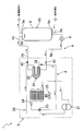
- the heat pump type water heater 1 of this embodiment includes a heat pump unit 2, a hot water storage tank 5, a circulation pump 6, a three-way valve (valve mechanism) 7, and a control unit 10 (see FIG. 2). And.
- a hot water supply terminal A and a water supply source B are connected to the hot water storage tank 5.
- the heat pump type hot water heater 1 performs a boiling operation for heating (boiling) hot water stored in the hot water storage tank 5 and a hot water supply operation for supplying the hot water in the hot water storage tank 5 to the hot water supply terminal A.
- hot water is supplied from the hot water storage tank 5 to the hot water supply terminal A, and water is also supplied from the water supply source B to the hot water storage tank 5.
- hot water is taken out from the hot water storage tank 5, the hot water taken out is heated by the condenser 22 of the heat pump unit 2, and then returned to the hot water storage tank 5.
- a target boiling temperature for example, 65 ° C.
- a target boiling temperature of hot water stored in the hot water storage tank 5 is set by a remote controller (not shown).
- the heat pump unit 2 has a refrigerant circuit 3 in which the refrigerant circulates.
- the refrigerant circuit 3 is provided with a compressor 21, a condenser 22, an expansion valve 23, and an evaporator 24 in this order.
- a fan 25 is disposed in the vicinity of the evaporator 24.
- a refrigerant condensed (liquefied) by the condenser 22 such as an R410A refrigerant, an R143a refrigerant, or an R32 refrigerant is used.
- this refrigerant circuit 3 by starting the compressor 21, low-pressure gas refrigerant is sucked into the compressor 21, and is compressed by the compressor 21 to become high-temperature and high-pressure gas refrigerant. Thereafter, the high-temperature and high-pressure gas refrigerant is cooled and condensed in the condenser 22 by exchanging heat with the hot water sent from the hot water storage tank 5. The condensed refrigerant is decompressed by the expansion valve 23 and then heated and evaporated by heat exchange with air in the evaporator 24, and again returns to the compressor 21 as a low-pressure gas refrigerant.
- An intermediate temperature sensor 31 for detecting the temperature of the refrigerant is attached to an intermediate portion of the refrigerant pipe of the condenser 22.
- An outlet temperature sensor 32 for detecting the temperature of the refrigerant that has passed through the condenser 22 is attached near the outlet of the condenser 22 in the refrigerant circuit 3.
- the heat pump unit 2 has an outside air temperature sensor 33. The outside air temperature sensor 33 detects the temperature of the air sucked into the evaporator 24.
- the hot water storage tank 5 and the condenser 22 of the heat pump unit 2 are connected by a hot water circuit 4.
- a first return port 5a, a discharge port 5b, and a water supply port 5c are provided.
- a second return port 5d and a hot water outlet 5e are provided. Is provided.
- the return branch pipe 4c is connected to the first return port 5a, and the return branch pipe 4d is connected to the second return port 5d.
- the return branch pipes 4 c and 4 d constitute a part of the hot water circuit 4.
- the return branch pipes 4 c and 4 d are connected to the return pipe 4 b via the three-way valve 7.
- the return pipe 4 b is connected to the condenser 22.
- the three-way valve 7 switches between a first state in which the return pipe 4b and the return branch pipe 4c are connected and a second state in which the return pipe 4b and the return branch pipe 4d are connected.
- first state hot water heated by the condenser 22 is supplied to the hot water storage tank 5 via the first return port 5a, and when the three-way valve 7 is in the second state, condensation is performed.
- Hot water heated by the vessel 22 is supplied to the hot water storage tank 5 through the second return port 5d.
- the return pipe 4b is provided with a tapping temperature sensor 42 for detecting the temperature of the hot water that has passed through the condenser 22.
- the outgoing pipe 4a leading to the condenser 22 is connected to the discharge port 5b.
- the forward piping 4 a constitutes a part of the hot water circuit 4.
- the outgoing pipe 4a is provided with a circulation pump 6 and an incoming water temperature sensor 41 for detecting the temperature of hot water flowing into the condenser 22 (hereinafter referred to as incoming water temperature).
- the circulation pump 6 is provided to circulate the hot water in the hot water circuit 4 during the boiling operation and to adjust the flow rate of the hot water supplied to the hot water storage tank 5.
- hot water including the case of water
- hot water storage tank 5 is drawn into the outgoing pipe 4 a from the outlet 5 b and heated in the condenser 22, and then the first return port 5 a or the first It is returned to the hot water storage tank 5 through the two return ports 5d.
- the flow rate of the hot water supplied to the hot water storage tank 5 increases, and when the rotational speed of the circulation pump 6 is decreased, the flow rate decreases.
- the water supply port 5c is connected to the water supply source B, and the hot water outlet 5e is connected to the hot water supply terminal A. During the hot water supply operation, hot hot water flows out of the hot water outlet 5e of the hot water storage tank 5, and low temperature water flows in from the hot water supply port 5c of the hot water storage tank 5.
- a tank temperature sensor 43 is attached to the outer surface of the hot water storage tank 5.
- the tank temperature sensor 43 is for detecting the temperature of hot water in the hot water storage tank 5.
- the tank temperature sensor 43 is installed at a substantially intermediate portion in the vertical direction of the hot water storage tank 5.
- hot hot water flows out of the hot water outlet 5e of the hot water storage tank 5 and low temperature water flows in from the hot water supply port 5c of the hot water storage tank 5, so that the hot water of the hot water storage tank 5 is hot at the top side and low at the bottom side.
- region of the low temperature warm water of a bottom part expands upward, so that hot water supply is performed. Therefore, it is possible to detect how much hot water remains in the hot water storage tank 5 based on the temperature detected by the tank temperature sensor 43 (detection of remaining hot water amount).
- the heat pump type water heater 1 of the present embodiment has a circulation boiling mode and a single over-boiling mode as operation modes of the boiling operation.
- the circulation boiling mode and the overheating mode are switched based on the temperature of the warm water supplied from the hot water storage tank 5 to the condenser 22 (incoming water temperature).
- the circulation boiling mode is a mode in which the three-way valve 7 is set to the first state and hot water heated by the condenser 22 is supplied to the bottom side of the hot water storage tank 5 through the first return port 5a.
- the flow rate supplied to the hot water storage tank 5 in the circulating boiling mode is the first flow rate that is a relatively large constant value. Further, by supplying hot hot water to the bottom side of the hot water storage tank 5, convection due to a temperature difference occurs in the hot water storage tank 5, so the hot water in the hot water storage tank 5 is agitated. Almost uniform. Therefore, by continuously performing the circulating boiling mode operation, the temperature of the hot water in the entire hot water storage tank 5 gradually increases.
- the one over-boiling up mode is a mode in which the three-way valve 7 is in the second state and hot water having a flow rate smaller than the first flow rate is supplied to the top side of the hot water storage tank 5.
- the flow rate supplied to the hot water storage tank 5 in the single overheating mode is a second flow rate that is smaller than the first flow rate, and is changed based on the target boiling temperature, and is stirred in the hot water storage tank 5. This is a flow rate that hardly generates any of the above.
- high temperature hot water is supplied to the top side of the hot water storage tank 5 so that stirring does not occur.
- the region of high-temperature hot water expands from the side toward the bottom.
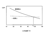
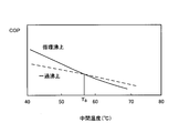
- FIG. 3 is an example of a graph showing the relationship between the incoming water temperature and the COP.
- COP Coefficient Of Performance
- COP is a value representing the heating capacity per 1 kW of power consumption, and is an index indicating energy consumption efficiency. The larger the COP, the higher the energy consumption efficiency.
- FIG. 3 corresponds to the condition where the R410A refrigerant is used and the outside air temperature is Ta.
- the COP decreases as the incoming water temperature increases.
- the single boiling mode has a slower decrease than the circulating boiling mode.
- circulation and cross the heating-up mode of the curve and transient heating-up mode curve when the incoming water temperature is lower than the threshold value T A is circulating the heating-up mode COP is higher than the transient heating-up mode , when the incoming water temperature is higher than the threshold value T a is, COP is higher than the transient heating-up mode is circulating heating-up mode.
- the heating-up operation When the heating-up operation is started, since the incoming water temperature is lower than the threshold value T A, and operated in a cyclic heating-up mode, then the incoming water temperature by the heating-up operation is performed is higher than the threshold value T A When this happens, the operation can be performed in the mode with the higher COP by switching to the operation in the overheating mode.
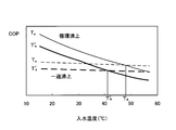
- FIG. 4 shows how the relationship between the incoming water temperature and the COP changes when the outside air temperature decreases from Ta to Ta ′ (where Ta ′ ⁇ Ta) under the conditions shown in FIG.
- the COP decreases as the outside air temperature decreases in both the circulating boiling mode and the overheating mode. Therefore, the threshold value T A of the incoming water temperature at which the magnitude of the COP in the circulating boiling mode and the one-over boiling mode is switched decreases to T A ′ as the outside air temperature decreases.
- heat pump water heater 1 of the present embodiment when the outside air temperature is Ta, based on a threshold T A of the incoming water temperature when a magnitude of the COP of the circulating heating-up mode and the transient heating-up mode is interchanged, circulation boiling It is possible to switch between the upper mode and the one-boiling upper mode.
- the incoming water temperature detected by the incoming water temperature sensor 41 is smaller than the threshold value T A performs the heating-up operation in the circulation boiling on mode, when the incoming water temperature is above the threshold value T A is a transient heating-up mode Perform boiling operation.
- the boiling operation is performed only in the circulating boiling mode, or the boiling operation is performed only in the single overheating mode.
- COP can be improved.
- the threshold value T A of the incoming water temperature interchanged large and small COP circulation boiling on mode and transient heating-up mode since it varies depending on the outside air temperature, heat pump of this embodiment in water heater 1, the threshold value T a of the incoming water temperature to switch modes, is changed according to the outside air temperature. Specifically, the threshold T A is the ambient air temperature is changed lower the lower.
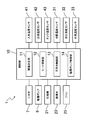
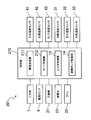
- the control unit 10 includes a threshold value determination unit 11, a mode switching unit 12, a three-way valve control unit 13, and a circulation pump control unit 14.
- Threshold value determining unit 11 based on the outside air temperature detected by the outside air temperature sensor 33, to determine the threshold value T A of the incoming water temperature.
- Threshold value determining unit 11 stores a plurality of so as to correspond to each of the outside air temperature, the threshold T A of the incoming water temperature the magnitude of the COP of the COP and transient heating-up mode of circulating the heating-up mode is interchanged.
- the threshold determination unit 11 from among a plurality of thresholds T A stored, selects and determines the threshold value T A corresponding to the outside air temperature.
- Mode switching part 12 when the heating-up operation, the incoming water temperature detected by the incoming water temperature sensor 41, based on a threshold T A that is determined by the threshold value determining unit 11, and a circulation heating-up mode and the transient heating-up mode Switch. If the incoming water temperature is less than the threshold value T A is switched to the circulation boiling on mode, when the incoming water temperature is above the threshold value T A is switched to transient heating-up mode.
- the three-way valve control unit 13 switches the three-way valve 7 during the boiling operation according to the mode determined by the mode switching unit 12. In the case of the circulation boiling mode, the three-way valve 7 is switched to the first state, and in the case of the one-over boiling mode, the three-way valve 7 is switched to the second state.
- the circulation pump control unit 14 controls the rotation speed of the circulation pump 6 during the boiling operation according to the mode determined by the mode switching unit 12.
- the rotation speed of the circulation pump 6 is controlled so that the flow rate of the hot water supplied to the hot water storage tank 5 becomes the first flow rate set in advance.
- the rotational speed of the circulation pump 6 is controlled based on the temperature difference between the incoming water temperature and the boiling target temperature. As the temperature difference between the incoming water temperature and the boiling target temperature increases, the rotational speed of the circulation pump 6 decreases.
- the circulation pump control unit 14 has a flow rate of hot water supplied to the hot water storage tank 5 that is smaller than the first flow rate and hardly causes stirring in the hot water storage tank 5 as described above.
- the rotational speed of the circulation pump 6 is controlled within a range not exceeding the second flow rate that is the flow rate.
- the mode is switched to either the circulation boiling mode or the single overheating mode based on the incoming water temperature supplied to the condenser 22. Therefore, even if the COP in the circulating boiling mode and the COP in the one-over boiling mode are switched depending on the size of the incoming water temperature, the operation of the heat pump water heater is performed by operating in the higher COP mode. Energy consumption efficiency can be improved.
- incoming water temperature supplied to the condenser 22 is lower than the threshold value T A is, COP is operated at high circulating heating-up mode of the circulating heating-up mode and the transient heating-up mode, the condenser when the incoming water temperature supplied to 22 is not less than the threshold value T a is for driving the COP at a high transient heating-up mode of the circulating heating-up mode and the transient heating-up mode, it is possible to improve the efficiency .
- the COP changes in both the circulating boiling up mode and the single overheating mode depending on the outside air temperature (the intake air temperature in the evaporator 24), but the threshold value T A for switching the mode is set in accordance with the outside air temperature. By changing, COP can be further improved.
- the hot water in the hot water storage tank 5 is agitated by natural convection (convection due to temperature difference) by supplying a relatively large flow of heated hot water from the bottom side of the hot water storage tank 5.
- stirring can be prevented.
- the temperature of warm water can be brought close to the boiling target temperature.
- the heat pump type hot water heater 101 of the present embodiment is configured to switch between the circulation boiling mode and the single overheating mode based on the refrigerant temperature (hereinafter referred to as intermediate temperature) in the intermediate part of the refrigerant pipe of the condenser 22.
- intermediate temperature the refrigerant temperature
- Other configurations are the same as those in the first embodiment.
- Components having the same configuration as in the first embodiment are denoted by the same reference numerals and description thereof is omitted as appropriate.
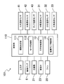
- the control unit 110 of the heat pump type water heater 101 of the present embodiment includes a threshold value determination unit 111, a mode switching unit 112, a three-way valve control unit 13, and a circulation pump control unit 14.
- FIG. 6 is an example of a graph showing the relationship between the intermediate temperature and the COP.
- the curve of the circulation boiling mode intersects with the curve of the overheating mode, and when the intermediate temperature is smaller than the threshold value T B , the circulation heating mode is changed to the overheating mode.
- the COP is higher and the intermediate temperature is equal to or higher than the threshold value T B , the COP is higher in the one-over boiling mode than in the circulating boiling mode.
- a circulation boiling on mode and transient boiling on mode Can be switched.
- T B intermediate temperature which magnitude is interchanged the COP of the circulating heating-up mode and the transient heating-up mode
- a circulation boiling on mode and transient boiling on mode Can be switched.
- Threshold determination unit 111 based on the outside air temperature detected by the outside air temperature sensor 33, to determine the threshold value T B for intermediate temperature.
- the threshold value determination unit 111 is configured to change the intermediate temperature threshold value T at which the COP in the circulating boiling-up mode and the COP in the one-boiling-up mode are switched so as to correspond to each of the plurality of outside air temperatures. I remember B.
- the threshold value determination unit 111 from the stored plurality of threshold values T B, selects and determines the threshold value T B corresponding to outside air temperature.
- Mode switching section 112 during the heating-up operation, an intermediate temperature detected by the intermediate temperature sensor 31, based on a threshold T B which is determined by the threshold determination unit 111, a circulation boiling on mode and transient heating-up mode Switch.
- a threshold T B which is determined by the threshold determination unit 111
- the mode is switched to the circulating boiling mode
- the mode is switched to the one overheating mode.
- the mode is switched to either the circulation boiling mode or the single overheating mode based on the intermediate temperature of the condenser 22. Therefore, even when the COP in the circulating boiling mode and the COP in the one-over boiling mode are switched depending on the size of the intermediate temperature, by operating in the mode with the higher COP, Energy consumption efficiency can be improved.
- the heat pump type water heater 201 of the present embodiment is configured to switch between the circulation boiling mode and the overheating mode based on the refrigerant temperature at the outlet portion of the refrigerant pipe of the condenser 22 (hereinafter referred to as outlet temperature).
- outlet temperature the refrigerant temperature at the outlet portion of the refrigerant pipe of the condenser 22
- Other configurations are the same as those in the first embodiment. Components having the same configuration as in the first embodiment are denoted by the same reference numerals and description thereof is omitted as appropriate.
- control unit 210 of the heat pump type water heater 201 of this embodiment includes a threshold value determination unit 211, a mode switching unit 212, a three-way valve control unit 13, and a circulation pump control unit 14.
- FIG. 8 is an example of a graph showing the relationship between the outlet temperature and the COP. As shown in FIG. 8, the curve of the cyclic boiling mode intersects with the curve of the single boiling point mode, and when the outlet temperature is lower than the threshold value T C , the single boiling point mode is the cyclic boiling mode. When the COP is higher and the outlet temperature is equal to or higher than the threshold value T C , the circulating boiling mode is higher than the one-over boiling mode.
- the circulation boiling mode and the overheating mode are based on the outlet temperature threshold T C where the size of the COP in the circulation boiling mode and the overheating mode is switched. Can be switched.
- T C the threshold value
- the boiling operation is performed in the one over boiling mode
- the outlet temperature is equal to or higher than the threshold value T C
- the boiling is performed in the circulating boiling mode.
- T C the threshold value
- the top drive In this way, by switching between the circulating boiling mode and the single overheating mode according to the outlet temperature, the boiling operation is performed only in the circulating boiling mode or the boiling operation is performed only in the single overheating mode. Compared with the case, COP can be improved.
- the threshold determination unit 211 determines a threshold T C for the outlet temperature based on the outside air temperature detected by the outside temperature sensor 33. Similarly to the first embodiment, the threshold value determination unit 211 is configured to change the size of the COP in the circulating boiling-up mode and the COP in the one-overheating mode so as to correspond to each of the plurality of outside air temperatures. I remember C. Thus, the threshold value determination unit 211, from the stored plurality of threshold values T C, determined by selecting the threshold T C corresponding to outside air temperature.
- the mode switching unit 212 switches between the circulating boiling mode and the overheating mode based on the outlet temperature detected by the outlet temperature sensor 32 and the threshold value T C determined by the threshold value determining unit 211 during the boiling operation. Switch. When the outlet temperature is lower than the threshold value T C , the mode is switched to the circulation boiling mode, and when the outlet temperature is equal to or higher than the threshold value T B , the mode is switched to the one overheating mode.
- the mode is switched to either the circulation boiling mode or the single overheating mode based on the outlet temperature of the condenser 22. Therefore, even when the COP in the circulating boiling mode and the COP in the one-over boiling mode are switched depending on the size of the intermediate temperature, by operating in the mode with the higher COP, Energy consumption efficiency can be improved.
- the heat pump type water heater 301 of the present embodiment is based on the difference between the refrigerant temperature in the vicinity of the outlet of the condenser 22 and the refrigerant temperature in the intermediate part of the refrigerant pipe of the condenser 22 (hereinafter referred to as intermediate / outlet temperature difference). It is different from the first embodiment in that it switches between the circulating boiling mode and the overheating mode. Other configurations are the same as those in the first embodiment. Components having the same configuration as in the first embodiment are denoted by the same reference numerals and description thereof is omitted as appropriate.
- control unit 310 of the heat pump type water heater 301 of the present embodiment includes a threshold value determination unit 311, a mode switching unit 312, a three-way valve control unit 13, and a circulation pump control unit 14.
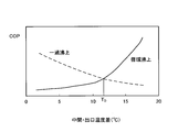
- FIG. 10 is an example of a graph showing the relationship between the intermediate / outlet temperature and the COP.
- the curve of the cyclic boiling mode intersects with the curve of the single overheating mode, and when the intermediate / outlet temperature is smaller than the threshold value T D , the single boiling mode is set to the cyclic boiling mode.
- the COP is higher than that in the upper mode and the intermediate / outlet temperature is equal to or higher than the threshold value T D
- the circulating boiling mode is higher than the one-over boiling mode.
- the circulating boiling mode and the overheating mode are based on the threshold value T D of the intermediate / exit temperature at which the size of the COP in the circulating boiling mode and the overheating mode is switched. And are switched.
- An intermediate temperature detected by the intermediate temperature sensor 31, when the intermediate outlet temperature difference is the temperature difference between the outlet temperature detected by the outlet temperature sensor 32 is the threshold value T D is smaller than the heating-up transient heating-up mode It performs the operation, if the intermediate outlet temperature difference is the threshold value T D above, performs the heating-up operation in a cyclic heating-up mode.
- Threshold determination unit 31 determines the threshold T D of the intermediate outlet temperature difference.
- the threshold value determination unit 311 is configured to detect an intermediate outlet temperature difference in which the size of the COP in the circulating boiling-up mode and the COP in the one-over boiling mode is switched so as to correspond to each of the plurality of outside air temperatures. stores threshold T D.
- the threshold value determination unit 311 from among a plurality of thresholds T D stored, selects and determines the threshold value T D corresponding to the outside air temperature.
- Mode switching section 312 during the heating-up operation, switches and the intermediate outlet temperature difference, based on a threshold T D which has been determined by the threshold determination unit 311, a circulation boiling on mode and transient heating-up mode. If the intermediate outlet temperature difference is smaller than the threshold value T D is switched to transient heating-up mode, when the intermediate outlet temperature difference is more than the threshold T D is switched to the circulation boiling on mode.
- the mode is switched to either the circulation boiling mode or the single overheating mode based on the temperature difference between the intermediate temperature of the condenser 22 and the outlet temperature. Therefore, even if the COP in the circulating boiling mode and the COP in the one-over boiling mode are switched depending on the magnitude of the intermediate outlet temperature difference, the heat pump hot water supply is operated by operating in the higher COP mode. The energy consumption efficiency of the machine can be improved.
- the circulation boiling mode and the single overheating mode are switched based on any one of the incoming water temperature, the intermediate temperature, the outlet temperature, and the intermediate outlet temperature difference. Based on the operation time, the circulation boiling mode and the single overheating mode may be switched. Since this boiling operation time corresponds to changes in the incoming water temperature, intermediate temperature, outlet temperature, and intermediate outlet temperature difference, as in the above embodiment, switching between the circulating boiling mode and the single super-boiling mode It can be performed.
- the flow rate of the hot water supplied to the hot water storage tank 5 is controlled by controlling the number of revolutions of the circulation pump 6, but a flow rate adjusting valve is provided in the forward piping 4a or the return piping 4b.
- the flow rate of the hot water supplied to the hot water storage tank 5 may be controlled by controlling the flow rate adjusting valve.
- the threshold value is changed according to the outside air temperature.
- the mode may be switched using a constant threshold value regardless of the outside air temperature.
- it may be a threshold at which the magnitudes of the COPs in the circulation boiling mode and the one-over boiling mode in the case where the outside air temperature is an average value are switched.
- hot water is supplied to the bottom side of the hot water storage tank 6, but hot water may be supplied to the top side of the hot water storage tank 6.
- the hot water is supplied to the top side of the hot water storage tank 6 in both the circulating boiling mode and the one-over boiling mode, so that the three-way valve 7 is controlled. There is no need. Therefore, the three-way valve 7 and the return branch pipe 4c need not be provided.
- an agitation preventing member is disposed in the hot water storage tank 6 of this modified form so as to face the second return port 5d. Therefore, the hot water in the hot water storage tank 6 can be prevented from being stirred by the hot water supplied from the second return port 5d.
- the flow rate (first flow rate) of hot water supplied to the bottom side of the hot water storage tank 6 is always the same value, but is changed based on the boiling target temperature and the incoming water temperature. Also good.
- coolant which is not condensed with other condensers, such as R134A, R407C, for example.
- the circulation boiling mode and the single overheating mode are switched based on any of the incoming water temperature, the intermediate temperature, the outlet temperature, and the intermediate outlet temperature difference.
- the circulation boiling mode and the overheating mode may be switched based on the refrigerant temperature in the other part or the hot water temperature in the other part of the hot water circuit connecting the condenser and the hot water storage tank.
Landscapes
- Engineering & Computer Science (AREA)
- Physics & Mathematics (AREA)
- Thermal Sciences (AREA)
- Chemical & Material Sciences (AREA)
- Combustion & Propulsion (AREA)
- Mechanical Engineering (AREA)
- General Engineering & Computer Science (AREA)
- Heat-Pump Type And Storage Water Heaters (AREA)
Abstract
L'objectif de cette invention est un rendement énergétique amélioré. Ce chauffe-eau du type pompe à chaleur (1) est doté d'une unité de pompe à chaleur (2) possédant un circuit pour fluide frigorigène (3) dans lequel circule un fluide frigorigène comprimé dans un condenseur (22), et d'un réservoir de stockage d'eau chaude (5) destiné à stocker l'eau chaude chauffée dans le condenseur (22). Ce chauffe-eau du type pompe à chaleur permet d'adopter un module ébullition de circulation dans lequel une première quantité d'écoulement d'eau chauffée est apportée jusqu'au réservoir de stockage d'eau chaude, et un mode ébullition de transition dans lequel une seconde quantité d'écoulement d'eau chauffée supérieure à la première quantité d'écoulement est apportée jusqu'au côté supérieur du réservoir de stockage d'eau chaude (5), et ledit chauffe-eau du type pompe à chaleur alterne entre le mode ébullition de circulation et le mode ébullition de transition sur la base de la température du fluide frigorigène apporté au condenseur (22).
Priority Applications (3)
| Application Number | Priority Date | Filing Date | Title |
|---|---|---|---|
| CN201280012417.9A CN103415747B (zh) | 2011-03-10 | 2012-03-09 | 热泵式热水器 |
| EP12755362.6A EP2685177B1 (fr) | 2011-03-10 | 2012-03-09 | Chauffe-eau du type pompe à chaleur |
| JP2013503627A JPWO2012121382A1 (ja) | 2011-03-10 | 2012-03-09 | ヒートポンプ式給湯機 |
Applications Claiming Priority (2)
| Application Number | Priority Date | Filing Date | Title |
|---|---|---|---|
| JP2011052445 | 2011-03-10 | ||
| JP2011-052445 | 2011-03-10 |
Publications (1)
| Publication Number | Publication Date |
|---|---|
| WO2012121382A1 true WO2012121382A1 (fr) | 2012-09-13 |
Family
ID=46798333
Family Applications (1)
| Application Number | Title | Priority Date | Filing Date |
|---|---|---|---|
| PCT/JP2012/056161 Ceased WO2012121382A1 (fr) | 2011-03-10 | 2012-03-09 | Chauffe-eau du type pompe à chaleur |
Country Status (4)
| Country | Link |
|---|---|
| EP (1) | EP2685177B1 (fr) |
| JP (1) | JPWO2012121382A1 (fr) |
| CN (1) | CN103415747B (fr) |
| WO (1) | WO2012121382A1 (fr) |
Cited By (5)
| Publication number | Priority date | Publication date | Assignee | Title |
|---|---|---|---|---|
| CN103900253A (zh) * | 2012-12-25 | 2014-07-02 | 福州斯狄渢电热水器有限公司 | 即开即用式空气能热泵热水器及其控制方法 |
| JP2015224796A (ja) * | 2014-05-26 | 2015-12-14 | 三菱電機株式会社 | 給湯装置 |
| WO2018003628A1 (fr) * | 2016-06-27 | 2018-01-04 | ダイキン工業株式会社 | Système d'alimentation en eau chaude |
| WO2019016845A1 (fr) * | 2017-07-18 | 2019-01-24 | 三菱電機株式会社 | Dispositif d'alimentation en eau chaude |
| US20190219303A1 (en) * | 2015-08-12 | 2019-07-18 | Anthony Michael SARKIS, SR. | Hot water heating systems and related methods |
Families Citing this family (2)
| Publication number | Priority date | Publication date | Assignee | Title |
|---|---|---|---|---|
| FR3046218B1 (fr) * | 2015-12-23 | 2019-06-07 | Atlantic Industrie | Procede de regulation d'un chauffe-eau et chauffe-eau associe |
| CN111928478B (zh) * | 2020-08-10 | 2021-10-12 | 中山市帕科电器科技有限公司 | 一种可增加热水内循环效率的热水器 |
Citations (3)
| Publication number | Priority date | Publication date | Assignee | Title |
|---|---|---|---|---|
| JP2002228258A (ja) | 2001-02-06 | 2002-08-14 | Toshiba Kyaria Kk | ヒートポンプ給湯器 |
| JP2005172251A (ja) * | 2003-12-08 | 2005-06-30 | Sanyo Electric Co Ltd | ヒートポンプ式給湯装置 |
| JP2006125654A (ja) * | 2004-10-26 | 2006-05-18 | Matsushita Electric Ind Co Ltd | ヒートポンプ給湯機 |
Family Cites Families (9)
| Publication number | Priority date | Publication date | Assignee | Title |
|---|---|---|---|---|
| JP3737381B2 (ja) * | 2000-06-05 | 2006-01-18 | 株式会社デンソー | 給湯装置 |
| JP2003106653A (ja) * | 2001-09-28 | 2003-04-09 | Kansai Electric Power Co Inc:The | ヒートポンプ式給湯装置 |
| JP3849518B2 (ja) * | 2001-12-14 | 2006-11-22 | 株式会社デンソー | ヒートポンプ式給湯装置 |
| CN201007558Y (zh) * | 2007-01-27 | 2008-01-16 | 苏权兴 | 热泵热水器 |
| JP2007139415A (ja) * | 2007-02-09 | 2007-06-07 | Denso Corp | ヒートポンプ式給湯器 |
| WO2009069734A1 (fr) * | 2007-11-30 | 2009-06-04 | Daikin Industries, Ltd. | Appareil d'alimentation en eau chaude |
| JP5181828B2 (ja) * | 2008-05-21 | 2013-04-10 | パナソニック株式会社 | ヒートポンプ給湯機 |
| DE102009017423B4 (de) * | 2009-04-15 | 2020-10-08 | Stiebel Eltron Gmbh & Co. Kg | Verfahren zur Ladungssteuerung eines Warmwasserschichtspeichers mit einer Wärmepumpe |
| CN201637107U (zh) * | 2010-02-05 | 2010-11-17 | 广东美的电器股份有限公司 | 带水箱的热泵热水机 |
-
2012
- 2012-03-09 JP JP2013503627A patent/JPWO2012121382A1/ja active Pending
- 2012-03-09 EP EP12755362.6A patent/EP2685177B1/fr active Active
- 2012-03-09 WO PCT/JP2012/056161 patent/WO2012121382A1/fr not_active Ceased
- 2012-03-09 CN CN201280012417.9A patent/CN103415747B/zh active Active
Patent Citations (3)
| Publication number | Priority date | Publication date | Assignee | Title |
|---|---|---|---|---|
| JP2002228258A (ja) | 2001-02-06 | 2002-08-14 | Toshiba Kyaria Kk | ヒートポンプ給湯器 |
| JP2005172251A (ja) * | 2003-12-08 | 2005-06-30 | Sanyo Electric Co Ltd | ヒートポンプ式給湯装置 |
| JP2006125654A (ja) * | 2004-10-26 | 2006-05-18 | Matsushita Electric Ind Co Ltd | ヒートポンプ給湯機 |
Non-Patent Citations (1)
| Title |
|---|
| See also references of EP2685177A4 |
Cited By (9)
| Publication number | Priority date | Publication date | Assignee | Title |
|---|---|---|---|---|
| CN103900253A (zh) * | 2012-12-25 | 2014-07-02 | 福州斯狄渢电热水器有限公司 | 即开即用式空气能热泵热水器及其控制方法 |
| CN103900253B (zh) * | 2012-12-25 | 2017-04-05 | 福州斯狄渢电热水器有限公司 | 即开即用式空气能热泵热水器及其控制方法 |
| JP2015224796A (ja) * | 2014-05-26 | 2015-12-14 | 三菱電機株式会社 | 給湯装置 |
| US20190219303A1 (en) * | 2015-08-12 | 2019-07-18 | Anthony Michael SARKIS, SR. | Hot water heating systems and related methods |
| US11105533B2 (en) * | 2015-08-12 | 2021-08-31 | Anthony Michael SARKIS, SR. | Hot water heating systems and related methods |
| WO2018003628A1 (fr) * | 2016-06-27 | 2018-01-04 | ダイキン工業株式会社 | Système d'alimentation en eau chaude |
| JP2018004094A (ja) * | 2016-06-27 | 2018-01-11 | ダイキン工業株式会社 | 給湯システム |
| WO2019016845A1 (fr) * | 2017-07-18 | 2019-01-24 | 三菱電機株式会社 | Dispositif d'alimentation en eau chaude |
| JPWO2019016845A1 (ja) * | 2017-07-18 | 2020-02-06 | 三菱電機株式会社 | 給湯装置 |
Also Published As
| Publication number | Publication date |
|---|---|
| EP2685177A4 (fr) | 2014-08-20 |
| EP2685177B1 (fr) | 2016-05-04 |
| JPWO2012121382A1 (ja) | 2014-07-17 |
| CN103415747B (zh) | 2016-03-02 |
| CN103415747A (zh) | 2013-11-27 |
| EP2685177A1 (fr) | 2014-01-15 |
Similar Documents
| Publication | Publication Date | Title |
|---|---|---|
| WO2012121382A1 (fr) | Chauffe-eau du type pompe à chaleur | |
| JP5524571B2 (ja) | ヒートポンプ装置 | |
| KR102189464B1 (ko) | 난방 시스템 | |
| JP4698697B2 (ja) | ヒートポンプ給湯機 | |
| WO2011064840A1 (fr) | Dispositif de commande d'appareil de chauffage auxiliaire, système utilisant un fluide chauffé et procédé de commande de l'appareil de chauffage auxiliaire | |
| JP5982839B2 (ja) | ヒートポンプサイクル装置 | |
| JP3915770B2 (ja) | ヒートポンプ給湯機 | |
| JP3659197B2 (ja) | ヒートポンプ給湯機 | |
| JP2012032091A (ja) | ヒートポンプサイクル装置 | |
| JP5014365B2 (ja) | ヒートポンプ給湯機 | |
| JP3700474B2 (ja) | ヒートポンプ給湯機 | |
| JP6982272B2 (ja) | ヒートポンプ式給湯装置 | |
| JP5478403B2 (ja) | ヒートポンプ給湯装置 | |
| JP6716333B2 (ja) | 給湯システム | |
| JP2008224067A (ja) | ヒートポンプ給湯装置 | |
| JP3703995B2 (ja) | ヒートポンプ給湯機 | |
| JP2010133598A (ja) | ヒートポンプ式給湯機 | |
| JP6137016B2 (ja) | ヒートポンプ式給湯機、およびヒートポンプ式給湯機の制御方法 | |
| JP3856025B2 (ja) | ヒートポンプ給湯機 | |
| JP5761016B2 (ja) | ヒートポンプ式給湯機 | |
| JP5312444B2 (ja) | ヒートポンプ給湯機 | |
| JP3900186B2 (ja) | ヒートポンプ給湯機 | |
| JP4334153B2 (ja) | ヒートポンプ式給湯器 | |
| JP2009085476A (ja) | ヒートポンプ給湯装置 | |
| JP4449779B2 (ja) | ヒートポンプ給湯機 |
Legal Events
| Date | Code | Title | Description |
|---|---|---|---|
| 121 | Ep: the epo has been informed by wipo that ep was designated in this application |
Ref document number: 12755362 Country of ref document: EP Kind code of ref document: A1 |
|
| ENP | Entry into the national phase |
Ref document number: 2013503627 Country of ref document: JP Kind code of ref document: A |
|
| NENP | Non-entry into the national phase |
Ref country code: DE |
|
| WWE | Wipo information: entry into national phase |
Ref document number: 2012755362 Country of ref document: EP |