WO2012123993A1 - Émetteur pour détecter un corps mobile dans une canalisation, corps mobile circulant dans une canalisation et système pour détecter un corps mobile circulant dans une canalisation - Google Patents
Émetteur pour détecter un corps mobile dans une canalisation, corps mobile circulant dans une canalisation et système pour détecter un corps mobile circulant dans une canalisation Download PDFInfo
- Publication number
- WO2012123993A1 WO2012123993A1 PCT/JP2011/001586 JP2011001586W WO2012123993A1 WO 2012123993 A1 WO2012123993 A1 WO 2012123993A1 JP 2011001586 W JP2011001586 W JP 2011001586W WO 2012123993 A1 WO2012123993 A1 WO 2012123993A1
- Authority
- WO
- WIPO (PCT)
- Prior art keywords
- magnetic field
- transmitter
- permanent magnet
- pipe
- moving body
- Prior art date
- Legal status (The legal status is an assumption and is not a legal conclusion. Google has not performed a legal analysis and makes no representation as to the accuracy of the status listed.)
- Ceased
Links
Images


Classifications
-
- G—PHYSICS
- G01—MEASURING; TESTING
- G01B—MEASURING LENGTH, THICKNESS OR SIMILAR LINEAR DIMENSIONS; MEASURING ANGLES; MEASURING AREAS; MEASURING IRREGULARITIES OF SURFACES OR CONTOURS
- G01B7/00—Measuring arrangements characterised by the use of electric or magnetic techniques
- G01B7/003—Measuring arrangements characterised by the use of electric or magnetic techniques for measuring position, not involving coordinate determination
-
- F—MECHANICAL ENGINEERING; LIGHTING; HEATING; WEAPONS; BLASTING
- F16—ENGINEERING ELEMENTS AND UNITS; GENERAL MEASURES FOR PRODUCING AND MAINTAINING EFFECTIVE FUNCTIONING OF MACHINES OR INSTALLATIONS; THERMAL INSULATION IN GENERAL
- F16L—PIPES; JOINTS OR FITTINGS FOR PIPES; SUPPORTS FOR PIPES, CABLES OR PROTECTIVE TUBING; MEANS FOR THERMAL INSULATION IN GENERAL
- F16L55/00—Devices or appurtenances for use in, or in connection with, pipes or pipe systems
- F16L55/26—Pigs or moles, i.e. devices movable in a pipe or conduit with or without self-contained propulsion means
- F16L55/48—Indicating the position of the pig or mole in the pipe or conduit
-
- G—PHYSICS
- G01—MEASURING; TESTING
- G01V—GEOPHYSICS; GRAVITATIONAL MEASUREMENTS; DETECTING MASSES OR OBJECTS; TAGS
- G01V3/00—Electric or magnetic prospecting or detecting; Measuring magnetic field characteristics of the earth, e.g. declination, deviation
- G01V3/15—Electric or magnetic prospecting or detecting; Measuring magnetic field characteristics of the earth, e.g. declination, deviation specially adapted for use during transport, e.g. by a person, vehicle or boat
Definitions
- the present invention relates to a transmitter for detecting an in-pipe moving body mounted on the in-pipe moving body in order to detect the in-pipe moving body that moves inside the pipe and performs cleaning in the pipe from the outside of the pipe.
- the present invention also relates to an in-pipe moving body on which the transmitter is mounted, and an in-pipe moving body detection system that accurately detects the position of the in-pipe moving body based on a rotating magnetic field generated from the transmitter.
- an in-pipe moving body having an outer diameter approximately equal to the inner diameter of the pipe is used. After the in-pipe moving body is inserted into the pipe to be cleaned, a fluid is caused to flow through the pipe, and the in-pipe moving body is moved in the length direction of the pipe by the fluid pressure of the fluid. As a result, the residue in the pipe and the deposit attached to the inner peripheral wall of the pipe are discharged from the outlet of the pipe by the moving body in the pipe.
- Such an in-pipe moving body is called a pig.
- the transmitter in the pipe is equipped with a transmitter.
- the signal from the transmitter is detected by the detector to identify the position of the in-pipe moving body.
- a transmitter that generates a magnetic field for detection is known, and Patent Document 1 discloses an in-pipe moving body including this type of transmitter.
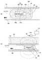
- FIG. 5A and 5 (b) are explanatory views showing a moving body in a tube provided with a conventional transmitter that generates a magnetic field for detection.
- the in-pipe moving body 100 has a bullet shape, and is inserted into the pipe 101 in a state where the tapered side is the front side in the moving direction M0.
- the transmitter 102 includes an iron core 103 and an electromagnetic coil 105 including a coil 104 wound around the iron core 103, a pulse generation circuit 106 for applying a pulse current having a constant period to the electromagnetic coil 105, and a pulse generation circuit 106.
- a battery 107 and a switch 108 for supplying electric power to the electromagnetic coil 105 via the switch are provided.
- the transmitter 102 is mounted on the in-pipe moving body 100 with the center line L0 of the electromagnetic coil 105 along the moving direction M0 of the in-pipe moving body 100.
- the in-pipe moving body 100 moves in the tube 101 while maintaining a posture in which the center line L0 of the electromagnetic coil 105 is parallel to the center axis 101A of the tube 101.
- a magnetic sensor probe 110a is provided when detecting the moving body 100 in the pipe that is stopped in the pipe 101 horizontally buried in the ground several meters away from the ground 109.
- the detected detector 110 is moved along the buried route on the ground.
- the detector 110 detects a magnetic field vector of a magnetic field (two-dot chain line in the figure) periodically generated from the electromagnetic coil 105, and thereby identifies the position of the in-pipe moving body 100.
- the transmitter 102 in the conventional in-pipe moving body is mounted on the in-pipe moving body 100 so that the magnetic pole surface 105a (the end surface of the iron core 103) of the electromagnetic coil 105 faces the moving direction M0 of the in-pipe moving body 100.
- the detector 110 detects the maximum magnetic field from the transmitter 102, the direction of the magnetic field vector V0 coincides with the central axis 101A of the tube 101.
- knowledge and skill regarding the magnetic field line route of the magnetic field generated by the transmitter 102 is required.
- the transmitter 102 is mounted on the in-pipe moving body 100 so that the center line L0 of the electromagnetic coil 105 is along the vertical direction perpendicular to the moving direction M0 of the in-pipe moving body 100, and the magnetic pole surface 105a of the electromagnetic coil 105 is always on the ground side. It is conceivable to keep the state facing. In this way, the direction of the magnetic field from the transmitter 102 faces the radial direction of the tube 101. As a result, the detector 110 can detect a magnetic field vector from the magnetic pole surface 105a of the electromagnetic coil 105 toward the ground, so that the position of the in-pipe moving body 100 can be accurately identified from the outside of the tube 101 based on the direction of the magnetic field vector.
- the magnetic pole surface 105a of the electromagnetic coil 105 mounted on the in-pipe moving body 100 cannot always be directed to the ground side. If the magnetic pole surface 105a of the electromagnetic coil 105 does not face the ground side, the position of the in-pipe moving body 100 cannot be specified accurately.
- An object of the present invention is to propose a transmitter for detecting a moving body in a tube that generates a rotating magnetic field capable of accurately identifying the position of the moving body in the tube from the outside of the tube based on a magnetic field for position detection generated from the transmitter. It is in.
- Another object of the present invention is to propose an in-pipe mobile body equipped with such a new transmitter and an in-pipe mobile body detection system for detecting the position of the in-pipe mobile body.
- the present invention provides a transmission for detecting an in-pipe moving body mounted on the in-pipe moving body in order to detect the position of the in-pipe moving body from the outside of the pipe in which the in-pipe moving body moves.
- a rotating magnetic field generating mechanism for generating the rotating magnetic field that rotates on an orthogonal plane orthogonal to the rotation center line around a rotation center line parallel to the center axis of the tube to which the moving body in the tube moves. It is characterized by having.
- the rotating magnetic field generating mechanism generates a rotating magnetic field of 10 Hz or less. Since the transmission distance of the ultra-low frequency magnetic signal is long, the detection distance of the moving body in the tube can be increased by setting the frequency of the rotating magnetic field to 10 Hz or less. In addition, since the ultra-low frequency magnetic signal is transmitted in any environment such as vacuum, gas, water, underground, and metal, the position of the moving body in the pipe can be detected regardless of the laying environment of the pipe.
- the rotating magnetic field generating mechanism includes a frequency control unit that switches a frequency of the rotating magnetic field. In this way, even when it is difficult to detect a rotating magnetic field having a specific frequency due to a disturbance magnetic field at the place where the pipe is laid, the position of the moving body in the pipe can be specified by detecting a rotating magnetic field having another frequency.
- the rotating magnetic field generating mechanism includes a frequency control unit that continuously changes the frequency of the rotating magnetic field. In this way, even when it is difficult to detect a rotating magnetic field having a specific frequency due to a disturbance magnetic field at the place where the pipe is laid, the position of the moving body in the pipe can be specified by detecting a rotating magnetic field having another frequency.
- the rotating magnetic field generating mechanism includes a permanent magnet and a rotation driving mechanism that rotates the permanent magnet so that the magnetic pole surface of the permanent magnet moves in the circumferential direction around the rotation center line. It is desirable. If it does in this way, the magnetic field from a transmitter can be made strong by using a permanent magnet with strong magnetic force. Compared with the case where a magnetic field is generated by exciting the coil, an increase in power consumption when the magnetic field from the transmitter is strong can be suppressed.
- the rotation drive mechanism is provided with a motor, and the permanent magnet is attached to the rotation shaft of the motor.
- the rotation drive mechanism includes a bearing mechanism for rotatably supporting the permanent magnet and a drive coil for rotating the permanent magnet by excitation. It is desirable.
- the rotating magnetic field generating mechanism includes a second permanent magnet disposed on the outer peripheral side of the permanent magnet, and a second rotation center in which the magnetic pole surface of the second permanent magnet is parallel to the rotation center line. And a second permanent magnet bearing mechanism bearing mechanism that rotatably supports the second permanent magnet so as to move in the circumferential direction around the line. When the permanent magnet rotates, the second permanent magnet It is desirable for the magnet to rotate.
- the rotating magnetic field generating mechanism in order to generate a rotating magnetic field without using a permanent magnet, includes a plurality of electromagnetic coils and an excitation control unit that excites the plurality of electromagnetic coils in a predetermined order,
- the plurality of electromagnetic coils are arranged such that the axis of each electromagnetic coil extends in different directions perpendicular to the rotation center line.
- the present invention is an in-pipe moving body on which a transmitter that generates a rotating magnetic field for position detection is mounted, and the transmitter is a transmitter having the above-described configuration.
- the in-pipe moving body detection system of the present invention detects a rotating magnetic field generated from the transmitter mounted on the in-pipe moving body and the outside of the tube to which the in-pipe moving body moves, and moves in the pipe. And a detector for identifying the position of the body, wherein the transmitter is a transmitter having the above-described configuration.
- the transmitter generates a rotating magnetic field that rotates about a rotation center line parallel to the central axis of the tube and on an orthogonal plane orthogonal to the rotation center line. Since this rotating magnetic field contains a magnetic field vector that goes to the outside of the tube on an orthogonal plane orthogonal to the central axis of the tube, if the magnetic field vector is detected by a detector, the outside of the tube is based on the direction of the magnetic field vector. Therefore, the position of the moving body in the pipe can be accurately identified. Since the rotating magnetic field generated by the transmitter is a magnetic signal including a frequency component, the magnetic field from the transmitter can be distinguished from a disturbance magnetic field such as geomagnetism using the frequency component. That is, since noise due to a disturbance magnetic field can be removed, the magnetic field from the transmitter can be detected with high sensitivity. Further, since noise due to a disturbance magnetic field can be removed, the detection distance of the moving body in the tube can be increased.
- FIG. 1A is an explanatory diagram showing a pig detection system to which the present invention is applied
- FIG. 1B is an explanatory diagram showing a transmitter of the pig detection system.
- a pig (moving body in pipe) 2 for cleaning the inside of the pipe 1 laid on the site of a factory is made of foamed urethane or rubber, and has a bullet shape with a tapered tip.
- a pig 2 having an outer diameter substantially equal to the inner diameter of the tube 1 is prepared, the pig 2 is inserted into the tube 1 from the distal end side, and a fluid flows through the tube 1.
- the pig 2 is pushed by the fluid pressure F1 of the fluid and moves in the axial direction of the tube 1 along the inner peripheral surface of the tube 1. Residue 3 such as adhering matter adhering to the inner wall of the tube 1 is transferred while being scraped off by the pig 2, and is discharged to the outside together with the pig 2 from the outlet (not shown) of the tube 1.
- the transmitter 2 that generates a rotating magnetic field for position detection for detecting the position of the pig 2 is mounted on the pig 2.
- the rotating magnetic field generating mechanism 10 of the transmitter 4 generates a rotating magnetic field that rotates on an orthogonal plane A orthogonal to the central axis 1A of the tube 1.
- the rotating magnetic field from the transmitter 4 is detected by the detector 5 arranged outside the pipe 1, and the position of the pig 2 in the pipe 1 is determined. Identify.
- the transmitter 4 and the detector 5 constitute a pig detection system 6.
- the transmitter 4 includes a sealed case 11 made of a nonmagnetic member and a rotating magnetic field generation mechanism 10 housed in the case 11.
- the rotating magnetic field generating mechanism 10 includes a permanent magnet 12 and a rotation driving mechanism 13 that rotates the permanent magnet 12.
- the rotation drive mechanism 13 includes a motor 131, a frequency control circuit (frequency control unit) 132 that controls the frequency of the rotating magnetic field by driving the motor 131, and a battery that supplies power to the motor 131 via the frequency control circuit 132.
- 133 and a switch 134 are provided.
- the permanent magnet 12 has a cylindrical shape and is magnetized in two poles so that both end faces thereof are the magnetic pole faces 12a.
- the permanent magnet 12 is fixed to the tip of the rotating shaft 131a of the motor 131 at the center in the central axis direction. Further, the permanent magnet 12 is fixed to the rotating shaft 131a so that the central axis thereof is orthogonal to the rotational center line L1 of the rotating shaft 131a. When the motor 131 rotates, the permanent magnet 12 rotates with the magnetic pole surface 12a about the rotation center line L1.
- the transmitter 4 is mounted on the pig 2 so that the rotation center line L1 of the rotating shaft 131a of the motor 131 faces the moving direction M1 of the pig 2.
- the pig 2 moves in the tube 1 while maintaining a posture in which the rotation center line L1 is parallel to the center axis 1A of the tube 1. Therefore, when the motor 131 rotates, the transmitter 4 causes the rotation center line L1 parallel to the center axis 1A of the tube 1 to be centered on the orthogonal plane A perpendicular to the rotation center line L1 (center axis 1A of the tube 1).
- a rotating magnetic field is generated that rotates.
- the frequency control circuit 132 sets the frequency of the rotating magnetic field by controlling the rotation speed of the motor 131.
- the frequency control circuit 132 drives and controls the motor 131 so that the permanent magnet 12 rotates at a rotation speed of 10 rotations / second, and a 10 Hz rotating magnetic field is generated from the transmitter 4.
- the battery 133 is a lithium ion secondary battery, and can be charged from the outside in a contactless manner while the transmitter 4 is mounted on the pig 2.
- the switch 134 can be remotely operated without contact from the outside while being mounted on the pig 2.
- the detector 5 is based on a magnetic field sensor probe 22 having a coil 21 and an induced electromotive force generated in proportion to the strength of the magnetic field when the magnetic field is linked to the coil 21.
- a magnetic field detection circuit 23 that detects the magnetic field, and a display unit 24 that displays the strength of the magnetic field based on the output from the magnetic field detection circuit 23.
- the induced electromotive force generated in the coil 21 is generated when a magnetic field (magnetic flux) passes through the coil 21. Accordingly, the magnetic field sensor probe 22 has directivity, and the direction of the magnetic field sensor probe 22 at the time when the induced electromotive force is generated is configured to indicate the direction of the magnetic field vector of the detected magnetic field.
- the magnetic field detection circuit 23 includes a high-order bandpass filter 231 and a signal amplification circuit 232. Therefore, the detector 5 can remove noise caused by a disturbance magnetic field such as geomagnetism that does not include a frequency component, and can detect a magnetic signal including a frequency component of 10 Hz from the transmitter 4 with high sensitivity.
- a disturbance magnetic field such as geomagnetism that does not include a frequency component
- the rotating magnetic field generated from the transmitter 4 is a rotating magnetic field that rotates on the orthogonal plane A perpendicular to the rotation center line L1 around the rotation center line L1 parallel to the center axis 1A of the tube 1.
- the rotating magnetic field includes a magnetic field vector V ⁇ b> 1 that goes on the orthogonal plane A orthogonal to the central axis 1 ⁇ / b> A of the tube 1 toward the outside of the tube 1. Therefore, if the magnetic field sensor probe 22 is directed to the ground 1a and a magnetic field whose intensity changes at 10 Hz is detected by the detector 5, the magnetic field vector V1 heading from the magnetic pole surface 12a of the permanent magnet 12 of the transmitter 4 to the ground can be detected.
- the position of the pig 2 can be accurately identified from the outside of the tube 1.
- the direction in which the magnetic field sensor probe 22 faces coincides with the direction of the magnetic field vector V ⁇ b> 1 from the magnetic pole surface 12 a of the permanent magnet 12 toward the ground. Therefore, it can be seen that the pig 2 is located in the tube 1 on the extension line of the magnetic field sensor probe 22.
- the rotating magnetic field generated by the transmitter 4 is an extremely low frequency magnetic signal of 10 Hz.
- the detector 5 can detect the rotating magnetic field from the transmitter 4 with high sensitivity without being affected by noise such as a disturbance magnetic field by removing magnetic frequency components other than 10 Hz. Therefore, the position of the pig 2 can be specified with high accuracy, and the detection distance of the pig 2 becomes long.
- the rotating magnetic field generated by the transmitter 4 is an extremely low frequency magnetic signal
- the transmission distance is long. Therefore, the detection distance capable of detecting the pig 2 is long.
- the ultra-low frequency magnetic signal is transmitted in any environment including vacuum, gas, water, underground, and metal, the position of the pig 2 can be detected regardless of the laying environment of the tube 1.
- the magnetic field from the transmitter 4 can be strengthened by using the permanent magnet 12 having a strong magnetic force. Compared with the case where a magnetic field is generated by exciting a coil, an increase in power consumption required when the magnetic field from the transmitter 4 is strong can be suppressed. Further, when the magnetic field from the transmitter 4 is made strong, there is no need to increase the size of the permanent magnet 12, so that the transmitter 4 does not increase in size and become heavy.
- the frequency control circuit 132 can switch the frequency of the rotating magnetic field from the transmitter 4.
- the frequency control circuit 132 selectively switches the frequency of the rotating magnetic field from the transmitter 4 to either the first frequency or the second frequency lower than the first frequency by setting from the outside. Can do. More specifically, the frequency control circuit 132 rotates the motor by selectively switching the rotation speed between a first speed of 10 rotations / second and a second speed of 8 rotations / second slower than the first rotation speed. The frequency of the magnetic field is switched to 10 Hz (first frequency) or 8 Hz (second frequency). In this way, even if it is difficult to detect the magnetic signal of the first frequency due to the disturbance magnetic field at the place where the tube 1 is laid, the position of the pig 2 can be specified by detecting the magnetic signal of the other frequency.
- the frequency control circuit 132 can switch the frequency of the rotating magnetic field from the transmitter 4 between the first frequency and the second frequency lower than the first frequency every time a predetermined time elapses. . Even in this case, even when it is difficult to detect the magnetic signal of one frequency due to the disturbance magnetic field at the place where the tube 1 is laid, the position of the pig 2 can be specified by detecting the magnetic signal of the other frequency.
- the frequency control circuit 132 may continuously change the frequency of the rotating magnetic field from the transmitter 4 between the first frequency and the first frequency. In this way, since the magnetic signal from the transmitter 4 continuously changes, even when it is difficult to detect a magnetic signal of a specific frequency due to a disturbance magnetic field at the place where the tube 1 is laid, And the position of the pig 2 can be specified.
- the frequency control circuit 132 may stop the rotation of the motor 131 every time a predetermined time elapses. In this way, since the consumption of the battery 133 can be suppressed, the time during which the transmitter can operate can be extended. As a result, the operating time for operating the pig 2 can be extended. Further, since the magnetic field is generated from the permanent magnet 12 even when the rotation of the motor 131 is stopped, the magnetic field from the permanent magnet 12 is detected by the detector 5 so that the pig 2 The position can be specified.
- the rotating magnetic field generating mechanism includes the second permanent magnet supported on the outer peripheral side of the permanent magnet 12 so as to be rotatable around the second rotation center line parallel to the rotation center line L1.
- the second permanent magnet may be rotated when the permanent magnet 12 rotates.
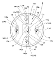
- FIG. 2 is an explanatory diagram of a transmitter according to a modified example in which the rotating magnetic field generating mechanism includes the second permanent magnet, and the inside of the pig 2 is viewed from the direction of the rotation center line L1.
- the rotating magnetic field generation mechanism 10A includes four permanent magnets 141 to 144 arranged at equal angular intervals around the rotation center line L1 as the second permanent magnet 14.
- the permanent magnets 141 to 144 are two-pole magnetized so that both end surfaces thereof are the magnetic pole surfaces 141a to 144a, and are arranged at positions overlapping when viewed from a direction orthogonal to the rotation center line L1.
- the permanent magnets 141 to 144 are rotated by the bearing mechanisms (second permanent magnet bearing mechanisms) 15 around the rotation center lines (second center axis) L141 to L144 parallel to the rotation center axis L1. Supported as possible.
- the central permanent magnet 12 rotates around the rotation center axis L1 in the direction of the arrow, the permanent magnets 141 to 144 are arranged in the circumferential direction in which the magnetic pole surfaces 141a to 144a are indicated by arrows around the rotation center lines L141 to L144. Rotate to move to.
- the rotating magnetic field around the rotation center line L1 by the permanent magnet 12 and the rotation center lines L141 to 144 by the permanent magnets 141 to 144 are provided on the orthogonal plane A orthogonal to the rotation center line L1, the rotating magnetic field around the rotation center line L1 by the permanent magnet 12 and the rotation center lines L141 to 144 by the permanent magnets 141 to 144 are provided.
- a rotating magnetic field around L144 is generated.
- the magnetic field from the transmitter 4A becomes strong, and a large magnetic field vector can be detected by the detector 5.
- the permanent magnets 141 to 144 arranged on the outer peripheral side of the permanent magnet 12 are rotated along with the rotation of the permanent magnet 12, it is necessary to newly provide a rotation drive mechanism in order to rotate the permanent magnets 141 to 144. Absent. Therefore, an increase in power consumption when the magnetic field from the transmitter 4A is strong can be suppressed.
- the number of the second permanent magnets 14 arranged on the outer periphery of the permanent magnet 12 may be one, or five or more.
- FIG. 3A is a schematic block diagram of another example of the transmitter
- FIG. 3B is a perspective view showing the permanent magnet, the bearing mechanism, and the drive coil of the transmitter of this example.
- C is a time chart of the excitation current applied to the drive coil.
- the transmitter 7 of this example can be used as an alternative to the transmitter 4 described above.
- the transmitter 7 of this example includes a sealed nonmagnetic case 30 and a rotating magnetic field generation mechanism 31 housed in the case 30.
- the rotating magnetic field generating mechanism 31 includes a permanent magnet 32 and a rotation driving mechanism 33 that rotates the permanent magnet 32.
- the rotation drive mechanism 33 includes a bearing mechanism 34 (see FIG. 3B) for rotatably supporting the permanent magnet 32, first and second drive coils 35 and 36 that rotate the permanent magnet 32 by excitation, A frequency control circuit (frequency control unit) 37 that controls the frequency of the rotating magnetic field by controlling the excitation current to the first and second drive coils 35 and 36, and the first and second through the frequency control circuit 37.
- a battery 38 for supplying an excitation current to the two drive coils 35 and 36 and a switch 39 are provided.
- the battery 38 is a lithium ion secondary battery, and can be charged from the outside in a contactless manner while the transmitter 7 is mounted on the pig 2.
- the switch 39 is also mounted on the pig 2 and can be operated from the outside without contact.
- the permanent magnet 32 has a rectangular parallelepiped shape.
- a pair of parallel shafts 341 projecting from the central portion are provided on a pair of parallel end faces facing the moving direction M1 of the pig 2.
- the permanent magnet 32 is magnetized in two poles, and one of a pair of a pair of parallel end faces different from the pair of parallel end faces provided with the support shaft 341 in the permanent magnet 32.
- the end face is a magnetic pole face 32a.
- the shaft end portions of the pair of support shafts 341 are rotatably supported by bearings 342. That is, the permanent magnet 32 is supported by the bearing mechanism 34 including the support shaft 341 and the bearing 342 in a rotatable state with the center axis of the support shaft 341 as the rotation center line L2.
- the shaft end of each support shaft 341 is a conical pivot
- the bearing 342 is a pivot ball bearing provided with a bearing.
- the transmitter 7 is mounted on the pig 2 such that the rotation center line L2 is along the moving direction M1 of the pig 2. Further, the pig 2 moves in the tube 1 while maintaining a posture in which the rotation center line L2 is parallel to the center axis 1A of the tube 1.
- the first and second drive coils 35 and 36 are rectangular air-core coils, both of which are a pair of parallel first coil portions 351 and 361 extending in a direction perpendicular to the moving direction M1 of the pig 2, and the movement of the pig 2.
- a pair of parallel second coil portions 352 and 362 extending along the direction M1 is provided.
- the first and second drive coils 35 and 36 are disposed such that the first coil portions 351 and 361 are orthogonal to each other at the center, and the permanent magnet 32 is disposed inside the first and second drive coils 35 and 36.
- the bearing mechanism 34 is arrange
- the rotation center line L2 of the permanent magnet 32 extends in parallel with the pair of second coil portions 352 and 362 in the middle of the pair of second coil portions 352 and 362 of the drive coils 35 and 36, respectively.
- the frequency control circuit 37 sets the excitation current generation circuit 371 for generating an excitation current for exciting the first and second drive coils 35 and 36 and the frequency of the rotating magnetic field generated by the transmitter 7 to 10 Hz or 8 Hz.
- the setting for the frequency setting circuit 372 can be set in a non-contact state from the outside.
- the frequency control circuit 37 performs so-called one-phase excitation.
- the excitation current I1 in the positive direction to the first drive coil 35 and the second drive coil 36 are supplied.
- the excitation current I2 in the forward direction, the excitation current I3 in the reverse direction to the first drive coil 35, and the excitation current I4 in the reverse direction to the second drive coil 36 are repeatedly applied in this order.
- the permanent magnet 32 rotates so that the magnetic pole surface 32a moves in the circumferential direction around the rotation center line L2.
- the transmitter 7 generates a rotating magnetic field that rotates on the orthogonal plane A perpendicular to the rotation center line L2 around the rotation center line L2 parallel to the center axis 1A of the tube 1.
- the frequency control circuit 37 sets an exciting current for rotating the permanent magnet 32 at 10 rotations / second or 8 rotations / second by setting the frequency of the rotating magnetic field to the frequency setting circuit 372. Apply to the drive coil. Therefore, a rotating magnetic field of 10 Hz or 8 Hz is generated from the transmitter 7.
- the transmitter 7 generates a rotating magnetic field that rotates on the orthogonal plane A perpendicular to the rotation center line L2 around the rotation center line L2 parallel to the center axis 1A of the tube 1.
- the rotating magnetic field includes a magnetic field vector that goes to the outside of the tube 1 on the orthogonal plane A orthogonal to the central axis 1A of the tube 1.
- the rotating magnetic field generated by the transmitter 7 is an extremely low frequency magnetic signal of 10 Hz or 8 Hz. Further, a rotating magnetic field is generated using the magnetic field of the permanent magnet 32. Therefore, even when the transmitter 7 of this example is used instead of the transmitter 4, the same operation and effect as the above embodiment can be obtained, and the position of the pig 2 from the outside of the tube 1 can be obtained. It can be accurately identified.
- the frequency of the rotating magnetic field can be selectively switched to either 10 Hz or 8 Hz. Therefore, even when it is difficult to detect the magnetic signal of one frequency due to the disturbance magnetic field at the place where the tube 1 is laid, the position of the pig 2 can be specified by detecting the magnetic signal of the other frequency.
- a magnetic sensor such as a Hall element is disposed on the outer peripheral side of the permanent magnet 32 to detect the angular position of the permanent magnet 32 around the rotation center line L2 of the N or S pole, and the frequency control circuit is based on this angular position.
- 37 may be configured to control application of excitation current to the first drive coil 35 and the second drive coil 36. In this way, the rotation of the permanent magnet 32 can be stabilized from the beginning of excitation of the first drive coil 35 and the second drive coil 36.
- so-called two-phase excitation may be performed by the frequency control circuit 37 in order to rotate the permanent magnet 32 stably.
- the frequency setting circuit 372 may switch the frequency of the rotating magnetic field every time a predetermined time elapses between 10 Hz and 8 Hz. In this way, even when it is difficult to detect the magnetic signal of one frequency due to the disturbance magnetic field at the place where the tube 1 is laid, the position of the pig 2 can be specified by detecting the magnetic signal of the other frequency.
- the frequency setting circuit 372 may continuously change the frequency of the rotating magnetic field between 10 Hz and 8 Hz. In this way, even when it is difficult to detect a magnetic signal of a specific frequency due to a disturbance magnetic field at the place where the tube 1 is laid, the position of the pig 2 can be specified by detecting a magnetic signal of another frequency.
- the frequency setting circuit 372 may stop the rotation of the permanent magnet 32 every time a predetermined time elapses. In this way, since the consumption of the battery 38 can be suppressed, the time during which the transmitter 7 can operate can be extended. As a result, the operating time for operating the pig 2 can be extended. Further, since the magnetic field is generated even when the rotation of the permanent magnet 32 is stopped, the position of the pig 2 is specified from the outside of the tube 1 by detecting the magnetic field from the permanent magnet 32 by the detector 5. Can do.
- the rotating magnetic field generating mechanism is disposed on the outer peripheral side of the permanent magnet 32 and the drive coil 35, and the second permanent magnet.
- a second permanent magnet bearing mechanism that rotatably supports the second permanent magnet so that the magnetic pole surface of the permanent magnet moves in the circumferential direction around a second rotation center line parallel to the rotation center line L2.
- the second permanent magnet can be rotated when the permanent magnet 32 rotates.
- one permanent magnet can also be provided as a 2nd permanent magnet, and a some permanent magnet can also be provided.
- the detector 5 can detect a large magnetic field vector.
- the second permanent magnet arranged around the permanent magnet 32 rotates with the rotation of the permanent magnet 32, it is not necessary to provide a new rotation drive mechanism for rotating the second permanent magnet. Therefore, an increase in power consumption when the magnetic field from the transmitter is strong can be suppressed.
- FIG. 4A is a schematic block diagram of another example of the transmitter
- FIG. 4B is a perspective view showing the electromagnetic coil of this example
- FIG. 4C is an application to the electromagnetic coil. It is a time chart of the exciting current to be performed.
- the transmitter 8 of this example can be used as an alternative to the transmitters 4 and 7 described above.
- the transmitter 8 of this example includes a sealed nonmagnetic case 40 and a rotating magnetic field generating mechanism 41 mounted inside the case 40.
- the rotating magnetic field generating mechanism 41 is a frequency control circuit that controls the frequency of the rotating magnetic field by controlling the first and second electromagnetic coils 42 and 43 and the exciting current to the first and second electromagnetic coils 42 and 43.
- (Excitation control unit, frequency control unit) 44, a battery 45 for supplying excitation current to the first and second electromagnetic coils 42 and 43 via the frequency control circuit 44, and a switch 46 are provided.
- the battery 45 is a lithium ion secondary battery, and can be charged in a non-contact manner from the outside while the transmitter 8 is mounted on the pig 2. Further, the switch 46 is also mounted on the pig 2 and can be operated from the outside without contact.
- the first and second electromagnetic coils 42 and 43 are configured by winding a first coil 421 and a second coil 431 around a cross-shaped iron core 400.
- the iron core 400 includes four arm portions 400a to 400d having the same shape extending radially at an angular interval of 90 °.
- the first coil 421 is wound around one pair of arm portions 400a and 400c that extend coaxially with an angular interval of 180 ° among the four arm portions 400a to 400d.
- a first electromagnetic coil 42 is configured.
- the second coil 431 is wound around the other pair of arms 400b and 400d extending coaxially with an angular interval of 180 ° out of the four arms 400a to 400d.
- the second electromagnetic coil 43 is configured.
- the rotation center line L3 extending in the direction perpendicular to the four arm portions 400a to 400d extends from the center of the four radial arm portions 400a to 400d. It is mounted on the pig 2 along M1. The pig 2 moves in the tube 1 while maintaining a posture in which the rotation center line L3 is parallel to the center axis 1A of the tube 1.
- the frequency control circuit 44 sets the excitation current generation circuit 441 that generates an excitation current for exciting the first and second electromagnetic coils 42 and 43 and the frequency of the rotating magnetic field generated by the transmitter 7 to 10 Hz or 8 Hz.
- the setting for the frequency setting circuit 442 can be set in a non-contact state from the outside.
- the frequency control circuit 44 has a positive exciting current I1 to the first electromagnetic coil 42, a positive exciting current I2 to the second electromagnetic coil 43, and the first electromagnetic coil.
- the exciting current I3 in the reverse direction to the coil 42 and the exciting current I4 in the reverse direction to the second electromagnetic coil 43 are repeatedly applied in this order.
- the magnetic pole surfaces 42a and 43a (N pole and S pole) of the first and second electromagnetic coils 42 and 43 generated by the excitation move in the circumferential direction around the rotation center line L3.
- a rotating magnetic field is generated from the transmitter 8 around the rotation center line L3 parallel to the central axis 1A of the tube 1 and rotating on the orthogonal plane A orthogonal to the rotation center line L3.
- the frequency control circuit 44 sets the excitation current that moves the magnetic pole faces 42a and 43a around the rotation center line at 10 rotations / second or 8 rotations / second. Applied to the first electromagnetic coil 42 and the second electromagnetic coil 43. Therefore, a rotating magnetic field of 10 Hz or 8 Hz is generated from the transmitter 8.
- the transmitter 8 generates a rotating magnetic field that rotates about the rotation center line L3 parallel to the center axis 1A of the tube 1 and on the orthogonal plane A orthogonal to the rotation center line L3.
- the rotating magnetic field includes a magnetic field vector that goes to the outside of the tube 1 on the orthogonal plane A orthogonal to the central axis 1A of the tube 1.
- the rotating magnetic field generated by the transmitter 8 is an extremely low frequency magnetic signal of 10 Hz or 8 Hz. Therefore, even when the transmitter 8 of this example is used in place of the transmitters 4 and 7, the same operation and effect as in the above embodiment can be obtained, and the pig 2 The position can be accurately identified.
- the frequency of the rotating magnetic field can be selectively switched to either 10 Hz or 8 Hz. Therefore, even when it is difficult to detect the magnetic signal of one frequency due to the disturbance magnetic field at the place where the tube 1 is laid, the position of the pig 2 can be specified by detecting the magnetic signal of the other frequency.
- the transmitter 8 of this example since the transmitter 8 of this example generates a rotating magnetic field by electrical control, the frequency of the rotating magnetic field generated by the transmitter 8 can be accurately controlled.
- the frequency setting circuit 442 may switch the frequency of the rotating magnetic field every time a predetermined time elapses between 10 Hz and 8 Hz. In this way, even when it is difficult to detect the magnetic signal of one frequency due to the disturbance magnetic field at the place where the tube 1 is laid, the position of the pig 2 can be specified by detecting the magnetic signal of the other frequency.
- the frequency setting circuit 442 may continuously change the frequency of the rotating magnetic field between 10 Hz and 8 Hz. In this way, even when it is difficult to detect a magnetic signal of a specific frequency due to a disturbance magnetic field at the place where the tube 1 is laid, the position of the pig 2 can be specified by detecting a magnetic signal of another frequency.
- the rotating magnetic field is generated by the two electromagnetic coils 42 and 43, but the rotating magnetic field may be generated by using three or more electromagnetic coils.
- the iron core 400 may be omitted, and a rotating magnetic field may be generated by exciting the first coil 421 and the second coil 431.
- the position of the pig 2 is specified using one detector 5, but the position of the pig 2 may be specified using a plurality of detectors. In this way, for example, even if the buried path of the tube 1 is unknown, the position of the pig 2 is accurately determined based on the magnetic field vector of the magnetic field from the transmitters 4, 7, 8 detected by each detector 5. Can be specified.
- the magnetic field vector of the rotating magnetic field generated by the transmitters 4, 7, and 8 is detected by the detector 5.
- the detection is performed only for the strength of the rotating magnetic field generated by the transmitter 4.
- the position of the pig 2 may be specified using a container.
Landscapes
- Engineering & Computer Science (AREA)
- Physics & Mathematics (AREA)
- General Engineering & Computer Science (AREA)
- General Physics & Mathematics (AREA)
- Life Sciences & Earth Sciences (AREA)
- General Life Sciences & Earth Sciences (AREA)
- Remote Sensing (AREA)
- Geology (AREA)
- Geophysics (AREA)
- Chemical & Material Sciences (AREA)
- Combustion & Propulsion (AREA)
- Environmental & Geological Engineering (AREA)
- Mechanical Engineering (AREA)
- Measurement Of Length, Angles, Or The Like Using Electric Or Magnetic Means (AREA)
- Geophysics And Detection Of Objects (AREA)
Abstract
L'invention concerne un émetteur (4) d'un système (6) de détection de racleur équipé d'un aimant permanent (12) et d'un moteur électrique (131) qui fait tourner l'aimant permanent (12) de sorte que la surface de pôle magnétique (12a) de l'aimant permanent (12) se déplace dans la direction circonférentielle autour d'un axe de rotation (L1) qui est parallèle à l'axe (1A) d'une canalisation (1). Lorsque le moteur (131) tourne, un champ magnétique tournant qui tourne dans un plan perpendiculaire (A), perpendiculaire à l'axe de rotation (L1), et qui est centré sur l'axe de rotation (L1), est engendré par l'émetteur (4). Le champ magnétique tournant comprend un vecteur de champ magnétique (V1) qui est dirigé vers l'extérieur de la canalisation (1) et qui est présent dans le plan perpendiculaire (A), qui est perpendiculaire à l'axe (1A) de la canalisation (1). La position d'un racleur (2) peut être spécifiée avec précision de l'extérieur de la canalisation (1) sur la base du vecteur de champ magnétique (V1). Etant donné que le champ magnétique tournant présente une composante de fréquence, le champ magnétique tournant engendré par l'émetteur (4) et un champ magnétique perturbateur, tel que le magnétisme terrestre peuvent être discriminés l'un de l'autre en utilisant la composante de fréquence.
Priority Applications (2)
| Application Number | Priority Date | Filing Date | Title |
|---|---|---|---|
| JP2011533900A JP4902032B1 (ja) | 2011-03-17 | 2011-03-17 | 管内移動体探知用の発信器、管内移動体および管内移動体探知システム |
| PCT/JP2011/001586 WO2012123993A1 (fr) | 2011-03-17 | 2011-03-17 | Émetteur pour détecter un corps mobile dans une canalisation, corps mobile circulant dans une canalisation et système pour détecter un corps mobile circulant dans une canalisation |
Applications Claiming Priority (1)
| Application Number | Priority Date | Filing Date | Title |
|---|---|---|---|
| PCT/JP2011/001586 WO2012123993A1 (fr) | 2011-03-17 | 2011-03-17 | Émetteur pour détecter un corps mobile dans une canalisation, corps mobile circulant dans une canalisation et système pour détecter un corps mobile circulant dans une canalisation |
Publications (1)
| Publication Number | Publication Date |
|---|---|
| WO2012123993A1 true WO2012123993A1 (fr) | 2012-09-20 |
Family
ID=46060709
Family Applications (1)
| Application Number | Title | Priority Date | Filing Date |
|---|---|---|---|
| PCT/JP2011/001586 Ceased WO2012123993A1 (fr) | 2011-03-17 | 2011-03-17 | Émetteur pour détecter un corps mobile dans une canalisation, corps mobile circulant dans une canalisation et système pour détecter un corps mobile circulant dans une canalisation |
Country Status (2)
| Country | Link |
|---|---|
| JP (1) | JP4902032B1 (fr) |
| WO (1) | WO2012123993A1 (fr) |
Cited By (3)
| Publication number | Priority date | Publication date | Assignee | Title |
|---|---|---|---|---|
| WO2020097356A1 (fr) | 2018-11-08 | 2020-05-14 | Quest Integrity Group, Llc | Système et procédé pour détecter un outil en ligne dans un tuyau |
| US10753525B2 (en) | 2014-01-06 | 2020-08-25 | Uresh Ag | Aseptic pipeline pig with identification means |
| CN111699379A (zh) * | 2018-04-02 | 2020-09-22 | 杜书勇 | 用于管道的智能数据采集系统和方法 |
Families Citing this family (2)
| Publication number | Priority date | Publication date | Assignee | Title |
|---|---|---|---|---|
| JP5401110B2 (ja) * | 2008-02-04 | 2014-01-29 | 東京理学検査株式会社 | 位置計測方法 |
| AT516787B1 (de) * | 2015-01-27 | 2016-11-15 | Maximilian Wurmitzer Ing | Verfahren und vorrichtung zur messung der position eines innenrohres in einer rohrleitung |
Citations (6)
| Publication number | Priority date | Publication date | Assignee | Title |
|---|---|---|---|---|
| JPS57133373A (en) * | 1981-02-12 | 1982-08-18 | Nippon Telegr & Teleph Corp <Ntt> | Detecting method for underground buried substance |
| JPS6117901A (ja) * | 1984-07-04 | 1986-01-25 | Sofuaade:Kk | ピグ位置探知方法 |
| JPH02176089A (ja) * | 1988-09-02 | 1990-07-09 | British Gas Plc | モーリング装置 |
| JPH11503630A (ja) * | 1995-04-11 | 1999-03-30 | ナヴィオン・バイオメディカル・コーポレイション | カテーテルの深さ、位置、及び向きの検出システム |
| JPH11319106A (ja) * | 1998-01-09 | 1999-11-24 | Internatl Business Mach Corp <Ibm> | ボリュ―ム内の物体を追跡する方法およびシステム |
| JP2011033609A (ja) * | 2009-07-31 | 2011-02-17 | Aichi Micro Intelligent Corp | 室内位置検出装置 |
Family Cites Families (11)
| Publication number | Priority date | Publication date | Assignee | Title |
|---|---|---|---|---|
| JPS59153112A (ja) * | 1983-02-21 | 1984-09-01 | Nippon Telegr & Teleph Corp <Ntt> | トンネル掘進機の水平変位計測方法および装置 |
| GB8511494D0 (en) * | 1985-05-07 | 1985-06-12 | Hornet Electrical Co Ltd | Electromagnetic determination of speed & configuration |
| JPS62162117A (ja) * | 1986-01-10 | 1987-07-18 | Komatsu Ltd | 移動体の進行方向の制御装置 |
| JPS6385388A (ja) * | 1986-09-30 | 1988-04-15 | Kinji Kitada | 埋設管の位置検出方法 |
| GB8625365D0 (en) * | 1986-10-23 | 1986-11-26 | Radiodetection Ltd | Positional information systems |
| JPS63307301A (ja) * | 1987-06-10 | 1988-12-15 | Hitachi Constr Mach Co Ltd | 掘進機の位置検出装置 |
| JP3352550B2 (ja) * | 1994-11-28 | 2002-12-03 | 積水化学工業株式会社 | 位置検出方法 |
| GB9714968D0 (en) * | 1997-07-16 | 1997-09-24 | Radiodetection Ltd | Locating concealed conductors |
| JP2004191242A (ja) * | 2002-12-12 | 2004-07-08 | Sumitomo Special Metals Co Ltd | 管内の位置探査方法及び装置 |
| JP5269348B2 (ja) * | 2007-05-21 | 2013-08-21 | オリンパス株式会社 | 位置検出システム及び位置検出システムの作動方法 |
| JP5401110B2 (ja) * | 2008-02-04 | 2014-01-29 | 東京理学検査株式会社 | 位置計測方法 |
-
2011
- 2011-03-17 JP JP2011533900A patent/JP4902032B1/ja not_active Expired - Fee Related
- 2011-03-17 WO PCT/JP2011/001586 patent/WO2012123993A1/fr not_active Ceased
Patent Citations (6)
| Publication number | Priority date | Publication date | Assignee | Title |
|---|---|---|---|---|
| JPS57133373A (en) * | 1981-02-12 | 1982-08-18 | Nippon Telegr & Teleph Corp <Ntt> | Detecting method for underground buried substance |
| JPS6117901A (ja) * | 1984-07-04 | 1986-01-25 | Sofuaade:Kk | ピグ位置探知方法 |
| JPH02176089A (ja) * | 1988-09-02 | 1990-07-09 | British Gas Plc | モーリング装置 |
| JPH11503630A (ja) * | 1995-04-11 | 1999-03-30 | ナヴィオン・バイオメディカル・コーポレイション | カテーテルの深さ、位置、及び向きの検出システム |
| JPH11319106A (ja) * | 1998-01-09 | 1999-11-24 | Internatl Business Mach Corp <Ibm> | ボリュ―ム内の物体を追跡する方法およびシステム |
| JP2011033609A (ja) * | 2009-07-31 | 2011-02-17 | Aichi Micro Intelligent Corp | 室内位置検出装置 |
Cited By (5)
| Publication number | Priority date | Publication date | Assignee | Title |
|---|---|---|---|---|
| US10753525B2 (en) | 2014-01-06 | 2020-08-25 | Uresh Ag | Aseptic pipeline pig with identification means |
| CN111699379A (zh) * | 2018-04-02 | 2020-09-22 | 杜书勇 | 用于管道的智能数据采集系统和方法 |
| CN111699379B (zh) * | 2018-04-02 | 2024-01-30 | 杜书勇 | 用于管道的智能数据采集系统和方法 |
| WO2020097356A1 (fr) | 2018-11-08 | 2020-05-14 | Quest Integrity Group, Llc | Système et procédé pour détecter un outil en ligne dans un tuyau |
| EP3877688A4 (fr) * | 2018-11-08 | 2022-10-19 | Quest Integrity Group, LLC | Système et procédé pour détecter un outil en ligne dans un tuyau |
Also Published As
| Publication number | Publication date |
|---|---|
| JPWO2012123993A1 (ja) | 2014-07-17 |
| JP4902032B1 (ja) | 2012-03-21 |
Similar Documents
| Publication | Publication Date | Title |
|---|---|---|
| JP4902032B1 (ja) | 管内移動体探知用の発信器、管内移動体および管内移動体探知システム | |
| JP4712390B2 (ja) | 位置検出器 | |
| CN103438795A (zh) | 长度检测装置、长度检测方法及工程机械 | |
| US12338938B2 (en) | Operating a pipeline inspection gauge | |
| WO2019139023A1 (fr) | Codeur, dispositif d'entraînement, dispositif d'étage et dispositif de robot | |
| JP2018054489A (ja) | エンコーダ装置、駆動装置、ステージ装置、ロボット装置、及びエンコーダ装置の取り付け方法 | |
| CN109341913A (zh) | 一种转矩测量装置 | |
| ES2330483T3 (es) | Detector de posicion para una pieza que se desplaza dentro de un tubo. | |
| CN114062481A (zh) | Φ1219输气管道双向励磁超高清晰漏磁内检测系统 | |
| JP5851049B2 (ja) | デジタル線形アクチュエータのロータ磁束密度スキャン方法およびツール | |
| CN112212122B (zh) | 一种用于管道检测与清理的软体微型机器人 | |
| JP2016507211A (ja) | 磁力を用いた動力発生装置及びその制御方法 | |
| JP2011007565A (ja) | 漏洩磁束探傷装置 | |
| JP5415984B2 (ja) | 管内移動装置 | |
| EP3553531B1 (fr) | Dispositif de détection de vitesse | |
| CN109990167A (zh) | 一种利用磁性吸附的轮式管道检测机器人 | |
| CN110146004B (zh) | 一种利用稀土永磁材料检测钢管的检测装置 | |
| CN112769355A (zh) | 一种磁悬浮式管道检测系统及方法 | |
| KR100497224B1 (ko) | 전력을 적게 소모하는 유량 감지 시스템 | |
| CN115096990A (zh) | 一种弯头冲蚀缺陷磁化与磁检测装置和方法 | |
| CN102564410B (zh) | 一种导引头位标器的电磁结构 | |
| JPWO2013021439A1 (ja) | 磁気駆動送風機又は発電機 | |
| RU2300763C1 (ru) | Электромагнитно-акустический преобразователь | |
| JP7784548B2 (ja) | 可動物体の移動を検出するための磁石による検出システム | |
| RU2778619C1 (ru) | Устройство для мониторинга технического состояния металлоконструкций и трубопроводов |
Legal Events
| Date | Code | Title | Description |
|---|---|---|---|
| ENP | Entry into the national phase |
Ref document number: 2011533900 Country of ref document: JP Kind code of ref document: A |
|
| 121 | Ep: the epo has been informed by wipo that ep was designated in this application |
Ref document number: 11861007 Country of ref document: EP Kind code of ref document: A1 |
|
| NENP | Non-entry into the national phase |
Ref country code: DE |
|
| 122 | Ep: pct application non-entry in european phase |
Ref document number: 11861007 Country of ref document: EP Kind code of ref document: A1 |