WO2012124036A1 - Appareil de mesure de champ magnétique - Google Patents
Appareil de mesure de champ magnétique Download PDFInfo
- Publication number
- WO2012124036A1 WO2012124036A1 PCT/JP2011/055880 JP2011055880W WO2012124036A1 WO 2012124036 A1 WO2012124036 A1 WO 2012124036A1 JP 2011055880 W JP2011055880 W JP 2011055880W WO 2012124036 A1 WO2012124036 A1 WO 2012124036A1
- Authority
- WO
- WIPO (PCT)
- Prior art keywords
- substrate
- glass substrate
- glass
- hole
- cavity
- Prior art date
- Legal status (The legal status is an assumption and is not a legal conclusion. Google has not performed a legal analysis and makes no representation as to the accuracy of the status listed.)
- Ceased
Links
Images















Classifications
-
- H—ELECTRICITY
- H10—SEMICONDUCTOR DEVICES; ELECTRIC SOLID-STATE DEVICES NOT OTHERWISE PROVIDED FOR
- H10N—ELECTRIC SOLID-STATE DEVICES NOT OTHERWISE PROVIDED FOR
- H10N50/00—Galvanomagnetic devices
- H10N50/80—Constructional details
-
- G—PHYSICS
- G01—MEASURING; TESTING
- G01R—MEASURING ELECTRIC VARIABLES; MEASURING MAGNETIC VARIABLES
- G01R33/00—Arrangements or instruments for measuring magnetic variables
- G01R33/02—Measuring direction or magnitude of magnetic fields or magnetic flux
- G01R33/032—Measuring direction or magnitude of magnetic fields or magnetic flux using magneto-optic devices, e.g. Faraday or Cotton-Mouton effect
Definitions
- the present invention relates to the structure of a magnetic field measuring device, and more particularly to the structure of a gas cell that realizes heating of a sensor unit in an optical pumping magnetometer.
- an optical pumping magnetometer it is indispensable to increase the number of alkali metal atoms in the alkali metal gas cell that is a sensor unit.
- it is effective to increase the saturated vapor pressure of the alkali metal gas by heating the gas cell.
- heat the gas cell there is a method using a heater or hot air.
- Patent Document 1 conductive glass or a transparent film heater is installed in the passage of irradiation light of a glass gas cell, and the glass gas cell is heated by energizing the conductive glass or transparent film heater. It is described.
- Patent Document 2 an oven containing a glass gas cell, a heat insulating layer is installed around the oven, and heated nitrogen gas or air is poured into the container from the outside. Is described.
- Non-Patent Document 1 a transparent ITO (Indium Tin Oxide) heater is installed in the passage of irradiation light of a gas cell made of a silicon substrate and glass, and the glass of the cell is applied by energizing the transparent ITO heater. Heating is described.
- ITO Indium Tin Oxide
- Non-Patent Document 2 describes that hot air is passed through a coiled plastic tube installed around a glass gas cell to heat the glass gas cell.
- JP 2009-010547 A JP 2009-236598 A JP 2009-236599 A
- Patent Document 1 and Non-Patent Document 1 a conductive glass or transparent film heater, or a transparent ITO heater is installed in the passage of irradiated light to the cell, and the conductive glass or transparent film heater or transparent ITO heater is installed.
- the cell is heated by energization, and there is an advantage that the cell quickly reaches a desired temperature.
- the static magnetic field applied to the cell changes due to the influence of the magnetic field from the heater, there is a problem that the accuracy of magnetic field measurement is reduced.
- Patent Document 2 and Patent Document 3 heated nitrogen gas or air is poured into the oven containing the cell from the outside, and the heated nitrogen gas or air is filled in the container to heat the cell.
- a magnetic field like a heater.
- the sensor unit is enlarged.
- Non-Patent Document 2 has an advantage that warm air is flown into a coiled plastic tube installed around the cell and the cell is heated, and is not affected by a magnetic field like a heater. However, since the tube is installed around the cell, there is a problem that becomes an obstacle when the cell is miniaturized and integrated.
- An alkali metal gas cell in which a through hole is formed around the enclosed cavity is used. The gas cell is heated by pouring a heated fluid into the through hole. Fluids are gases and liquids excluding solids.
- a fluid such as hot air or oil is heated by a heater and a pump disposed in a place that does not affect the measurement magnetic field, such as the outside of the magnetic shield containing the gas cell, and passes through the piping. Then, the gas cell is heated by pouring the fluid into the through-hole formed in the gas cell.
- a plurality of gas cells are arranged in an array form in series or in parallel, or a combination of series and parallel, and a fluid heated by a heater and pump arranged outside using a pipe or a substrate with a pipe Is poured into the through-hole formed in the gas cell to heat the plurality of gas cells.
- a representative invention includes a laminated substrate including first and second glass substrates, and a third substrate having a higher thermal conductivity than the glass disposed between the first glass substrate and the second glass substrate.
- the present invention compared to heating using a conventional heater, there is no influence of a magnetic field due to energization, and it is not necessary to surround the gas cell with an oven and a heat insulating layer compared to heating using conventional hot air applied to the gas cell.
- the device can be miniaturized.
- the flow path is formed as a through hole in the gas cell, making it easier to downsize and integrate the gas cell. is there. Further, since the heated fluid passes through a substrate having a higher thermal conductivity than that of glass, it can be heated more efficiently than the method of warming glass.
- 1 is a schematic diagram of an optical pumping magnetometer according to a first embodiment of the present invention.
- 1 is a schematic diagram of a magnetic field measuring apparatus according to a first embodiment.
- 1 is a schematic diagram of a magnetic field measuring apparatus according to a first embodiment.
- 1 is a schematic diagram of a magnetic field measuring apparatus according to a first embodiment.
- (A) (b) (c) Production flow diagram of the magnetic field measurement apparatus according to the first embodiment.
- the schematic diagram of the magnetic field measuring device concerning the 3rd example The schematic diagram of the magnetic field measuring device concerning the 3rd example.
- the schematic diagram of the magnetic field measuring device concerning the 3rd example The schematic of the magnetic field measuring device concerning the 4th example.
- the schematic of the magnetic field measuring device concerning the 4th example The schematic of the magnetic field measuring device concerning the 4th example.
- the schematic of the magnetic field measuring device concerning the 4th example The schematic of the magnetic field measuring device concerning the 4th example.
- Schematic of the magnetic field measuring apparatus concerning a 5th Example Schematic of the magnetic field measuring apparatus concerning a 5th Example. Schematic of the magnetic field measuring apparatus concerning a 5th Example.
- the schematic of the magnetic field measuring device concerning the 6th example The schematic diagram of the magnetic field measuring device concerning the 6th example.
- the schematic of the magnetic field measuring device concerning the 6th example The schematic of the magnetic field measuring device concerning the 6th example.
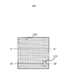
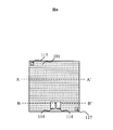
- FIG. 1 is a schematic top view of a first glass substrate, a substrate having a higher thermal conductivity than glass, and a second glass substrate in a gas cell of a glass substrate / a glass substrate laminated substrate having a higher thermal conductivity than glass, respectively.
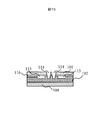
- . 4 and 5 are schematic cross-sectional views taken along lines A-A ′ and B-B ′ in FIG. 1, respectively.
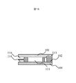
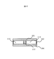
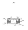
- the gas cell has a stacked structure in which a substrate 102 having a higher thermal conductivity than the glass is disposed between the glass substrate 101 and the glass substrate 104, and the gas cell is an alkali that generates an alkali metal gas on the substrate 102.
- a cavity 111 containing a metal solid or liquid 112 (see FIG. 1) and a flow path (through hole) 113 are arranged in the substrate 102, and the flow path (through hole) 113 is connected to the glass substrate 101 and the glass substrate 104.
- the entrance / exit (two openings) 114 (see FIGS. 2 and 3) is installed. That is, the flow path 113 is a through hole that penetrates through two openings serving as entrances and exits.
- the cavity 111 and the flow path (through hole) 113 are formed by removing a part of the substrate 102.
- the cavity 111 is hermetically sealed by the glass substrate 101 and the glass substrate 104, and laser light is transmitted through the glass substrate 101 and the glass substrate 104.
- a hollow pipe such as a tube is connected to the entrance / exit 114 from the outside, and the heated fluid is poured into the flow path (through hole) 113 to heat the substrate 102.
- the fluid is a gas and a liquid excluding a solid, and is poured into the flow path (through hole) 113 in order to adjust the temperature of the alkali metal gas.
- the alkali metal gas contained in the cavity 111 can be heated to increase the vapor pressure, and the number of alkali metal atoms can be increased.
- the cavity is rectangular, and the flow path (through hole) 113 is disposed so as to surround three sides of the rectangle. The effect is obtained.
- FIGS. 1, 2 and 3 are schematic top views of the gas cell according to the first embodiment on the substrate 102, the glass substrate 101 and the glass substrate 104, respectively.
- 4 and 5 are schematic cross-sectional views taken along lines A-A ′ and B-B ′ in FIG. 1, respectively.
- 6 (a), 6 (b), and 6 (c) show a gas cell manufacturing method according to an embodiment of the present invention, using a cross-sectional view taken along the line B-B 'in FIG.
- the manufacturing method of the glass substrate 104 is omitted because it is the same as the manufacturing method of the glass substrate 101.
- the gas cell according to the present embodiment has a glass, substrate, and glass three-layer structure in which a glass substrate 101 is disposed on the upper surface of the substrate 102 and a glass substrate 104 is disposed on the lower surface.
- a material having higher thermal conductivity than the glass substrate 101 and the glass substrate 104 for example, a semiconductor substrate such as a silicon substrate is used.
- the glass substrate 101 and the glass substrate 104 are made of a material transparent to the laser beam to be irradiated, and are formed on the alkali metal solid or liquid 112 and the alkali metal gas enclosed in the cavity 111 formed on the substrate 102 and the substrate 102.
- the fluid flowing through the flow path 113 is arranged so as not to leak.
- the substrate 102 has a cavity 111 filled with an alkali metal gas, an alkali metal solid or liquid 112 disposed in the cavity 111, and the glass substrate 101 and the glass substrate 104 have an inlet / outlet 114 (see FIG. 2) through which a fluid connected to the flow path is taken in and out. And 3).
- the cavity 111 has a structure penetrating the substrate 102 as viewed from the cross section, and contains the alkali metal gas generated from the alkali metal solid or the liquid 112 (see FIG. 4). Further, the inside of the cavity 111 only needs to be sealed in a region surrounded by the glass substrate 101 and the glass substrate 104, and may be nitrogen gas, rare gas, or a mixed atmosphere in addition to alkali metal gas. In FIG. 1, the shape of the cavity 111 is rectangular, but it may be a region surrounded by other polygons or curves. In this embodiment, laser light is irradiated from the upper glass substrate 101 toward the lower glass 104 substrate, and the magnetic field is measured by passing the laser light through the cavity 111.
- the alkali metal solid or liquid 112 is enclosed in a cavity 111 formed in the substrate 102, and generates an alkali metal gas in the cavity 111 surrounded by the glass substrate 101 and the glass substrate 104.
- the alkali metal solid or liquid 112 may be any material that generates an alkali metal gas, and a material that can generate an alkali metal gas by using a chemical reaction or the like by placing a compound containing an alkali metal or the like is used. Also good.
- the flow path 113 is not necessarily indispensable, but is desirably arranged so as to surround the three sides of the rectangular cavity 111 with a straight line. This is because the heat of the fluid can be transferred to the cavity 111 more efficiently by surrounding the three sides of the rectangle.
- the flow path 113 is configured to penetrate the substrate 102 as viewed from the cross section, and the substrate 102 is heated by flowing a heated fluid from the inlet / outlet 114, thereby heating the alkali metal gas in the cavity 111.
- the alkali metal gas is heated, the saturated vapor pressure increases, so that the number of alkali metal atoms contributing to the magnetic field measurement is increased and the detection sensitivity is increased.
- the substrate can be heated more efficiently than the method of heating glass. Further, compared to the case of using a heater, since no current is used for heating, there is an advantage that the measurement magnetic field is not affected.
- through-holes are respectively arranged in the glass substrate 101 and the glass substrate 104 so as to connect the entrance / exit 114 for taking in and out the fluid to the flow path 113.
- a configuration is adopted in which a fluid heated from the outside is injected into one inlet / outlet and the fluid is discharged from the other inlet / outlet.
- the diameter of the through hole of the entrance / exit 114 is larger than the diameter of the flow path 113.
- the substrate 102 is a silicon substrate having a higher thermal conductivity than glass.
- a substrate doped with impurities such as phosphorus and boron may be used. This has the advantage that the thermal conductivity is increased by impurity doping.
- the pattern of the cavity 111 and the flow path 113 is formed on the mask material 105 formed on the substrate by lithography or the like, and the cavity 111 and the flow path 113 are formed on the substrate 102 by etching or the like.
- a silicon oxide film is used as a mask material, and dry etching using SiF 4 (silicon tetrafluoride) gas is used to make a through hole in the substrate 102 according to a pattern.
- SiF 4 silicon tetrafluoride
- the cross sections of the cavity 111 and the flow path 113 do not have to be vertical, and may be oblique or have a step. Therefore, other approaches, such as KOH wet etching using (potassium hydroxide) solution or the like, or by processing directly the substrate 102 with a laser or a drill or the like, may be formed a cavity 111 and the channel 113.
- the glass substrate 101 and the glass substrate 104 are made of a material transparent to laser light, such as borosilicate glass. Similarly to the substrate 102, a pattern of the entrance / exit 114 is formed in the mask material 105 by lithography or the like, and through holes are formed in the glass substrate 101 and the glass substrate 104 by etching or the like.
- the glass substrate 101, the substrate 102, and the glass substrate 104 are sealed by being bonded or bonded together in a state where an alkali metal solid or liquid 112 is enclosed in the cavity 111.
- an alkali metal solid or liquid 112 is enclosed in the cavity 111.
- the atmosphere at the time of bonding or bonding the glass substrate 101 or the glass substrate 104 may be an inert gas such as nitrogen or a rare gas, and these gases may be simultaneously enclosed in the cavity 111. Encapsulation of these inert gas and rare gas has an effect of suppressing spin scattering of the alkali metal gas.
- the substrate and the substrate, the glass substrate and the substrate may be kept sealed between them, and an adhesive or the like may be used.
- the inlet / outlet 114 is connected to an external heater and pump by piping such as a silicone tube, and flows a heated fluid.
- the shape of the entrance / exit 114 may be a circular shape or the like in accordance with the shape of a silicone tube or the like.
- Example 2 of the present invention will be described with reference to FIGS. 7 and 8 are schematic top views of the substrate 102 and the glass substrate 101, respectively, of the gas cell according to the second embodiment.
- 9 and 10 are schematic cross-sectional views taken along lines A-A ′ and B-B ′ in FIG. 7, respectively.
- the second embodiment is composed of three layers of glass, substrate and glass, as in the first embodiment.
- the cavity 111 is the same as that in the first embodiment.
- FIG. 9 shows, as an example, a schematic cross-sectional view when a through hole is made in the substrate 102 by anisotropic wet etching, and shows a form in which the cross-sectional shape is slanted.
- the method using wet etching has an advantage that the through hole can be formed simply by immersing the substrate in an etching solution, and thus the manufacturing is easy.
- the alkali metal solid or liquid 112 is the same as in the first embodiment.
- the flow path 113 is arranged in a zigzag manner in the horizontal direction with respect to the surface of the substrate 102.
- the flow path so as to meander in this manner, the total length of the flow path can be extended, and the cavity 111 and the path 111 formed by connecting straight lines parallel to the four sides of the rectangular substrate 102 can be combined.
- the surface area of the opposite side can be increased, and the heat of the heated fluid can be transmitted efficiently.
- the channel 113 is configured not to penetrate the substrate. That is, the flow path is in contact with the glass substrate 104 through a part of the substrate. Accordingly, since the three sides of the flow path 113 are formed of a substrate having a higher thermal conductivity than glass, there is an advantage that the heat of the heated fluid can be efficiently transmitted to the substrate.
- the cross section of the flow path 113 does not have to be rectangular, and may be another polygonal shape or a round shape.
- the flow path 113 is disposed on the glass substrate 101 side of the substrate 102, but may of course be disposed on the glass substrate 104 side of the substrate 102. In that case, the entrance / exit 114 is arranged on the glass substrate 104 on the lower surface side.
- the entrance / exit 114 is configured such that a through hole is disposed in the glass substrate 101 and the entrance / exit 114 is connected to the flow path 113.
- piping connected to the outside such as a silicone tube can be integrated, and wiring is facilitated.
- the arrangement of the flow path 113 and the arrangement of the entrance / exit 114 are changed as compared with the first embodiment, but the respective effects are obtained independently.
- an n-type or p-type semiconductor substrate is used as the substrate 102, and a p-type or n-type impurity region 116 is formed in a part of the substrate 102 on the glass substrate 101 side to act as a pn junction diode temperature sensor.
- the diode temperature sensor and the external temperature measurement system are connected by forming and wiring the impurity region 116 on the glass substrate 101 and the temperature sensor terminal 117 at a position in contact with the substrate 102 other than the region. Since this method does not use a magnetic material, there is an advantage that the measurement magnetic field and the like are not affected.
- a temperature sensor is used to detect that the substrate 102 has reached a desired temperature, and then the magnetic field is measured. When measuring the magnetic field, it is desirable not to energize the temperature sensor so as not to be affected by the magnetic field due to the current flowing through the temperature sensor.
- the cavity 111 forms a through hole when viewed from the cross section, and the flow path 113 forms a non-through groove when viewed from the cross section.
- Other methods include changing the amount of shaving, or drawing the pattern of the cavity 111 and the channel 113 on the upper surface of the substrate 102, drawing the pattern of the cavity 111 on the lower surface, and simultaneously performing etching or the like from both sides of the substrate.
- the cavity 111 and the channel 113 may be formed by directly processing the substrate 102 with a laser or a drill. In FIGS.
- the etching is performed twice, the cavity 111 is formed by anisotropic wet etching, and the flow path 113 is formed by isotropic dry etching.
- the diode temperature sensor forms an impurity region 116 on one side of the substrate 102 by lithography or the like and ion implantation or thermal diffusion.
- the entrance / exit 114 is the same as that in the first embodiment, and in this embodiment, the entrance / exit 114 is disposed only in the glass substrate 101. Further, the temperature sensor terminal 117 connected to the diode temperature sensor and the outside forms a through hole in the glass substrate 101 so that the impurity region 116 of the substrate 102 and the region other than the region of the substrate 102 are exposed.
- the processing of the glass substrate 104 is unnecessary except for the processing of cutting to the size of the gas cell, the effect of reducing the number of processing of the glass substrate, the piping connected to the gas cell entrance and exit when a plurality of gas cells are arranged, and There is an effect that the wiring connected to the temperature sensor can be concentrated on one side.
- the bonding or bonding of the glass substrate 101, the substrate 102, and the glass substrate 104 is the same as in the first embodiment.
- the flow path 113 meanders, the flow path 113 is a non-through groove when viewed from a cross section, the entrance / exit 114 is arranged on the same surface of one glass substrate, or a temperature sensor is provided. Even if one of these is applied to the gas cell of the first embodiment, it is possible to obtain a unique effect of each configuration.
- FIG. 11 is a schematic top view of the substrate 102 in the gas cell according to the third embodiment.
- 12 and 13 are schematic cross-sectional views taken along lines A-A ′ and B-B ′ in FIG. 11, respectively.
- the glass / substrate / glass three-layer structure is used in the third embodiment.
- the cavity 111 is the same as that in the first embodiment.
- the alkali metal solid or liquid 112 is the same as in the first embodiment.
- the flow path 113 is disposed so as to surround the cavity 111 in parallel with the four sides of the substrate 102.
- the flow path 113 is bifurcated from one of the two inlets / outlets 114 and is arranged so as to be connected to one place in the vicinity of the other inlet / outlet 114 around the cavity 111.
- the flow path 113 is arranged in a rectangular shape, but other polygons or curves may be used.
- the cross-sectional shape of the flow path 113 is the same as that of the second embodiment. As a result, the entire periphery of the cavity 111 is surrounded by the flow path 113, and the alkali metal gas in the cavity 111 can be heated more efficiently than in the first and second embodiments.
- the entrance / exit 114 is the same as in the second embodiment.
- a semiconductor pn junction diode temperature sensor is used as in the second embodiment.
- an n-type or p-type semiconductor substrate is used as the substrate 102, and a p-type or n-type impurity region 116 is formed on the entire surface of the substrate 102 on the glass substrate 101 side, thereby acting as a diode temperature sensor.
- the temperature sensor terminal 117 is formed on the glass substrate 101 and the glass substrate 104 and wired. The effect is the same as in the second embodiment, but there is an advantage that the number of manufacturing steps can be reduced as described in the next section.
- the processing of the substrate 102 requires etching of the cavity 111 and the flow path 113 as in the second embodiment, but in this embodiment, both the cavity 111 and the flow path 113 were performed by anisotropic wet etching. Examples are shown in FIGS. If the area of the flow path 113 is made smaller than the area of the cavity 111, the cross section becomes a slope due to the anisotropy of wet etching, and the cavity 111 penetrates through the cross section as viewed from the cross section by one wet etching process. It is possible to form a non-through hole when the channel 113 is viewed from a cross section. As a result, there is an advantage that the fabrication becomes easy.
- the fabrication of the temperature sensor is the same as that of the second embodiment, but the present embodiment is different in that an impurity region is formed on the entire surface of the substrate without using lithography or the like. Thereby, there is an advantage that a process such as lithography becomes unnecessary.
- the processing of the glass substrate 101 and the glass substrate 104 is the same as in the second embodiment, except that the temperature sensor terminals 117 are arranged on the glass substrate 101 and the glass substrate 104, respectively.
- the bonding or bonding of the glass substrate 101, the substrate 102, and the glass substrate 104 is the same as in the first embodiment.
- the flow path 113 is branched and coupled to surround the entire periphery of the cavity 111, or a temperature sensor is provided. Even if one of these is applied to the gas cell of the first embodiment, the unique effects of each configuration are provided. Can be obtained.
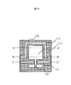
- FIG. 14 is a schematic top view of a gas cell according to the fourth embodiment.
- FIG. 16, and FIG. 17 are schematic cross-sectional views taken along lines A-A ′, B-B ′, and C-C ′ in FIG. 14, respectively.
- the glass / substrate / glass three-layer structure is used.
- the cavity 111 has a structure penetrating the substrate and contains an alkali metal gas generated from an alkali metal solid or liquid 112.
- the alkali metal solid or liquid 112 is disposed in a portion different from the position where the laser passes, and is configured so that the alkali metal solid or liquid 112 does not move to the position where the laser passes or is difficult to move. This has an effect of suppressing the transmitted light from being affected by the alkali metal solid or the liquid 112 when the laser light is transmitted through the cavity 111.
- the alkali metal solid or liquid 112 is the same as in the first embodiment.
- the cavity 111 includes a first region through which laser light passes through the cavity 111, and a second region in which an alkali metal solid or liquid that is a source of alkali metal gas is disposed, and these regions. This is realized by connecting each other in a region narrower than each region.
- the flow path 113 is arranged around the position where the laser beam of the cavity 111 passes. Further, the channel 113 has non-penetrating grooves arranged above and below the substrate 102 when viewed from the cross section, puts a fluid heated from one side, and arranges a through hole on the opposite side, thereby lowering the channel from the upper or lower channel. The fluid is discharged from the original side through the side or upper flow path. Thereby, the full length of a flow path can be extended and a board
- the entrance / exit 114 is arranged on the side surface of the substrate 102 and is configured to take in and out the heated fluid by connecting a silicone tube or the like. Further, by arranging the entrance / exit 114 in the substrate 102, there is an advantage that the processing of the glass substrate 101 or the glass substrate 104 becomes unnecessary.
- the heat insulating layer 115 is disposed between the portion of the cavity 111 through which the laser beam passes and the portion holding the alkali metal solid or the liquid 112.
- the heat insulating layer 115 is made of a material that does not transmit heat to the heat insulating layer 115 formed between the glass substrate 101 and the glass substrate 104 by making a through hole in the substrate, for example, this heat insulating layer is used to apply vacuum or gas to a hermetically sealed space. It is a filled layer.
- This heat insulating layer 115 prevents only the portion through which the laser light passes when the substrate 102 is heated by flowing the heated fluid through the flow path 113 and does not heat the alkali metal solid or the liquid 112.
- the heat insulating layer 115 is desirably provided between the flow path 113 and the second region where the alkali metal gas source is disposed.
- the heat insulating layer may be made of a material that does not easily transfer heat, but is preferably a cavity for the convenience of the manufacturing process.
- a pattern of the cavity 111 and the flow path 113 is formed on the substrate 102 by lithography or the like, and the cavity 111 and the flow path 113 are formed on the substrate 102 by etching or the like.
- the cross sections of the cavity 111 and the flow path 113 do not have to be vertical, and may be oblique or have a step.
- the cavity 111 is formed with a through hole when viewed from the cross section, and the flow path 113 is formed with a non-through groove on the glass substrate 101 side and the glass substrate 104 side of the substrate 102 as viewed from the cross section.
- there is a method of forming the channel 113 on the upper and lower surfaces of the substrate 102 by forming the cavity 111 and the channel 113 on one side of the substrate 102 and forming the channel 113 on the other side of the substrate 102.
- Processing of the glass substrate 101 and the glass substrate 104 is not necessary for the entrance / exit 114.
- the temperature sensor is the same as in the first embodiment or the second embodiment.
- the bonding or bonding of the glass substrate 101, the substrate 102, and the glass substrate 104 is the same as in the first embodiment.
- the shape of the cavity is devised, the flow path is formed in two layers, the entrance / exit is provided in the substrate 102, and the heat insulating layer is provided.
- One of these is applied to the gas cell of the first embodiment. However, it is possible to obtain the unique effects of each configuration.
- FIG. 18 is a schematic top view of the gas cell substrate 102 according to the fifth embodiment.
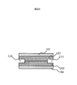
- 19 and 20 are schematic cross-sectional views taken along lines A-A ′ and B-B ′ in FIG. 18, respectively.
- 21 (a), (b), (c), (d), and (e) show a method of manufacturing the substrate 102 according to the present embodiment, using a cross-sectional view taken along the line BB 'in FIG. .
- the manufacturing method of the substrate 103 is the same as that of the substrate 102
- the manufacturing method of the glass substrate 101 and the glass substrate 104 is omitted because it is the same as that of the first embodiment.
- the gas cell according to the present embodiment has a glass / substrate / substrate / glass four-layer structure in which a glass substrate 101 is disposed on the upper surface of the substrate 102 and the substrate 103 bonded together and a glass substrate 104 is disposed on the lower surface.
- a glass substrate 101 is disposed on the upper surface of the substrate 102 and the substrate 103 bonded together and a glass substrate 104 is disposed on the lower surface.
- two substrates are used, but three or more substrates may be used.
- a material having a higher thermal conductivity than the glass substrate 101 and the glass substrate 104 for example, a semiconductor substrate such as a silicon substrate is used.
- the glass substrate 101 and the glass substrate 104 are the same as in the first embodiment.
- the cavity 111 has a structure penetrating the substrate 102 and the substrate 103 and contains an alkali metal gas generated from the alkali metal solid or the liquid 112. Further, the inside of the cavity 111 only needs to be sealed in a region surrounded by the glass substrate 101 and the glass substrate 104, and may be nitrogen gas, rare gas, or a mixed atmosphere in addition to alkali metal gas.
- the shape of the cavity 111 is rectangular, but it may be a region surrounded by other polygons or curves.
- laser light is irradiated from the upper glass substrate 101 toward the lower glass substrate 104, and the magnetic field is measured by passing the laser light through the cavity 111.
- the alkali metal solid or liquid 112 is the same as in the first embodiment.
- the flow path 113 is disposed so as to surround three sides of the rectangular cavity 111 with a straight line.
- the flow path 113 is configured not to penetrate the substrate 102 and the substrate 103 when viewed in cross section, and the flow path 113 is formed by bonding the non-penetrating grooves formed in the substrate 102 and the substrate 103 so as to face each other.
- the heated fluid flowing through the flow path 113 does not contact the glass substrate 101 and the glass substrate 104, and is in contact with each glass substrate via both the glass substrate and a part of the substrates 102 and 103. Therefore, the heat of the fluid can be efficiently transmitted only to the substrate.
- the entrance / exit 114 is arranged on the side surfaces of the substrate 102 and the substrate 103, and a fluid heated from the outside is injected into one of the entrances and exits from the other entrance / exit.
- the substrate 102 and the substrate 103 are silicon substrates having higher thermal conductivity than glass.
- the substrate may be subjected to treatment such as impurity doping in order to enhance thermal conduction.
- a pattern of the cavity 111 is formed in the mask material 105 formed on the substrate 102 and the substrate 103 by lithography or the like, and the cavity 111 is formed in the substrate 102 and the substrate 103 by dry etching or the like.
- the cross section of the cavity 111 does not need to be vertical, and may be oblique or stepped.
- a new mask material 105 is formed on the substrate 102 and the substrate 103, a pattern of the channel 113 is formed on the substrate 102 and the mask material 105 on the substrate 103 by lithography or the like, and the substrate 102 and the substrate are formed by dry etching or the like.
- a flow path 113 is formed in 103.
- the cross section of the channel 113 does not need to be vertical, and may be oblique or have a step.
- the pattern of the cavity 111 and the flow path 113 is drawn on the upper surface of the substrate 102 in addition to the manufacturing procedure example. There is a method of drawing a pattern of the cavity 111 on the lower surface and simultaneously performing wet etching or the like from both sides of the substrate.
- the cavity 111 and the channel 113 may be formed by directly processing the substrate 102 with a laser or a drill.
- the glass substrate 101 and the glass substrate 104 are the same as in the first embodiment.
- the glass substrate 101, the substrate 102, the substrate 103, and the glass substrate 104 are bonded or bonded together in a state in which an alkali metal solid or liquid 112 is enclosed in the cavity 111 and sealed.
- an alkali metal solid or liquid 112 is enclosed in the cavity 111 and sealed.
- the atmosphere at the time of bonding or bonding the glass substrate 101 or the glass substrate 104 may be an inert gas such as nitrogen or a rare gas, and these gases may be simultaneously enclosed in the cavity 111.
- the substrate and the substrate, the glass substrate and the substrate may be kept sealed between them, and an adhesive or the like may be used.
- a four-layer structure is adopted so as not to contact both glass substrates, and entrances / exits are provided in the substrates 102 and 103.
- each structure is unique. The effect of can be obtained.
- FIG. 22 is a schematic top view of a gas cell according to the sixth embodiment.
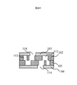
- 23 and 24 are schematic cross-sectional views taken along lines A-A ′ and B-B ′ in FIG. 22, respectively.
- the glass / substrate / substrate / glass four-layer structure is used.
- the cavity 111 is the same as in the fifth embodiment.
- the alkali metal solid or liquid 112 is the same as in the first embodiment.
- the flow path 113 is disposed so as to surround the cavity 111 in parallel with the substrate 102 and the substrate 103.
- the through-hole is disposed in the flow path 113 as viewed from the cross section so as to alternately pass through the substrate 102 and the substrate 103. This has the effect of extending the entire path length of the flow path by meandering the flow path and increasing the surface area facing the cavity rather than connecting straight lines parallel to the four sides of the substrate 102 when viewed from above.
- the distance between the flow path 113 and the cavity 111 can be made closer than in the second embodiment, and the heat can be efficiently transferred to the alkali in the cavity. Can communicate to metal gas.
- the entrance / exit 114 is the same as in the first embodiment. In FIG. 19, one entrance / exit 114 is provided in each of the glass substrate 101 and the glass substrate 104, but two entrances / exits may be integrated into one glass substrate.
- the processing of the substrate 102 and the substrate 103 is the same as that in the first embodiment, and after forming the cavity 111 and the flow path 113, the substrate 102 and the substrate 103 are bonded or bonded.
- Processing of the glass substrate 101 and the glass substrate 104 is the same as in the first or second embodiment. Adhesion and bonding between the glass substrate 101 and the substrate 102 and between the substrate 103 and the glass substrate 104 are the same as in the first embodiment.
- Example 6 the flow path is meandered with a four-layer structure, but even when applied to the gas cell of Example 1, a unique effect can be obtained.
- FIG. 25 is a schematic top view of a gas cell according to the seventh embodiment.
- 26 and 27 are schematic cross-sectional views taken along lines A-A ′ and B-B ′ in FIG. 25, respectively.
- the seventh embodiment is composed of glass, a substrate, a substrate, and four glass layers as in the fifth embodiment.
- the cavity 111 is the same as that in the fourth embodiment.
- the alkali metal solid or liquid 112 is the same as in the first embodiment.
- the flow paths 113 are arranged in the same manner as in the fourth embodiment, but the flow paths 113 are formed on the substrate 102 and the substrate 103, and the respective flow paths 113 are shifted so as not to be connected except at the end opposite to the entrance / exit 114. Deploy. At the opposite end of the entrance / exit 114, the substrate 102 and the channel 113 of the substrate 103 are connected. That is, the flow path 113 has a two-layer structure, and this has the same effect as the fourth embodiment.
- Example 6 the heat insulating layer 115 is provided as in Example 4. However, in Example 6, the heat insulating layer 115 is not only provided between the flow path 113 and the second region where the alkali metal gas source is disposed, but is disposed so as to surround the flow path. Has been. In addition to the effects of the fourth embodiment, the heat of the fluid leaks to the outside and the influence of the outside air can be reduced, and the alkali metal gas in the cavity 111 can be warmed efficiently.
- the entrance / exit 114 is the same as in the first embodiment.
- the processing of the substrate 102 and the substrate 103 is the same as in the sixth embodiment.
- Processing of the glass substrate 101 and the glass substrate 104 is the same as in the first embodiment.
- Adhesion and bonding between the glass substrate 101 and the substrate 102 and between the substrate 103 and the glass substrate 104 are the same as in the first embodiment.
- Example 7 the shape of the cavity was devised, a four-layer structure was used, the flow path was formed in two layers, and a heat insulating layer was provided. However, even if one of these is applied to the gas cell of Example 1, each configuration The inherent effect of can be obtained.
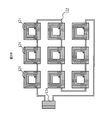
- Example 8 of the present invention will be described with reference to FIG. 28 a plurality of gas cells 121 configured according to the first to seventh embodiments are arranged in an array, and sequentially connected by a hollow pipe 122 such as a silicone tube, and the external heater for heating the fluid and the fluid are connected to the hollow pipe.
- a hollow pipe 122 such as a silicone tube
- the system which circulates the heated fluid in series by connecting a gas cell array to the pump 124 to flow is shown.
- the gas cell 121 according to the fifth embodiment is illustrated as an example, but the gas cell 121 according to another embodiment may be used, or a plurality of types of gas cells 121 may be used in combination. .
- FIG. 25 nine gas cells are arranged in an array, but the number of gas cells to be arranged is not limited.
- the pipe 122 is hollow and uses a non-magnetic material such as a silicone tube.
- the shape is set so as to be in close contact with the entrance / exit 114 arranged in the gas cell 121 and is fixed with an adhesive or the like.
- the external heater and pump 124 are arranged outside the magnetic shield so as not to affect the magnetic field measured by the magnetometer.
- the external heater and the pump 124 are arranged at one place, but the external heater and the pump may be appropriately inserted at a plurality of places.
- the piping 122 is connected to the output of the external heater and the pump 124 and is connected to one inlet / outlet 114 of the gas cell 121.
- the other inlet / outlet 114 of the gas cell 121 is connected to one inlet / outlet 114 of the next gas cell 121, and this is repeated for the required number of gas cells, and the last gas cell inlet / outlet 114 is connected again to the input of the external heater and pump 124.
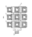
- FIG. 29 shows an external heater in which a plurality of gas cells 121 configured according to the first to seventh embodiments are arranged in an array, and a hollow pipe 122 such as a silicone tube is branched and connected to each gas cell 121 to heat the fluid. And the system which circulates the heated fluid in parallel by connecting a gas cell array to the pump 124 which flows the fluid into the hollow pipe is shown.
- the gas cell 121 is the same as that in the eighth embodiment.
- the pipe 122 is the same as that of the eighth embodiment, and a branch is provided in the middle and connected to the gas cell 121 in parallel. Since the flow rate of the piping decreases as the distance from the external heater and the pump 124 increases, the cross-sectional area of the piping 122 has a plurality of cross-sectional areas such as decreasing as the distance from the external heater and the pump increases. Compared to the eighth embodiment in which the gas cells 121 are connected in series, the fluid heated by the heater flows directly into each gas cell 121, so that there is an advantage that the time until each gas cell is heated is shortened.
- the external heater and pump 124 are the same as in the eighth embodiment.
- a pipe 122 is connected to the output of the external heater and pump 124, a branch is provided in the middle of the pipe 122, and the branched pipe 122 is connected to one inlet / outlet 114 of the gas cell 121.
- the other inlet / outlet port 114 of the gas cell 121 is aggregated in the pipe 122 and connected to the input of the external heater and the pump 124 in the reverse order.
- Example 10 of the present invention will be described with reference to FIG.
- a plurality of gas cells 121 configured according to the first to seventh embodiments are arranged in an array on a substrate 123 with piping, and the inlet / outlet 114 of each gas cell 121 and the piping on the substrate 123 with piping are connected.
- the substrate with piping 123 is connected to an external heater that warms the fluid by the piping 122 and a gas cell array connected to a pump 124 that flows the fluid into the hollow piping.
- the gas cell 121 is the same as that in the eighth embodiment.
- the inlet / outlet port 114 of the gas cell 121 is preferably arranged on the lower surface of the gas cell.
- the pipe 122 is the same as that in the eighth embodiment.
- the substrate 123 with piping has a flow path through which the heated fluid passes inside the substrate, and is configured by plastic molding, for example.
- the substrate 123 with piping needs to be transparent to the laser light at least at the part through which the laser light passes.
- the substrate 123 with piping and the gas cell 121 are connected with an adhesive or the like, and at the same time, connected to the inlet / outlet port 114 on the lower surface of the gas cell and the piping portion of the substrate 123 with piping, or using the piping 122, the inlet / outlet port 114 of the gas cell and the substrate 123 with piping are connected. Connect to the piping section.
- the complexity of piping can be eliminated by connecting a combination of series and parallel.
- the use of the substrate 123 with piping has an effect of fixing the gas cells 121 and the piping 122 arranged in an array. These effects are independent of each other, and the connection of the pipes in a series and parallel combination and the use of the board with the pipes may be performed separately.
- the external heater and pump 124 are the same as in the eighth embodiment.
- the output of the external heater and pump 124 and the substrate 123 with piping are connected by the piping 122, and the heated fluid is caused to flow through the flow path of the gas cell 121 disposed on the substrate 123 with piping. 121 is heated.
- the gas cell 121 is arranged on the substrate 123 with piping in combination in series and parallel.
Landscapes
- Physics & Mathematics (AREA)
- Engineering & Computer Science (AREA)
- Power Engineering (AREA)
- Condensed Matter Physics & Semiconductors (AREA)
- General Physics & Mathematics (AREA)
- Micromachines (AREA)
Abstract
Priority Applications (3)
| Application Number | Priority Date | Filing Date | Title |
|---|---|---|---|
| PCT/JP2011/055880 WO2012124036A1 (fr) | 2011-03-14 | 2011-03-14 | Appareil de mesure de champ magnétique |
| JP2013504431A JP5444502B2 (ja) | 2011-03-14 | 2011-03-14 | 磁場計測装置 |
| US13/980,579 US20130341745A1 (en) | 2011-03-14 | 2011-03-14 | Magnetic Field Measurement Apparatus |
Applications Claiming Priority (1)
| Application Number | Priority Date | Filing Date | Title |
|---|---|---|---|
| PCT/JP2011/055880 WO2012124036A1 (fr) | 2011-03-14 | 2011-03-14 | Appareil de mesure de champ magnétique |
Publications (1)
| Publication Number | Publication Date |
|---|---|
| WO2012124036A1 true WO2012124036A1 (fr) | 2012-09-20 |
Family
ID=46830170
Family Applications (1)
| Application Number | Title | Priority Date | Filing Date |
|---|---|---|---|
| PCT/JP2011/055880 Ceased WO2012124036A1 (fr) | 2011-03-14 | 2011-03-14 | Appareil de mesure de champ magnétique |
Country Status (3)
| Country | Link |
|---|---|
| US (1) | US20130341745A1 (fr) |
| JP (1) | JP5444502B2 (fr) |
| WO (1) | WO2012124036A1 (fr) |
Cited By (9)
| Publication number | Priority date | Publication date | Assignee | Title |
|---|---|---|---|---|
| WO2014132651A1 (fr) * | 2013-02-28 | 2014-09-04 | 国立大学法人京都大学 | Procédé de production d'une cellule de métal alcalin, procédé de production de métal alcalin et cellule contenant un métal alcalin gazeux |
| JP2016029362A (ja) * | 2014-07-24 | 2016-03-03 | セイコーエプソン株式会社 | ガスセルおよび磁気測定装置 |
| JP2022547323A (ja) * | 2019-10-21 | 2022-11-11 | クオンタム ヴァリー アイデアズ ラボラトリーズ | 散乱断面積を減少させた蒸気セルおよびその製造方法 |
| WO2023053655A1 (fr) * | 2021-10-01 | 2023-04-06 | 浜松ホトニクス株式会社 | Module de capteur magnétique à excitation optique |
| WO2023079767A1 (fr) * | 2021-11-02 | 2023-05-11 | 株式会社多摩川ホールディングス | Pile à gaz et son procédé de fabrication |
| JP2024517080A (ja) * | 2021-04-13 | 2024-04-19 | クオンタム ヴァリー アイデアズ ラボラトリーズ | 連結可能な蒸気セル |
| JP2025531157A (ja) * | 2022-09-13 | 2025-09-19 | クオンタム ヴァリー アイデアズ ラボラトリーズ | スタック層により規定された本体を有する蒸気セルにおける電界の制御 |
| JP2025533455A (ja) * | 2022-09-13 | 2025-10-07 | クオンタム ヴァリー アイデアズ ラボラトリーズ | 蒸気セルにおける電界の制御 |
| JP7832374B1 (ja) * | 2025-01-10 | 2026-03-17 | 浜松ホトニクス株式会社 | 磁気測定装置 |
Families Citing this family (6)
| Publication number | Priority date | Publication date | Assignee | Title |
|---|---|---|---|---|
| US9310447B2 (en) * | 2011-11-18 | 2016-04-12 | Hitachi, Ltd. | Magnetic field measuring apparatus and method for manufacturing same |
| US9366735B2 (en) * | 2012-04-06 | 2016-06-14 | Hitachi, Ltd. | Optical pumping magnetometer |
| US10145909B2 (en) * | 2014-11-17 | 2018-12-04 | Seiko Epson Corporation | Magnetism measuring device, gas cell, manufacturing method of magnetism measuring device, and manufacturing method of gas cell |
| JP2018004430A (ja) * | 2016-07-01 | 2018-01-11 | セイコーエプソン株式会社 | ガスセルの製造方法、磁気計測装置の製造方法、およびガスセル |
| US11112298B2 (en) * | 2019-11-27 | 2021-09-07 | Quantum Valley Ideas Laboratories | Vapor cells for imaging of electromagnetic fields |
| CN111964657A (zh) * | 2020-07-15 | 2020-11-20 | 北京航天控制仪器研究所 | 一种用于原子陀螺仪的双层真空保温结构 |
Citations (3)
| Publication number | Priority date | Publication date | Assignee | Title |
|---|---|---|---|---|
| JPS5752201A (en) * | 1980-07-31 | 1982-03-27 | Yokogawa Hewlett Packard Ltd | Resonance cavity |
| US7292111B2 (en) * | 2004-04-26 | 2007-11-06 | Northrop Grumman Corporation | Middle layer of die structure that comprises a cavity that holds an alkali metal |
| JP2009283526A (ja) * | 2008-05-20 | 2009-12-03 | Epson Toyocom Corp | ガスセルの製造方法及びガスセル |
-
2011
- 2011-03-14 JP JP2013504431A patent/JP5444502B2/ja not_active Expired - Fee Related
- 2011-03-14 US US13/980,579 patent/US20130341745A1/en not_active Abandoned
- 2011-03-14 WO PCT/JP2011/055880 patent/WO2012124036A1/fr not_active Ceased
Patent Citations (3)
| Publication number | Priority date | Publication date | Assignee | Title |
|---|---|---|---|---|
| JPS5752201A (en) * | 1980-07-31 | 1982-03-27 | Yokogawa Hewlett Packard Ltd | Resonance cavity |
| US7292111B2 (en) * | 2004-04-26 | 2007-11-06 | Northrop Grumman Corporation | Middle layer of die structure that comprises a cavity that holds an alkali metal |
| JP2009283526A (ja) * | 2008-05-20 | 2009-12-03 | Epson Toyocom Corp | ガスセルの製造方法及びガスセル |
Cited By (17)
| Publication number | Priority date | Publication date | Assignee | Title |
|---|---|---|---|---|
| WO2014132651A1 (fr) * | 2013-02-28 | 2014-09-04 | 国立大学法人京都大学 | Procédé de production d'une cellule de métal alcalin, procédé de production de métal alcalin et cellule contenant un métal alcalin gazeux |
| JP2016029362A (ja) * | 2014-07-24 | 2016-03-03 | セイコーエプソン株式会社 | ガスセルおよび磁気測定装置 |
| JP2022547323A (ja) * | 2019-10-21 | 2022-11-11 | クオンタム ヴァリー アイデアズ ラボラトリーズ | 散乱断面積を減少させた蒸気セルおよびその製造方法 |
| JP7728748B2 (ja) | 2019-10-21 | 2025-08-25 | クオンタム ヴァリー アイデアズ ラボラトリーズ | 散乱断面積を減少させた蒸気セルおよびその製造方法 |
| JP7603174B2 (ja) | 2021-04-13 | 2024-12-19 | クオンタム ヴァリー アイデアズ ラボラトリーズ | 連結可能な蒸気セル |
| JP7809723B2 (ja) | 2021-04-13 | 2026-02-02 | クオンタム ヴァリー アイデアズ ラボラトリーズ | 内部キャビティに対するターゲット3次元ボリュームを定める層のスタックを有する蒸気セル |
| JP2024517080A (ja) * | 2021-04-13 | 2024-04-19 | クオンタム ヴァリー アイデアズ ラボラトリーズ | 連結可能な蒸気セル |
| JP2024517082A (ja) * | 2021-04-13 | 2024-04-19 | クオンタム ヴァリー アイデアズ ラボラトリーズ | キャビティのアレイを有する蒸気セル |
| JP2024517081A (ja) * | 2021-04-13 | 2024-04-19 | クオンタム ヴァリー アイデアズ ラボラトリーズ | 内部キャビティに対するターゲット3次元ボリュームを定める層のスタックを有する蒸気セル |
| JP7567068B2 (ja) | 2021-04-13 | 2024-10-15 | クオンタム ヴァリー アイデアズ ラボラトリーズ | キャビティのアレイを有する蒸気セル |
| JP2023053498A (ja) * | 2021-10-01 | 2023-04-13 | 浜松ホトニクス株式会社 | 光励起磁気センサモジュール |
| JP7768716B2 (ja) | 2021-10-01 | 2025-11-12 | 浜松ホトニクス株式会社 | 光励起磁気センサモジュール |
| WO2023053655A1 (fr) * | 2021-10-01 | 2023-04-06 | 浜松ホトニクス株式会社 | Module de capteur magnétique à excitation optique |
| WO2023079767A1 (fr) * | 2021-11-02 | 2023-05-11 | 株式会社多摩川ホールディングス | Pile à gaz et son procédé de fabrication |
| JP2025531157A (ja) * | 2022-09-13 | 2025-09-19 | クオンタム ヴァリー アイデアズ ラボラトリーズ | スタック層により規定された本体を有する蒸気セルにおける電界の制御 |
| JP2025533455A (ja) * | 2022-09-13 | 2025-10-07 | クオンタム ヴァリー アイデアズ ラボラトリーズ | 蒸気セルにおける電界の制御 |
| JP7832374B1 (ja) * | 2025-01-10 | 2026-03-17 | 浜松ホトニクス株式会社 | 磁気測定装置 |
Also Published As
| Publication number | Publication date |
|---|---|
| US20130341745A1 (en) | 2013-12-26 |
| JP5444502B2 (ja) | 2014-03-19 |
| JPWO2012124036A1 (ja) | 2014-07-17 |
Similar Documents
| Publication | Publication Date | Title |
|---|---|---|
| JP5444502B2 (ja) | 磁場計測装置 | |
| CN102576721B (zh) | 具有三维微结构的热电换能器和制造该换能器的方法 | |
| Yang et al. | A novel multi-layer manifold microchannel cooling system for concentrating photovoltaic cells | |
| CN102947683B (zh) | 多层薄膜热电堆及采用该多层薄膜热电堆的辐射温度计、多层薄膜热电堆的制造方法 | |
| Roth et al. | Heat transfer in freestanding microchannels with in-line and staggered pin fin structures with clearance | |
| US20180236447A1 (en) | Electronic device with integrated temperature sensor and manufacturing method thereof | |
| US10741740B2 (en) | Thermo-electric generator | |
| CN104412082A (zh) | Ir热电堆探测器 | |
| US10365226B2 (en) | Microfluidic optical fluid sensor | |
| CN102884627A (zh) | 非制冷红外检测器及用于制造非制冷红外检测器的方法 | |
| IL266815B2 (en) | Temperature control device | |
| CN107686093B (zh) | 半导体气体感测装置的制作方法及其半导体气体感测装置 | |
| CN114572930B (zh) | 基于mems工艺微尺度流动换热高精度集成测试方法 | |
| JP4950513B2 (ja) | 赤外線デバイス集積装置の製造方法 | |
| Kwon et al. | Development of a Hybrid Single/Two-phase Capillary-based Micro-cooler using Copper Inverse Opals Wick with Silicon 3D Manifold for High-Heat-Flux Cooling Application | |
| JP2004340758A (ja) | 微細流路およびこれを含むマイクロ化学チップ | |
| CN104412083B (zh) | 红外传感器设备和用于制造红外传感器设备的方法 | |
| CN115046969B (zh) | 包括具有集成光电二极管的光流控传感器的器件 | |
| CN108458783A (zh) | 一种热电式激光功率探头及其制造方法 | |
| CN115597714A (zh) | 用于检测引导热辐射的传感器和方法 | |
| JP4765663B2 (ja) | 赤外線通信用モジュールの製造方法 | |
| KR20090070878A (ko) | 기울기 센서 및 이의 제조방법 | |
| CN120869279B (zh) | 一种热堆式流量传感器及其制造方法 | |
| Kermani | Manifold micro-channel cooling of photovoltaic cells for high efficiency solar energy conversion systems | |
| Dhillon et al. | Integrating coherent porous silicon as a wicking structure in the mems based fabrication of a vertically wicking micro-columnated loop heat pipe |
Legal Events
| Date | Code | Title | Description |
|---|---|---|---|
| 121 | Ep: the epo has been informed by wipo that ep was designated in this application |
Ref document number: 11860919 Country of ref document: EP Kind code of ref document: A1 |
|
| ENP | Entry into the national phase |
Ref document number: 2013504431 Country of ref document: JP Kind code of ref document: A |
|
| WWE | Wipo information: entry into national phase |
Ref document number: 13980579 Country of ref document: US |
|
| NENP | Non-entry into the national phase |
Ref country code: DE |
|
| 122 | Ep: pct application non-entry in european phase |
Ref document number: 11860919 Country of ref document: EP Kind code of ref document: A1 |