WO2012124164A1 - 電磁継電器 - Google Patents
電磁継電器 Download PDFInfo
- Publication number
- WO2012124164A1 WO2012124164A1 PCT/JP2011/057131 JP2011057131W WO2012124164A1 WO 2012124164 A1 WO2012124164 A1 WO 2012124164A1 JP 2011057131 W JP2011057131 W JP 2011057131W WO 2012124164 A1 WO2012124164 A1 WO 2012124164A1
- Authority
- WO
- WIPO (PCT)
- Prior art keywords
- contact
- electromagnetic relay
- contact piece
- wall
- piece
- Prior art date
- Legal status (The legal status is an assumption and is not a legal conclusion. Google has not performed a legal analysis and makes no representation as to the accuracy of the status listed.)
- Ceased
Links
Images


Classifications
-
- H—ELECTRICITY
- H01—ELECTRIC ELEMENTS
- H01H—ELECTRIC SWITCHES; RELAYS; SELECTORS; EMERGENCY PROTECTIVE DEVICES
- H01H9/00—Details of switching devices, not covered by groups H01H1/00 - H01H7/00
- H01H9/30—Means for extinguishing or preventing arc between current-carrying parts
- H01H9/44—Means for extinguishing or preventing arc between current-carrying parts using blow-out magnet
-
- H—ELECTRICITY
- H01—ELECTRIC ELEMENTS
- H01H—ELECTRIC SWITCHES; RELAYS; SELECTORS; EMERGENCY PROTECTIVE DEVICES
- H01H50/00—Details of electromagnetic relays
-
- H—ELECTRICITY
- H01—ELECTRIC ELEMENTS
- H01H—ELECTRIC SWITCHES; RELAYS; SELECTORS; EMERGENCY PROTECTIVE DEVICES
- H01H50/00—Details of electromagnetic relays
- H01H50/16—Magnetic circuit arrangements
- H01H50/36—Stationary parts of magnetic circuit, e.g. yoke
- H01H50/38—Part of main magnetic circuit shaped to suppress arcing between the contacts of the relay
-
- H—ELECTRICITY
- H01—ELECTRIC ELEMENTS
- H01H—ELECTRIC SWITCHES; RELAYS; SELECTORS; EMERGENCY PROTECTIVE DEVICES
- H01H50/00—Details of electromagnetic relays
- H01H50/54—Contact arrangements
-
- H—ELECTRICITY
- H01—ELECTRIC ELEMENTS
- H01H—ELECTRIC SWITCHES; RELAYS; SELECTORS; EMERGENCY PROTECTIVE DEVICES
- H01H9/00—Details of switching devices, not covered by groups H01H1/00 - H01H7/00
- H01H9/30—Means for extinguishing or preventing arc between current-carrying parts
- H01H9/40—Multiple main contacts for the purpose of dividing the current through, or potential drop along, the arc
-
- H—ELECTRICITY
- H01—ELECTRIC ELEMENTS
- H01H—ELECTRIC SWITCHES; RELAYS; SELECTORS; EMERGENCY PROTECTIVE DEVICES
- H01H9/00—Details of switching devices, not covered by groups H01H1/00 - H01H7/00
- H01H9/30—Means for extinguishing or preventing arc between current-carrying parts
- H01H9/44—Means for extinguishing or preventing arc between current-carrying parts using blow-out magnet
- H01H9/443—Means for extinguishing or preventing arc between current-carrying parts using blow-out magnet using permanent magnets
-
- H—ELECTRICITY
- H01—ELECTRIC ELEMENTS
- H01H—ELECTRIC SWITCHES; RELAYS; SELECTORS; EMERGENCY PROTECTIVE DEVICES
- H01H50/00—Details of electromagnetic relays
- H01H50/02—Bases; Casings; Covers
-
- H—ELECTRICITY
- H01—ELECTRIC ELEMENTS
- H01H—ELECTRIC SWITCHES; RELAYS; SELECTORS; EMERGENCY PROTECTIVE DEVICES
- H01H50/00—Details of electromagnetic relays
- H01H50/16—Magnetic circuit arrangements
- H01H50/18—Movable parts of magnetic circuits, e.g. armature
- H01H50/24—Parts rotatable or rockable outside coil
- H01H50/26—Parts movable about a knife edge
-
- H—ELECTRICITY
- H01—ELECTRIC ELEMENTS
- H01H—ELECTRIC SWITCHES; RELAYS; SELECTORS; EMERGENCY PROTECTIVE DEVICES
- H01H50/00—Details of electromagnetic relays
- H01H50/16—Magnetic circuit arrangements
- H01H50/18—Movable parts of magnetic circuits, e.g. armature
- H01H50/24—Parts rotatable or rockable outside coil
- H01H50/28—Parts movable due to bending of a blade spring or reed
-
- H—ELECTRICITY
- H01—ELECTRIC ELEMENTS
- H01H—ELECTRIC SWITCHES; RELAYS; SELECTORS; EMERGENCY PROTECTIVE DEVICES
- H01H50/00—Details of electromagnetic relays
- H01H50/16—Magnetic circuit arrangements
- H01H50/18—Movable parts of magnetic circuits, e.g. armature
- H01H50/30—Mechanical arrangements for preventing or damping vibration or shock, e.g. by balancing of armature
- H01H50/305—Mechanical arrangements for preventing or damping vibration or shock, e.g. by balancing of armature damping vibration due to functional movement of armature
Definitions
- an electromagnetic block formed by winding a coil around an iron core via a spool is excited and demagnetized to rotate a movable iron piece that is rotatably supported by a yoke crimped to the iron core.
- a movable contact is opened and closed with a fixed contact of a fixed contact piece arranged opposite to the contact piece by driving the contact piece (see, for example, Patent Document 1).
- an object of the present invention is to provide an electromagnetic relay having a small and inexpensive arc extinguishing function that can extinguish an arc generated when a contact is opened and closed at an early stage.
- the present invention provides: A contact opening / closing part formed by arranging at least two contact sets composed of a pair of contactable and separable contacts in a parallel arrangement direction perpendicular to the contact and separation direction; An electromagnet block for driving the contact opening / closing section to open and close the contact; A connection member made of a magnetic material, which is formed by connecting protrusions protruding from both sides in the juxtaposition direction with respect to all of the contact sets and between the contact sets through an intermediate portion; and at least An arc extinguishing member composed of permanent magnets respectively provided at opposite positions of the protrusions located on both sides; It is equipped with.
- the magnetic field generated from the permanent magnet forms a closed loop through a connecting member having a higher magnetic permeability than the surrounding atmosphere. Therefore, the magnetic flux can be concentrated at the contact opening / closing position. As a result, the influence of the magnetic field by the arc extinguishing member can be sufficiently applied to the arc current generated when the contact is opened and closed, and the arc current can be sufficiently extended upward to extinguish the arc early. it can.
- a case attached to the base comprising a case covering the contact opening / closing part and the electromagnet block, It is preferable that the case includes a recess in which the projecting portion of the arc extinguishing member and a permanent magnet can be arranged.
- the arc extinguishing member can be completely insulated from the contact opening / closing portion and the electromagnet block which are internal components.
- a part of the insulating wall formed by the recesses protrudes between the contact opening / closing positions, so that the insulation between the contact opening / closing positions can be improved.
- This configuration makes it possible to extinguish arcs by deforming the arc current to a position where the arc current is most unlikely to be adversely affected.
- This configuration can eliminate the influence of arc currents generated between the contacts of each contact set.
- the contact is fixed to one end of a contact piece protruding from the base,
- an intermediate portion of the connection member is disposed in the vicinity of the contact on the protruding direction side of the contact piece.
- a contact opening / closing part having a fixed contact piece and a movable contact piece arranged opposite to the fixed contact piece is provided, and the movable contact piece is driven by exciting and demagnetizing the electromagnet block.
- An electromagnetic relay that opens and closes a fixed contact provided on a fixed contact piece The fixed contact piece includes at least two fixed contacts, The movable contact piece includes at least a pair of contact piece portions having the movable contact, Protrusions projecting from both sides of each of the contact pieces and between the contact opening / closing positions are provided at connecting positions that are connected to each other via an intermediate portion, and at least opposite positions of the projecting portions located on both sides.
- An arc extinguishing member comprising a permanent magnet is provided.
- (A) is a perspective view which shows the arc extinguishing member which concerns on other embodiment
- (b) is the perspective view decomposed
- Both guide grooves 15 guide both side portions of a yoke 41 described later.
- a guide recess 16 is formed in a central portion of a region surrounded by the guide wall 13 and the insulating wall 14.
- a guided portion 50 of a hinge spring 44 described later is located in the guide recess 16.
- the second mounting portion 7 is for mounting the contact opening / closing portion 3, and a pedestal portion 17 having the same height as the first peripheral wall 8 of the first mounting portion 6 is formed.
- the base portion 17 is formed with a slit-shaped first terminal hole 18 extending in the YY ′ direction.
- the first terminal hole 18 penetrates only at two communicating portions 19 on both sides on the bottom surface of the base 1, and a movable contact piece 52 described later is press-fitted.
- a second peripheral wall 20 is formed from three sides of the pedestal portion 17 excluding the first mounting portion side.
- a portion constituting the X ′ direction side of the second peripheral wall 20 has a large thickness, and a pair of second terminal holes 21 each having a slit shape extending in the YY ′ direction are formed therein.
- a fixed contact piece 51 (described later) is press-fitted and fixed in each second terminal hole 21.
- the iron core 22 is made of a magnetic material in a rod shape, and a bowl-shaped magnetic pole portion 25 is formed at a lower end portion, and a yoke 41 is caulked and fixed at the upper end portion.
- One end side (winding start side) of the coil 24 wound around the body portion 27 is disposed in the guide groove 34, and is wound around the coil winding portion 39 of the coil terminal 36 protruding from the step portion 33.
- a pair of guide protrusions 35 are provided at a predetermined interval on the bottom surface of the lower end side flange 29. These guide protrusions 35 are positioned in the support recess 10 of the base 1 and serve to position the spool 23, that is, the electromagnet block 2 with respect to the base 1.
- the coil terminal 36 is made of a conductive material in a flat plate shape, and its lower end is formed so that its width and thickness gradually decrease as it goes downward.
- a press-fit portion 37 bulging from one surface is formed by pressing at the upper end portion of the coil terminal 36, and an upper portion thereof is a wide portion 38.
- a coil winding portion 39 protrudes from one end of the wide portion 38.
- the coil 24 is wound around the body portion 27 of the spool 23, and then an insulating sheet 40 is adhered to the outer peripheral surface thereof.
- One end of the coil 24 is disposed in the guide groove 34 of the spool 23. After winding the spool 23 around the body 27, both ends are wound around the coil winding portions 39 of the respective coil terminals 36, and then soldered. Attached.
- a yoke 41 is fastened and fixed to one end of the iron core 22.
- the yoke 41 is formed by bending a magnetic material into a substantially L shape.
- an opening 41a for inserting and fixing the one end of the iron core 22 is formed.
- the other end of the yoke 41 is wide, and protrusions 42 are formed on both sides of the lower end.
- a movable iron piece 4 which will be described later is located between the projecting portions 42, and one corner portion functions as a fulcrum that rotatably supports the movable iron piece 4.
- caulking projections 43 are formed at two locations, upper and lower.
- the hinge spring 44 includes a connecting portion 45 that is in surface contact with the outer surface of the intermediate portion of the yoke 41.
- the connecting portion 45 is formed with through holes 45a at two locations, and the projections 43 of the yoke 41 are inserted and crimped.
- the contact opening / closing part 3 is composed of a fixed contact piece 51 and a movable contact piece 52 obtained by pressing a conductive material such as copper into a plate shape.
- the movable contact piece 52 can be brought into and out of contact with the fixed contact 57 of the fixed contact piece 51 press-fitted into the second terminal hole 21 while the press-fit portion 58 is press-fitted into the first terminal hole 18 of the base 1. Opposite to.
- the card member 65 is made of a synthetic resin material.
- a first protrusion 66 formed on both sides of the upper end portion of the movable iron piece 4 and on the upper side.
- a second protrusion 67 to be formed is formed.
- the permanent magnet 76 has a substantially rectangular parallelepiped shape, and is arranged so that the opposing surfaces have different polarities when attached to the inner surfaces of the opposing walls 78 of the connecting member 77.
- the polarity of the facing surface may be set so that the direction of the force acting on the arc current is directed to the intermediate wall 79 side of the connecting member 77 described later according to the difference in the direction of current flow between the contacts.
- the coil 24 is wound around the body portion 27 of the spool 23, and the coil terminal 36 is press-fitted and fixed to the lower end side flange portion 29. Both ends of the coil 24 are wound around the coil winding portion 39 and soldered. Further, the iron core 22 is inserted into the center hole 26 of the spool 23 from the lower end side, and a yoke 41 to which a hinge spring 44 is attached in advance is fixed by caulking to a portion protruding from the upper end. Thereby, the electromagnet block 2 is completed.
- the completed electromagnet block 2 supports the movable iron piece 4 rotatably at the lower end portion of the yoke 41 using a hinge spring 44.
- the first protruding portion 66 of the card member 65 integrated with the movable iron piece 4 can come into contact with the yoke 41, and the elastic contact portion 46 of the hinge spring 44 is brought into contact with the second protruding portion 67 of the card member 65. It is possible to contact and separate.
- the electromagnet block 2 to which the movable iron piece 4 is attached and the contact opening / closing part 3 are mounted on the base 1.
- the coil terminal 36 is press-fitted into the coil terminal hole 11 of the base 1, and both side portions of the yoke 41 are inserted into the guide grooves 15 of the guide wall 13.
- the guide protrusion 35 is positioned in the support recess 10 and the electromagnet block 2 is positioned in the YY ′ direction.
- the lower end surface of the projecting portion 42 of the yoke 41 and the bottom surface of the terminal attachment portion 31 are in contact with the bottom surface of the recess 9 of the base 1.
- a gap is formed between the bottom surface of the recess 9 of the base 1 and the bottom surface of the lower end side flange portion 29 of the spool 23 so that the movable iron piece 4 can rotate.
- a shielding wall 70 of the card member 65 integrated with the movable iron piece 4 is disposed beyond the insulating wall 14 of the base 1. At this time, the insulating property between the electromagnet block 2 and the contact opening / closing part 3 is sufficiently secured by the guide wall 13 and the insulating wall 14 of the base 1, the upper part of the card member 65 and the shielding wall 70.
- the press-fitting part 58 of the movable contact piece 52 is press-fitted into the first terminal hole 18 of the base 1.
- the protrusion 61 is positioned at the communication portion 19, so that the mounting state of the movable contact piece 52 can be confirmed from the bottom surface of the base 1.
- the pressing portion 69 of the card member 65 previously mounted is pressed against the upper end portion of the movable contact piece 52, and the movable iron piece 4 has the attracted portion 63 as a magnetic pole portion of the iron core 22 due to the elastic force of the movable contact piece 52.
- the terminal portion 54 of the fixed contact piece 51 is inserted into the second terminal hole 21 of the base 1, and the press-fit portion 53 is press-fitted and fixed.
- the fixed contact piece 51 faces the movable contact piece 52 at a predetermined interval, and the movable contact 62 can be brought into contact with and separated from the fixed contact 57.
- the arc extinguishing member 75 is attached to the case 5.
- the permanent magnet 76 is attached to the opposing wall 78 of the connecting member 77, and the concave wall 72 formed in the case 5 is connected to the opposing wall 78 and the permanent magnet 76 of the connecting member 77.
- the protrusions 80 are respectively inserted. Then, the case 5 to which the arc extinguishing member 75 is attached is put on the base 1, and the fitting portion between both is sealed.
- the internal space may be sealed by heat sealing the sealing hole 71.
- the sealing hole 71 can be left open and the internal space can be used in communication with the surrounding atmosphere.
- the attracted portion 63 of the iron core 22 is centered on the fulcrum supported by the yoke 41 by the elastic force of the movable contact piece 52. It is located at an initial position away from the magnetic pole part 25. Therefore, the movable contact 62 maintains an open state separated from the fixed contact 57.
- the movable iron piece 4 When the coil 24 is energized and the electromagnet block 2 is excited, the movable iron piece 4 is attracted to the attracted portion 63 by the magnetic pole portion 25 of the iron core 22 and resists the urging force of the movable contact piece 52 as shown in FIG. Rotate. As a result, the movable contact piece 52 is elastically deformed, and the movable contact 62 is closed to the fixed contact 57 of the fixed contact piece 51.
- the movable iron piece 4 loses the attractive force of the iron core 22 and rotates by the elastic force of the movable contact piece 52.
- the second projecting portion 67 formed on the card member 65 of the movable iron piece 4 collides with the elastic contact portion 46 of the hinge spring 44.
- the second protrusion 67 is made of synthetic resin, and the elastic contact portion 46 is elastically deformed. And the contact state of the 2nd protrusion part 67 and the elastic contact part 46 is obtained early after the movable iron piece 4 starts rotation. Therefore, the collision sound hardly occurs.
- the first protrusion 66 made of synthetic resin contacts the intermediate portion of the yoke 41 while the movable contact piece 4 is further rotated to elastically deform the elastic contact portion 46. For this reason, the rotational speed of the movable iron piece 4 is reduced, and the generation of the collision sound is sufficiently suppressed here. As described above, the movable iron piece 4 smoothly returns to the initial position without generating a collision sound, and the movable contact 62 is separated from the fixed contact 57 and located at the open position.
- each magnetic circuit constitutes a closed loop, and there is almost no magnetic flux leakage to the surroundings.
- the presence of the intermediate protrusion 80 can effectively apply a magnetic force to the contact open / close position, that is, the arc generated between the contacts.
- a force acts on the generated arc in a direction perpendicular to the contact opening direction, and this arc is greatly extended, so that the arc is extinguished rapidly.
- the movable contact piece 52 is configured to open and close between the two fixed contact pieces 51, the arc current at the time of opening the contact flows in the direction shown in FIG.
- the magnetic poles of the permanent magnet 76 are set so as to have different polarities on the opposing surface so that a magnetic flux direction that can be deformed is obtained. That is, the arc is more reliably extinguished by deforming the arc toward the intermediate wall side of the connecting member 77. Therefore, if the configuration of the contact opening / closing part 3 is different, the magnetic pole of the permanent magnet 76 may be set according to the difference.
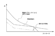
- the operating voltage of the electromagnet block 2 can be adjusted as follows. That is, the operating voltage of the electromagnet block 2 can be suppressed by changing the inclination angle of the elastic contact portion 46 of the hinge spring 44. Specifically, when the inclination angle of the elastic contact portion 46 with respect to the yoke 41 is increased, the magnetic field generated from the magnetic pole portion 25 of the iron core 22 acts on the attracted portion 63 of the movable iron piece 4 as shown in the graph of FIG. The position of the operating point can be changed with respect to a change in force (suction force curve).
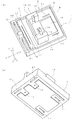
- FIG. 14 shows a configuration in which a connection member 77 is composed of a first connection portion 111 and a second connection portion 112, as in the case shown in FIG. 13.
- the second side walls 115a and 115b are different from each other in that the second side walls 115a and 115b are not bent half, but are bent at right angles from the intermediate walls 113a and 113b in the same manner as the first side walls 114a and 114b.
- the 1st connection part 111 and the 2nd connection part 112 are used in the state which made the intermediate
- a closed loop of the magnetic circuit can be formed at each of the two contact opening / closing positions, and magnetic flux leakage can be more effectively prevented.
- FIG. 16 shows a structure in which the intermediate projecting portion 137 is a flat plate integrally projecting from the central portion of the intermediate wall 133.
- the intermediate projecting portion 137 is formed by welding, bonding, or the like a plate material having the same shape as the opposing walls 134a, 134b to the central portion of the intermediate wall 133 with respect to a substantially U-shaped member including the intermediate wall 133 and the opposing walls 134a, 134b. Alternatively, it may be formed at the same time as the facing wall during press working. According to this configuration, unlike the above-described embodiments, there are no two members, no gaps and the like are generated, and the magnetic flux leakage is effectively prevented and the magnetic flux is concentrated at the contact opening / closing position. be able to.
Landscapes
- Physics & Mathematics (AREA)
- Electromagnetism (AREA)
- Arc-Extinguishing Devices That Are Switches (AREA)
Abstract
Description
接離可能な一対の接点からなる接点組を、少なくとも2組、接離方向とは直交する並設方向に配置してなる接点開閉部と、
前記接点開閉部を駆動して接点を開閉させる電磁石ブロックと、
前記全ての接点組に対して並設方向の両側と、前記各接点組の間とにそれぞれ突出する突出部を、中間部を介して互いに連続させてなる、磁性材料からなる接続部材と、少なくとも両側に位置する突出部の対向位置にそれぞれ設けた永久磁石とからなるアーク消弧部材と、
を備えたものである。
前記ケースは、前記アーク消弧部材の突出部及び永久磁石を配置可能な凹部を備えるのが好ましい。
前記接点は、前記ベースから突出する接触片の一端部に固定され、
前記アーク消弧部材は、前記接続部材の中間部を、前記接触片の突出方向側の接点近傍に配置するのが好ましい。
固定接触片と、この固定接触片に対向して配置した可動接触片とを有する接点開閉部を備え、電磁石ブロックを励磁・消磁して可動接触片を駆動し、この可動接触片に設けた可動接点を固定接触片に設けた固定接点に開閉するようにした電磁継電器であって、
前記固定接触片は、前記固定接点を有する、少なくとも2つで構成され、
前記可動接触片は、前記可動接点を有する、少なくとも一対の接触片部を備え、
前記各接触片部の両側と、各接点開閉位置の間とにそれぞれ突出する突出部を、中間部を介して互いに連続させた接続部材と、少なくとも両側に位置する突出部の対向位置にそれぞれ設けた永久磁石とからなるアーク消弧部材を設けたものである。
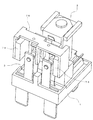
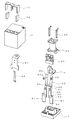
図1から図5は、本実施形態に係る電磁継電器を示す。この電磁継電器は、大略、ベース1に、電磁石ブロック2、接点開閉部3、及び、可動鉄片4を設け、ケース5を被せたものである。
ベース1は、図6に示すように、合成樹脂材料を成形加工することにより平面視矩形状に形成され、長手方向の2箇所には、第1装着部6と第2装着部7が設けられている(以下、長辺に沿って長手方向に延びる方向をX軸、短辺に沿って短手方向に延びる方向をY軸、高さ方向に延びる方向をZ軸として説明する)。
電磁石ブロック2は、図7及び図8に示すように、鉄心22にスプール23を介してコイル24を巻回したものである。
ヨーク41は、磁性材料を略L字形となるように折り曲げたものである。ヨーク41の一端部には、前記鉄心22の一端部を挿通して加締固定するための開口部41aが形成されている。ヨーク41の他端部は幅広となって、その下端部両側には突出部42がそれぞれ形成されている。両突出部42の間には、後述する可動鉄片4が位置し、一方の角部が可動鉄片4を回動可能に支持する支点として機能している。ヨーク41の中間部外面には、上下2箇所に加締用の突起43が形成されている。
接点開閉部3は、図4及び図5に示すように、銅等の導電性材料を板状にプレス加工した、固定接触片51と可動接触片52とで構成されている。
可動鉄片4は、図7及び図8に示すように、板状の磁性材料をプレス加工により略L字形に形成したものである。可動鉄片4の一端側は、鉄心22の磁極部25に吸引される被吸引部63である。被吸引部63の先端部及び基部は幅狭となっており、スプール23の底面に形成したガイド突部35と、ヨーク41の下端部に形成した突出部42との干渉がそれぞれ回避されている。可動鉄片4の他端側には開口部64が形成されている。開口部64にはヒンジバネ44が挿通し、被吸引部63の角部に圧接している。可動鉄片4の他端部は幅狭となっており、又、開口部64の上方側にはカード部材65が一体化されている。
ケース5は、図2に示すように、合成樹脂材料を下面が開口する箱状としたものである。ケース5の上面角部には密閉用孔71が形成されている。密閉用孔71は、ベース1とケース5の嵌合部分のシール後に熱封止される。ケース5の上面縁部(ガス抜き孔71と反対側)には、両側及び中央部にスリット状の凹部72がそれぞれ形成されている。各及ぶ72の間には、上面よりも窪んだ凹所73が形成されており、その上面中央部には突起74がそれぞれ形成されている。
続いて、前記構成からなる電磁継電器の組立方法について説明する。
次に、前記構成からなる電磁継電器の動作について説明する。
すなわち、ヒンジバネ44の弾性当接部46の傾斜角度を変更することにより、電磁石ブロック2の動作電圧を抑えることが可能となる。詳しくは、ヨーク41に対する弾性当接部46の傾斜角度を大きくすると、図12のグラフに示すように、鉄心22の磁極部25から発生させた磁界により可動鉄片4の被吸引部63に作用する力の変化(吸引力曲線)に対して、動作点の位置を変更することができる。つまり、弾性当接部46の傾斜角度を大きくすることにより、接点が開放してから第1突出部66に弾性当接部46が当接するまでの力を小さくして、そのときに必要となる力を抑えることができる。この結果、吸引力曲線が、図示されるものよりも小さい位置で変化するように、電磁石ブロック2の動作電圧を抑制することが可能となる。
なお、本発明は、前記実施形態に記載された構成に限定されるものではなく、種々の変更が可能である。
この構成によれば、前記実施形態に比べて磁束漏れをより一層効果的に防止することができ、永久磁石76にそれほど磁力の大きなものを使用しなくても、接点間に十分に磁束を集中させることが可能となる。
この構成によれば、2組の接点開閉位置のそれぞれで磁気回路の閉ループを形成することができ、磁束漏れをより一層効果的に防止することが可能となる。
この構成によれば、中間突出部127は前記実施形態のように両側部だけではなく、図13と同様に、ほぼ全面に中間突出部127を配置することができるようになっている。これにより、図13と同様に、磁束漏れを効果的に防止することが可能となる。
2…電磁石ブロック
3…接点開閉部
4…可動鉄片
5…ケース
6…第1装着部
7…第2装着部
8…第1周縁壁
9…凹所
10…支持凹部
11…コイル端子孔
12…ガイド部
13…ガイド壁
14…絶縁壁
15…ガイド溝
16…ガイド凹部
17…台座部
18…第1端子孔
19…連通部
20…第2周縁壁
21…第2端子孔
22…鉄心
23…スプール
24…コイル
25…磁極部
26…中心孔
27…胴部
28…上端側鍔部
29…下端側鍔部
30…逃がし溝
31…端子取付部
32…端子保持孔
33…段部
34…案内溝
35…ガイド突部
36…コイル端子
37…圧入部
38…幅広部
39…コイル巻付部
40…絶縁シート
41…ヨーク
42…突出部
43…突起
44…ヒンジバネ
45…接続部
46…弾性当接部
47…第1傾斜部
48…第2傾斜部
49…弾性支持部
50…被ガイド部
51…固定接触片
52…可動接触片
53…圧入部
54…端子部
55…接触片部
56…膨出部
57…固定接点
58…圧入部
59…接触片部
60…膨出部
61…突起
62…可動接点
63…被吸引部
64…開口部
65…カード部材
66…第1突出部
67…第2突出部
68…突条部
69…押圧部
70…遮蔽壁
71…密閉用孔
72…スリット
73…凹所
74…突起
75…アーク消弧部材
76…永久磁石
77…接続部材
78…対向壁
79…中間壁
80…中間突出部
101、111、121…第1接続部
102、112、122…第2接続部
103a、103b、113a、113b、123a、123b、133…中間壁
104a、104b、114a、114b、124a、124b…第1側壁
105a、105b、115a、115b、125a、125b…第2側壁
106a、106b…窪み部
107、117、127、137…中間突出部
134a、134b…対向壁
Claims (10)
- 接離可能な一対の接点からなる接点組を、少なくとも2組、接離方向とは直交する並設方向に配置してなる接点開閉部と、
前記接点開閉部を駆動して接点を開閉させる電磁石ブロックと、
前記全ての接点組に対して並設方向の両側と、前記各接点組の間とにそれぞれ突出する突出部を、中間部を介して互いに連続させてなる、磁性材料からなる接続部材と、少なくとも両側に位置する突出部の対向位置にそれぞれ設けた永久磁石とからなるアーク消弧部材と、
を備えたことを特徴とする電磁継電器。 - 前記ベースに取り付けられ、前記接点開閉部と前記電磁石ブロックとを覆うケースを備え、
前記ケースは、前記アーク消弧部材の突出部及び永久磁石を配置可能な凹部を備えたことを特徴とする請求項1に記載の電磁継電器。 - 前記各永久磁石の対向面の極性と、接点開閉時に発生するアーク電流が流れる方向とを、前記アーク電流に前記接続部材の中間部側へと変位する力を発生させることができるように決定したことを特徴とする請求項1又は2に記載の電磁継電器。
- 前記各永久磁石の対向面の極性と、接点開閉時に発生するアーク電流が流れる方向とを、隣接する接点開閉位置間で逆方向となるように決定したことを特徴とする請求項1又は2に記載の電磁継電器。
- 前記接点開閉部と前記電磁石ブロックとが取り付けられるベースを備え、
前記接点は、前記ベースから突出する接触片の一端部に固定され、
前記アーク消弧部材は、前記接続部材の中間部を、前記接触片の突出方向側の接点近傍に配置したことを特徴とする請求項1から4のいずれか1項に記載の電磁継電器。 - 固定接触片と、この固定接触片に対向して配置した可動接触片とを有する接点開閉部を備え、電磁石ブロックを励磁・消磁して可動接触片を駆動し、この可動接触片に設けた可動接点を固定接触片に設けた固定接点に開閉するようにした電磁継電器であって、
前記固定接触片は、前記固定接点を有する、少なくとも2つで構成され、
前記可動接触片は、前記可動接点を有する、少なくとも一対の接触片部を備え、
前記各接触片部の両側と、各接点開閉位置の間とにそれぞれ突出する突出部を、中間部を介して互いに連続させた接続部材と、少なくとも両側に位置する突出部の対向位置にそれぞれ設けた永久磁石とからなるアーク消弧部材を設けたことを特徴とする電磁継電器。 - 前記アーク消弧部材の接続部材は、中間壁の両端部に対向壁をそれぞれ形成し、中間壁の中央部に、両側部を中央部を挟んで反対側の対向壁側から曲げ起こすことにより、前記各接点組の間に位置する突出部を形成してなることを特徴とする請求項1から6のいずれか1項に記載の電磁継電器。
- 前記両突出部により平板状の壁面部を構成したことを特徴とする請求項7に記載の電磁継電器。
- 前記アーク消弧部材の接続部材は、第1接続部と第2接続部からなり、各接続部は、中間壁の両端部に第1側壁及び第2側壁をそれぞれ対向するように形成してなり、前記両第2側壁により、前記各接点組の間に位置する突出部を構成したことを特徴とする請求項1から6のいずれか1項に記載の電磁継電器。
- 前記第1接続部の第2側壁と、前記第2接続部の第2側壁とで平板状の壁面部を構成したことを特徴とする請求項9に記載の電磁継電器。
Priority Applications (4)
| Application Number | Priority Date | Filing Date | Title |
|---|---|---|---|
| US13/982,746 US9076617B2 (en) | 2011-03-14 | 2011-03-24 | Electromagnetic relay |
| KR1020137004080A KR101436269B1 (ko) | 2011-03-14 | 2011-03-24 | 전자 계전기 |
| EP11860969.2A EP2688084B1 (en) | 2011-03-14 | 2011-03-24 | Electromagnetic relay |
| CN201180066416.8A CN103403832B (zh) | 2011-03-14 | 2011-03-24 | 电磁继电器 |
Applications Claiming Priority (2)
| Application Number | Priority Date | Filing Date | Title |
|---|---|---|---|
| JP2011-055725 | 2011-03-14 | ||
| JP2011055725A JP5085754B2 (ja) | 2011-03-14 | 2011-03-14 | 電磁継電器 |
Publications (1)
| Publication Number | Publication Date |
|---|---|
| WO2012124164A1 true WO2012124164A1 (ja) | 2012-09-20 |
Family
ID=46830272
Family Applications (1)
| Application Number | Title | Priority Date | Filing Date |
|---|---|---|---|
| PCT/JP2011/057131 Ceased WO2012124164A1 (ja) | 2011-03-14 | 2011-03-24 | 電磁継電器 |
Country Status (6)
| Country | Link |
|---|---|
| US (1) | US9076617B2 (ja) |
| EP (1) | EP2688084B1 (ja) |
| JP (1) | JP5085754B2 (ja) |
| KR (1) | KR101436269B1 (ja) |
| CN (1) | CN103403832B (ja) |
| WO (1) | WO2012124164A1 (ja) |
Cited By (4)
| Publication number | Priority date | Publication date | Assignee | Title |
|---|---|---|---|---|
| EP2768004A1 (en) * | 2013-02-13 | 2014-08-20 | Omron Corporation | Electromagnetic relay |
| EP2741307A3 (en) * | 2012-12-07 | 2015-06-17 | Fujitsu Component Limited | Electromagnetic Relay |
| CN112154527A (zh) * | 2018-05-23 | 2020-12-29 | 松下知识产权经营株式会社 | 触点装置和电磁继电器 |
| WO2024185487A1 (ja) * | 2023-03-08 | 2024-09-12 | オムロン株式会社 | 電磁継電器 |
Families Citing this family (26)
| Publication number | Priority date | Publication date | Assignee | Title |
|---|---|---|---|---|
| JP5085754B2 (ja) | 2011-03-14 | 2012-11-28 | オムロン株式会社 | 電磁継電器 |
| DE202013102019U1 (de) * | 2013-05-08 | 2014-08-11 | Eto Magnetic Gmbh | Elektromagnetische Stellvorrichtung |
| DE102013210195A1 (de) * | 2013-05-31 | 2014-12-04 | Tyco Electronics Amp Gmbh | Anordnung für ein elektrisches Schaltelement und Schaltelement |
| JP6406596B2 (ja) * | 2014-05-12 | 2018-10-17 | パナソニックIpマネジメント株式会社 | 接点装置 |
| JP6433706B2 (ja) * | 2014-07-28 | 2018-12-05 | 富士通コンポーネント株式会社 | 電磁継電器及びコイル端子 |
| EP2996137B1 (en) * | 2014-09-10 | 2019-05-08 | Tyco Electronics EC Trutnov s.r.o. | Yoke assembly with deceleration element for switching device and same |
| US9728347B2 (en) * | 2014-12-16 | 2017-08-08 | Hamilton Sundstrand Corporation | Integrated contactor mounting and power distribution system and method |
| JP6447919B2 (ja) * | 2015-04-07 | 2019-01-09 | パナソニックIpマネジメント株式会社 | 電磁継電器 |
| KR101943363B1 (ko) * | 2015-04-13 | 2019-04-17 | 엘에스산전 주식회사 | 전자개폐기 |
| KR101922155B1 (ko) | 2015-09-03 | 2018-11-27 | 현대일렉트릭앤에너지시스템(주) | 전자접촉기 |
| JP6657692B2 (ja) * | 2015-09-11 | 2020-03-04 | オムロン株式会社 | 電磁石装置およびこれを用いた電磁継電器 |
| JP6981732B2 (ja) | 2015-09-28 | 2021-12-17 | 富士通コンポーネント株式会社 | 電磁継電器 |
| JP2018006209A (ja) * | 2016-07-05 | 2018-01-11 | 富士通コンポーネント株式会社 | 電磁継電器 |
| JP6836241B2 (ja) * | 2016-12-27 | 2021-02-24 | 富士通コンポーネント株式会社 | 電磁継電器 |
| CN110970266A (zh) * | 2018-09-30 | 2020-04-07 | 泰科电子(深圳)有限公司 | 电磁继电器 |
| CN110970268A (zh) * | 2018-09-30 | 2020-04-07 | 泰科电子(深圳)有限公司 | 电磁继电器 |
| CN109243923B (zh) * | 2018-11-14 | 2024-07-16 | 厦门普利得汽车电子有限公司 | 高压直流继电器 |
| TWI692793B (zh) * | 2019-01-19 | 2020-05-01 | 百容電子股份有限公司 | 電磁繼電器 |
| JP7287225B2 (ja) * | 2019-09-30 | 2023-06-06 | オムロン株式会社 | リレー |
| JP7505213B2 (ja) * | 2020-03-13 | 2024-06-25 | オムロン株式会社 | 電磁継電器 |
| CN111863538A (zh) * | 2020-06-24 | 2020-10-30 | 华为技术有限公司 | 一种直流接触器及车辆 |
| JP7521446B2 (ja) * | 2021-02-03 | 2024-07-24 | オムロン株式会社 | タブ端子を備えるパワーリレー |
| CN114093696B (zh) * | 2021-09-29 | 2025-10-10 | 漳州宏发电声有限公司 | 一种带灭弧磁钢的磁保持继电器 |
| JP7711548B2 (ja) * | 2021-10-19 | 2025-07-23 | オムロン株式会社 | 電磁継電器 |
| JP7718221B2 (ja) * | 2021-10-19 | 2025-08-05 | オムロン株式会社 | 電磁継電器 |
| CN119208106B (zh) * | 2024-11-25 | 2025-04-01 | 佛山市九龙机器有限公司 | 一种带磁吹及多重保护的限温器 |
Citations (5)
| Publication number | Priority date | Publication date | Assignee | Title |
|---|---|---|---|---|
| JPS5511064U (ja) * | 1978-06-30 | 1980-01-24 | ||
| JPS5534346U (ja) * | 1978-08-28 | 1980-03-05 | ||
| JPS60107551U (ja) * | 1983-12-26 | 1985-07-22 | オムロン株式会社 | 電磁継電器 |
| JP2001176370A (ja) * | 1999-12-16 | 2001-06-29 | Denso Corp | 電磁継電器 |
| JP2007305466A (ja) * | 2006-05-12 | 2007-11-22 | Omron Corp | 電磁継電器 |
Family Cites Families (58)
| Publication number | Priority date | Publication date | Assignee | Title |
|---|---|---|---|---|
| US2735968A (en) * | 1956-02-21 | Relay structure | ||
| US2875304A (en) * | 1956-03-30 | 1959-02-24 | Westinghouse Electric Corp | Circuit interrupter |
| JPS538901B2 (ja) * | 1971-09-01 | 1978-04-01 | ||
| JPS5511064A (en) | 1978-07-12 | 1980-01-25 | Toyota Motor Corp | Rotary type electrostatic coater for conductive paint |
| JPS5927980B2 (ja) | 1978-08-31 | 1984-07-10 | 富士通株式会社 | 不良テ−プの検出装置 |
| DE2912800C2 (de) * | 1979-03-30 | 1985-04-25 | Siemens AG, 1000 Berlin und 8000 München | Elektromagnetisches Relais für hohe Schaltleistungen |
| NZ194794A (en) * | 1979-09-10 | 1983-05-31 | Westinghouse Electric Corp | Switchgear permanent magnets create arc blowout field |
| JPS5713628A (en) * | 1980-06-27 | 1982-01-23 | Mitsubishi Electric Corp | Direct current electromagnetic contactor |
| JPS60107551A (ja) | 1983-11-15 | 1985-06-13 | Furukawa Electric Co Ltd:The | 光フアイバ母材の組成分析方法 |
| DE8438436U1 (de) * | 1984-04-18 | 1987-10-22 | Hengstler Bauelemente GmbH, 7209 Wehingen | Kleinstrelais |
| EP0483121B1 (en) * | 1986-06-06 | 1994-09-07 | Mitsubishi Denki Kabushiki Kaisha | Switchgear |
| JPS63149039U (ja) * | 1987-03-20 | 1988-09-30 | ||
| US4761627A (en) * | 1987-09-17 | 1988-08-02 | Potter And Brumfield Inc. | Electromagnetic relay including a rotatable armature mount |
| US4758809A (en) * | 1987-09-17 | 1988-07-19 | Potter And Brumfield Inc. | Electromagnetic relay having a multifunction retaining spring |
| JP2658170B2 (ja) * | 1988-05-11 | 1997-09-30 | オムロン株式会社 | 開閉器 |
| DE3835118A1 (de) * | 1988-10-14 | 1990-04-19 | Siemens Ag | Elektromagnetisches relais |
| EP0372554A3 (en) * | 1988-12-09 | 1992-04-08 | OMRON Corporation | Electromagnetic relay |
| JPH0346728A (ja) * | 1989-07-13 | 1991-02-28 | Omron Corp | 電磁継電器 |
| JPH0469836U (ja) * | 1990-10-26 | 1992-06-19 | ||
| EP0501070B2 (en) * | 1991-02-27 | 2003-05-14 | Takamisawa Electric Co., Ltd. | Small sized electromagnetic relay |
| EP0579832B1 (en) * | 1991-04-09 | 1999-10-06 | Omron Corporation | Electromagnetic relay |
| JP2767331B2 (ja) | 1991-09-30 | 1998-06-18 | 東芝硝子株式会社 | ガラス成形装置 |
| JP3383984B2 (ja) * | 1992-05-14 | 2003-03-10 | オムロン株式会社 | 電磁継電器 |
| JPH0652761A (ja) * | 1992-08-01 | 1994-02-25 | Mitsubishi Electric Corp | 開閉器 |
| US5289144A (en) * | 1992-08-21 | 1994-02-22 | Potter & Brumfield, Inc. | Electromagnetic relay and method for assembling the same |
| DE4300594A1 (de) * | 1993-01-13 | 1994-07-14 | Hengstler Bauelemente | Sicherheitsrelais mit zwangsgeführtem Kontaktsatz und monostabilem Antrieb |
| US5321377A (en) * | 1993-01-21 | 1994-06-14 | Kaloust P. Sagoian | Electromagnet for relays and contactor assemblies |
| DE4405222C1 (de) * | 1994-02-18 | 1995-05-11 | Siemens Ag | Verfahren zur Herstellung eines Relais mit beweglichem Schieber und nach dem Verfahren hergestelltes Relais |
| JP3321963B2 (ja) * | 1994-02-22 | 2002-09-09 | 株式会社デンソー | プランジャ型電磁継電器 |
| JPH07254340A (ja) * | 1994-03-15 | 1995-10-03 | Omron Corp | 電磁継電器 |
| IT233985Y1 (it) * | 1994-07-29 | 2000-02-16 | Gavazzi Carlo Electromatic | Rele' elettromagnetico pluricontatto miniatura per usi industriali |
| ATE170663T1 (de) * | 1995-03-21 | 1998-09-15 | Siemens Ag | Elektromagnetisches relais |
| US5805040A (en) * | 1996-09-27 | 1998-09-08 | Simens Electromechanical Components, Inc. | Relay base and method of assembly |
| JP3713850B2 (ja) * | 1996-11-25 | 2005-11-09 | 松下電工株式会社 | 直流開閉器 |
| DE19804572A1 (de) * | 1997-05-05 | 1999-08-12 | Schrack Components Ag | Relais mit Kontaktfedern |
| DE19727991C1 (de) * | 1997-07-01 | 1998-11-19 | Schrack Components Ag | Elektromagnetisches Relais |
| EP0938119A1 (de) * | 1998-02-18 | 1999-08-25 | ELESTA relays GmbH | Relais |
| US6486760B2 (en) * | 1998-12-07 | 2002-11-26 | Matsushita Electric Works, Ltd. | Electromagnetic relay |
| EP1168392B1 (en) * | 1999-10-14 | 2005-05-04 | Matsushita Electric Works, Ltd. | Contactor |
| JP4212248B2 (ja) * | 2001-02-09 | 2009-01-21 | 富士通コンポーネント株式会社 | 電磁継電器 |
| JP4334158B2 (ja) * | 2001-03-26 | 2009-09-30 | 富士通コンポーネント株式会社 | 電磁継電器 |
| US6798322B2 (en) * | 2002-06-17 | 2004-09-28 | Tyco Electronics Corporation | Low noise relay |
| JP4131161B2 (ja) * | 2002-11-12 | 2008-08-13 | オムロン株式会社 | 電磁継電器 |
| JP2004311389A (ja) * | 2003-02-21 | 2004-11-04 | Sumitomo Electric Ind Ltd | 直流リレー |
| JP4190379B2 (ja) * | 2003-09-12 | 2008-12-03 | 富士通コンポーネント株式会社 | 複合型電磁継電器 |
| JP4424260B2 (ja) * | 2005-06-07 | 2010-03-03 | オムロン株式会社 | 電磁リレー |
| JP4810937B2 (ja) * | 2005-09-06 | 2011-11-09 | オムロン株式会社 | 開閉装置 |
| JP4742954B2 (ja) * | 2006-03-31 | 2011-08-10 | オムロン株式会社 | 電磁継電器 |
| US7477119B2 (en) * | 2007-03-02 | 2009-01-13 | Good Sky Electric Co., Ltd. | Electromagnetic relay |
| JP4946559B2 (ja) * | 2007-03-22 | 2012-06-06 | オムロン株式会社 | 電磁継電器 |
| JP5058643B2 (ja) * | 2007-03-26 | 2012-10-24 | 富士通コンポーネント株式会社 | 電磁継電器 |
| US8193881B2 (en) * | 2007-09-14 | 2012-06-05 | Fujitsu Component Limited | Relay |
| JP5202072B2 (ja) * | 2007-09-14 | 2013-06-05 | 富士通コンポーネント株式会社 | リレー |
| JP5163318B2 (ja) * | 2008-06-30 | 2013-03-13 | オムロン株式会社 | 電磁石装置 |
| TW201019364A (en) * | 2008-11-12 | 2010-05-16 | Good Sky Electric Co Ltd | An electromagnetic relay |
| JP2012038684A (ja) * | 2010-08-11 | 2012-02-23 | Fuji Electric Fa Components & Systems Co Ltd | 接点装置及びこれを使用した電磁開閉器 |
| JP5085754B2 (ja) | 2011-03-14 | 2012-11-28 | オムロン株式会社 | 電磁継電器 |
| JP5923932B2 (ja) * | 2011-11-04 | 2016-05-25 | オムロン株式会社 | 接点開閉機構及び電磁継電器 |
-
2011
- 2011-03-14 JP JP2011055725A patent/JP5085754B2/ja active Active
- 2011-03-24 EP EP11860969.2A patent/EP2688084B1/en active Active
- 2011-03-24 CN CN201180066416.8A patent/CN103403832B/zh active Active
- 2011-03-24 KR KR1020137004080A patent/KR101436269B1/ko active Active
- 2011-03-24 US US13/982,746 patent/US9076617B2/en active Active
- 2011-03-24 WO PCT/JP2011/057131 patent/WO2012124164A1/ja not_active Ceased
Patent Citations (5)
| Publication number | Priority date | Publication date | Assignee | Title |
|---|---|---|---|---|
| JPS5511064U (ja) * | 1978-06-30 | 1980-01-24 | ||
| JPS5534346U (ja) * | 1978-08-28 | 1980-03-05 | ||
| JPS60107551U (ja) * | 1983-12-26 | 1985-07-22 | オムロン株式会社 | 電磁継電器 |
| JP2001176370A (ja) * | 1999-12-16 | 2001-06-29 | Denso Corp | 電磁継電器 |
| JP2007305466A (ja) * | 2006-05-12 | 2007-11-22 | Omron Corp | 電磁継電器 |
Cited By (5)
| Publication number | Priority date | Publication date | Assignee | Title |
|---|---|---|---|---|
| EP2741307A3 (en) * | 2012-12-07 | 2015-06-17 | Fujitsu Component Limited | Electromagnetic Relay |
| EP2768004A1 (en) * | 2013-02-13 | 2014-08-20 | Omron Corporation | Electromagnetic relay |
| US8928438B2 (en) | 2013-02-13 | 2015-01-06 | Omron Corporation | Electromagnetic relay |
| CN112154527A (zh) * | 2018-05-23 | 2020-12-29 | 松下知识产权经营株式会社 | 触点装置和电磁继电器 |
| WO2024185487A1 (ja) * | 2023-03-08 | 2024-09-12 | オムロン株式会社 | 電磁継電器 |
Also Published As
| Publication number | Publication date |
|---|---|
| EP2688084A1 (en) | 2014-01-22 |
| KR101436269B1 (ko) | 2014-08-29 |
| JP2012190764A (ja) | 2012-10-04 |
| KR20130041219A (ko) | 2013-04-24 |
| EP2688084A4 (en) | 2014-11-05 |
| JP5085754B2 (ja) | 2012-11-28 |
| CN103403832B (zh) | 2017-03-01 |
| US9076617B2 (en) | 2015-07-07 |
| CN103403832A (zh) | 2013-11-20 |
| EP2688084B1 (en) | 2019-04-10 |
| US20140028418A1 (en) | 2014-01-30 |
Similar Documents
| Publication | Publication Date | Title |
|---|---|---|
| JP5085754B2 (ja) | 電磁継電器 | |
| JP4883232B1 (ja) | 電磁継電器 | |
| JP5923932B2 (ja) | 接点開閉機構及び電磁継電器 | |
| JP5741338B2 (ja) | 端子部材のシール構造、及び、電磁継電器 | |
| KR101435349B1 (ko) | 전자 계전기 | |
| JP5085755B2 (ja) | 電磁継電器 | |
| JP2007073308A (ja) | 開閉装置 | |
| JP2014044837A (ja) | 電磁石装置およびそれを用いた電磁継電器 | |
| JP2005166431A (ja) | 電磁継電器 | |
| JP4586861B2 (ja) | 電磁継電器 | |
| JP2012212668A (ja) | 接点装置及び電磁開閉器 | |
| JP2005183097A (ja) | 電磁リレー | |
| JP2005166433A (ja) | 電磁継電器 |
Legal Events
| Date | Code | Title | Description |
|---|---|---|---|
| 121 | Ep: the epo has been informed by wipo that ep was designated in this application |
Ref document number: 11860969 Country of ref document: EP Kind code of ref document: A1 |
|
| ENP | Entry into the national phase |
Ref document number: 20137004080 Country of ref document: KR Kind code of ref document: A |
|
| WWE | Wipo information: entry into national phase |
Ref document number: 2011860969 Country of ref document: EP |
|
| NENP | Non-entry into the national phase |
Ref country code: DE |
|
| WWE | Wipo information: entry into national phase |
Ref document number: 13982746 Country of ref document: US |