WO2012124246A1 - Procédé de production de couche mince et dispositif de production de couche mince - Google Patents
Procédé de production de couche mince et dispositif de production de couche mince Download PDFInfo
- Publication number
- WO2012124246A1 WO2012124246A1 PCT/JP2012/000400 JP2012000400W WO2012124246A1 WO 2012124246 A1 WO2012124246 A1 WO 2012124246A1 JP 2012000400 W JP2012000400 W JP 2012000400W WO 2012124246 A1 WO2012124246 A1 WO 2012124246A1
- Authority
- WO
- WIPO (PCT)
- Prior art keywords
- substrate
- thin film
- cooling material
- main surface
- formation region
- Prior art date
- Legal status (The legal status is an assumption and is not a legal conclusion. Google has not performed a legal analysis and makes no representation as to the accuracy of the status listed.)
- Ceased
Links
Images


Classifications
-
- H—ELECTRICITY
- H01—ELECTRIC ELEMENTS
- H01M—PROCESSES OR MEANS, e.g. BATTERIES, FOR THE DIRECT CONVERSION OF CHEMICAL ENERGY INTO ELECTRICAL ENERGY
- H01M4/00—Electrodes
- H01M4/02—Electrodes composed of, or comprising, active material
- H01M4/04—Processes of manufacture in general
- H01M4/0402—Methods of deposition of the material
- H01M4/0421—Methods of deposition of the material involving vapour deposition
- H01M4/0423—Physical vapour deposition
- H01M4/0426—Sputtering
-
- C—CHEMISTRY; METALLURGY
- C23—COATING METALLIC MATERIAL; COATING MATERIAL WITH METALLIC MATERIAL; CHEMICAL SURFACE TREATMENT; DIFFUSION TREATMENT OF METALLIC MATERIAL; COATING BY VACUUM EVAPORATION, BY SPUTTERING, BY ION IMPLANTATION OR BY CHEMICAL VAPOUR DEPOSITION, IN GENERAL; INHIBITING CORROSION OF METALLIC MATERIAL OR INCRUSTATION IN GENERAL
- C23C—COATING METALLIC MATERIAL; COATING MATERIAL WITH METALLIC MATERIAL; SURFACE TREATMENT OF METALLIC MATERIAL BY DIFFUSION INTO THE SURFACE, BY CHEMICAL CONVERSION OR SUBSTITUTION; COATING BY VACUUM EVAPORATION, BY SPUTTERING, BY ION IMPLANTATION OR BY CHEMICAL VAPOUR DEPOSITION, IN GENERAL
- C23C14/00—Coating by vacuum evaporation, by sputtering or by ion implantation of the coating forming material
- C23C14/22—Coating by vacuum evaporation, by sputtering or by ion implantation of the coating forming material characterised by the process of coating
- C23C14/24—Vacuum evaporation
-
- C—CHEMISTRY; METALLURGY
- C23—COATING METALLIC MATERIAL; COATING MATERIAL WITH METALLIC MATERIAL; CHEMICAL SURFACE TREATMENT; DIFFUSION TREATMENT OF METALLIC MATERIAL; COATING BY VACUUM EVAPORATION, BY SPUTTERING, BY ION IMPLANTATION OR BY CHEMICAL VAPOUR DEPOSITION, IN GENERAL; INHIBITING CORROSION OF METALLIC MATERIAL OR INCRUSTATION IN GENERAL
- C23C—COATING METALLIC MATERIAL; COATING MATERIAL WITH METALLIC MATERIAL; SURFACE TREATMENT OF METALLIC MATERIAL BY DIFFUSION INTO THE SURFACE, BY CHEMICAL CONVERSION OR SUBSTITUTION; COATING BY VACUUM EVAPORATION, BY SPUTTERING, BY ION IMPLANTATION OR BY CHEMICAL VAPOUR DEPOSITION, IN GENERAL
- C23C14/00—Coating by vacuum evaporation, by sputtering or by ion implantation of the coating forming material
- C23C14/22—Coating by vacuum evaporation, by sputtering or by ion implantation of the coating forming material characterised by the process of coating
- C23C14/54—Controlling or regulating the coating process
- C23C14/541—Heating or cooling of the substrates
-
- C—CHEMISTRY; METALLURGY
- C23—COATING METALLIC MATERIAL; COATING MATERIAL WITH METALLIC MATERIAL; CHEMICAL SURFACE TREATMENT; DIFFUSION TREATMENT OF METALLIC MATERIAL; COATING BY VACUUM EVAPORATION, BY SPUTTERING, BY ION IMPLANTATION OR BY CHEMICAL VAPOUR DEPOSITION, IN GENERAL; INHIBITING CORROSION OF METALLIC MATERIAL OR INCRUSTATION IN GENERAL
- C23C—COATING METALLIC MATERIAL; COATING MATERIAL WITH METALLIC MATERIAL; SURFACE TREATMENT OF METALLIC MATERIAL BY DIFFUSION INTO THE SURFACE, BY CHEMICAL CONVERSION OR SUBSTITUTION; COATING BY VACUUM EVAPORATION, BY SPUTTERING, BY ION IMPLANTATION OR BY CHEMICAL VAPOUR DEPOSITION, IN GENERAL
- C23C14/00—Coating by vacuum evaporation, by sputtering or by ion implantation of the coating forming material
- C23C14/22—Coating by vacuum evaporation, by sputtering or by ion implantation of the coating forming material characterised by the process of coating
- C23C14/56—Apparatus specially adapted for continuous coating; Arrangements for maintaining the vacuum, e.g. vacuum locks
- C23C14/562—Apparatus specially adapted for continuous coating; Arrangements for maintaining the vacuum, e.g. vacuum locks for coating elongated substrates
-
- H—ELECTRICITY
- H01—ELECTRIC ELEMENTS
- H01M—PROCESSES OR MEANS, e.g. BATTERIES, FOR THE DIRECT CONVERSION OF CHEMICAL ENERGY INTO ELECTRICAL ENERGY
- H01M4/00—Electrodes
- H01M4/02—Electrodes composed of, or comprising, active material
- H01M4/13—Electrodes for accumulators with non-aqueous electrolyte, e.g. for lithium-accumulators; Processes of manufacture thereof
- H01M4/139—Processes of manufacture
- H01M4/1395—Processes of manufacture of electrodes based on metals, Si or alloys
-
- Y—GENERAL TAGGING OF NEW TECHNOLOGICAL DEVELOPMENTS; GENERAL TAGGING OF CROSS-SECTIONAL TECHNOLOGIES SPANNING OVER SEVERAL SECTIONS OF THE IPC; TECHNICAL SUBJECTS COVERED BY FORMER USPC CROSS-REFERENCE ART COLLECTIONS [XRACs] AND DIGESTS
- Y02—TECHNOLOGIES OR APPLICATIONS FOR MITIGATION OR ADAPTATION AGAINST CLIMATE CHANGE
- Y02E—REDUCTION OF GREENHOUSE GAS [GHG] EMISSIONS, RELATED TO ENERGY GENERATION, TRANSMISSION OR DISTRIBUTION
- Y02E60/00—Enabling technologies; Technologies with a potential or indirect contribution to GHG emissions mitigation
- Y02E60/10—Energy storage using batteries
Definitions
- the present invention relates to a thin film manufacturing method and manufacturing apparatus.
- Thin film technology is widely deployed to improve the performance and miniaturization of devices.
- the thinning of devices is not only a direct merit for users, but also plays an important role in environmental aspects such as protecting earth resources and reducing power consumption.
- the winding-type thin film manufacturing method is a method in which a long substrate is unwound from a winding roller, a thin film is formed on the substrate while being transported along the transport path, and then the substrate is wound on the winding roller. .
- a thin film can be formed with high productivity by combining a film formation source having a high deposition rate such as a vacuum evaporation source using an electron beam with a winding thin film manufacturing method. Further, when a thin film is continuously formed on each of the plate-like discrete substrates, a large number of stacked substrates are sequentially sent out from the delivery stocker to the film formation region. After film formation, the substrates are sequentially stored in a collection stocker.
- a film formation source having a high deposition rate such as a vacuum evaporation source using an electron beam with a winding thin film manufacturing method.
- the substrate can be cooled by a cylindrical can. Specifically, a thin film is formed on a substrate running along a cylindrical can. If the thermal contact between the substrate and the cylindrical can is ensured, heat can be released to the cylindrical can having a large heat capacity, so that an increase in the temperature of the substrate can be prevented. Further, the temperature of the substrate can be maintained at a specific cooling temperature. The cooling of the substrate by the cylindrical can is also effective in the transfer path other than the film formation region. In order to improve the adhesion between the cylindrical can and the substrate, the attachment of the substrate to the cylindrical can may be strengthened using an electron beam.
- Patent Document 1 discloses that in an apparatus for forming a thin film on a web that is a substrate, a gas is introduced into a region between the web and a support means. According to this method, since heat conduction between the web and the support means can be ensured, an increase in the temperature of the web can be suppressed.
- Patent Document 2 discloses a method of cooling a cylindrical can by making the inside of a cylindrical cooling part of the cylindrical can an independent decompression system and evaporating the refrigerant along the inner wall surface of the cylindrical cooling part.
- Patent Document 3 discloses a belt cooling method when a belt is used for transporting and cooling a substrate material. According to this method, in order to further cool the cooling belt, a cooling mechanism using a double or more cooling belt or a liquid medium is provided inside. Thereby, since the cooling efficiency can be increased, the characteristics of the magnetic tape including the electromagnetic conversion characteristics can be improved, and at the same time, the productivity can be greatly improved.
- substrate can be made to contact a support block. In order to improve heat conduction between the support block and the substrate, it is effective to introduce a gas between the substrate and the support block.
- JP-A-1-152262 Japanese Patent Publication No. 3-59987 JP-A-6-145982
- An object of the present invention is to solve the above-described conventional problems, and to provide a thin film manufacturing method and a manufacturing apparatus capable of achieving a high substrate cooling capability while suppressing deterioration of the degree of vacuum.
- the present invention Forming a thin film on the first main surface of the substrate in a vacuum; Prior to the thin film formation step, a step of applying a substrate cooling material that can be evaporated by heat applied to the substrate when forming the thin film to the second main surface of the substrate; A method for producing a thin film is provided.
- the present invention provides: A vacuum chamber; A film-forming source disposed in the vacuum chamber and forming a thin film on the first main surface of the substrate in a film-forming region in the vacuum chamber; A transport system that is disposed in the vacuum chamber and transports the substrate from a delivery position to a recovery position along a transport path set so that the substrate passes through the film formation region; A coater for applying to the second main surface of the substrate a substrate cooling material that can be evaporated by heat applied to the substrate when forming the thin film; An apparatus for manufacturing a thin film is provided.
- the substrate can be cooled by the heat of vaporization of the substrate cooling material applied to the second main surface. Since the vaporization heat of the substrate cooling material is used, more heat can be taken from the substrate with a small amount of the substrate cooling material than in the case of direct cooling with gas. Therefore, according to the present invention, a high cooling capacity can be achieved while suppressing the deterioration of the degree of vacuum.
- the present invention does not exclude the use of conventional gas cooling. It is also possible to use the present invention in combination with gas cooling.
- main surface means a surface having the widest area.
- first main surface corresponds to the front surface of the substrate
- second main surface corresponds to the back surface of the substrate.
- FIG. 1 Schematic of a thin film manufacturing apparatus according to an embodiment of the present invention. Partial enlarged view of FIG. The figure which shows the method of providing a substrate cooling material to the linear part of a substrate Figure showing another example of evaporation source
- Schematic of thin film manufacturing apparatus according to Modification 1 Schematic of thin film manufacturing apparatus according to Modification 2
- Schematic of thin film manufacturing apparatus according to Modification 3 Schematic of thin film manufacturing apparatus according to Modification 4
- Partial enlarged view of FIG. Schematic of thin film manufacturing apparatus according to Modification 5
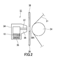
- the thin film manufacturing apparatus 100A includes a vacuum chamber 22, a transport system 40, an evaporation source 9 (film formation source), and a coater 11 (coater).
- the evaporation source 9, the transport system 40 and the coater 11 are disposed inside the vacuum chamber 22.
- the substrate cooling material 10 is applied to the second main surface of the substrate 21 by the coater 11.
- the substrate cooling material 10 is evaporated by heat applied to the substrate 21 when a thin film is formed on the substrate 21.
- the substrate 21 is cooled by the heat of vaporization of the substrate cooling material 10. Thereby, it is possible to prevent the substrate 21 from being damaged by heat.
- the vacuum chamber 22 is composed of a pressure-resistant container.
- a vacuum pump 32 is connected to the vacuum chamber 22.
- a shielding plate 29, an electron gun 19, and a source gas introduction pipe 30 are provided inside the vacuum chamber 22.
- the inside of the vacuum chamber 22 is partitioned by a shielding plate 29 into a region where the evaporation source 9 is disposed and a region where the transport system 40 is disposed.
- the shielding plate 29 has an opening for forming the film formation region 31 on the transport path of the substrate 21. When the substrate 21 passes through the film formation region 31, raw material particles flying from the evaporation source 9 are deposited on the substrate 21.
- the transport system 40 forms a transport path for the substrate 21 in the vacuum chamber 22 and plays a role of transporting the substrate 21 from the delivery position to the collection position along the transport path.
- the transport path is set so that the substrate 21 passes through the film formation region 31. Specifically, the transport path is set so that the substrate 21 travels linearly in the film formation region 31. In the film formation region 31, the raw material particles from the evaporation source 9 enter the substrate 21 substantially perpendicularly.
- the transport system 40 is constituted by an unwind roller 23, a transport roller 24, and a take-up roller 26.
- a substrate 21 before film formation is prepared on the unwinding roller 23.
- the unwinding roller 23 supplies the substrate 21 toward the transport roller 24 disposed closest to the unwinding roller 23.
- the transport roller 24 disposed upstream in the transport direction of the substrate 21 guides the substrate 21 supplied from the unwinding roller 23 to the film formation region 31.
- the transport roller 24 disposed downstream in the transport direction guides the substrate 21 to the take-up roller 26.
- the take-up roller 26 is driven by a driving means (not shown) such as a motor, and takes up and stores the substrate 21 after film formation.
- the unwinding roller 23 and the take-up roller 26 constitute a sending position and a collecting position for the substrate 21, respectively.
- the evaporation source 9 is used to form a thin film on the first main surface of the substrate 21 in the film formation region 31.
- the evaporation source 9 includes a crucible that holds a thin film material, and is provided below the film formation region 31.
- the raw material held in the evaporation source 9 is heated and evaporated.
- the raw material vapor moves upward and adheres to the substrate 21 in the film formation region 31. As a result, a thin film is formed on the substrate 21.
- a raw material supply machine for adding a raw material to the evaporation source 9 without purging the vacuum may be provided inside the vacuum chamber 22.
- the form of the raw material to be supplied is not particularly limited.
- a raw material melt generated by melting a rod-shaped raw material can be supplied to the evaporation source 9 in the form of droplets. This method is preferable because the temperature change of the melt held in the evaporation source 9 can be suppressed and the evaporation rate of the raw material hardly fluctuates.
- An electron beam can be used to melt the rod-shaped raw material.
- the thin-film manufacturing apparatus 100A can be simplified, so that a reduction in cost can be expected.
- Both the straight gun and the deflection gun can be used as the electron gun 19.
- a straight gun having a high output and a wide scanning range of the electron beam.
- it is effective to bend the trajectory of the electron beam about several degrees from the viewpoint of preventing contamination inside the barrel of the electron gun 19.
- a rectangular crucible having an opening width wider than the film forming width can be used as the evaporation source 9 in continuous vacuum deposition represented by a winding type. Such a crucible is effective from the viewpoint of ensuring film thickness uniformity in the width direction of the substrate 21.
- the irradiation position of the electron beam for melting the rod-shaped raw material and the dropping position of the molten raw material on the evaporation source 9 are outside the scanning range of the electron beam for evaporating the melt held in the evaporation source 9. Can be set. If it does in this way, the temperature change of the melt by adding a raw material and the vibration of the surface of a melt can be controlled. That is, the influence on the film forming conditions can be reduced. Control of the irradiation position of the electron beam is achieved by using an electron beam scanning circuit provided in the electron gun system and finely controlling a coil current for generating a magnetic field.
- the source gas introduction pipe 30 has one end directed to the space inside the vacuum chamber 22 and the other end extending to the outside of the vacuum chamber 22.
- One end of the source gas introduction pipe 30 is directed, for example, to a space between the evaporation source 9 and the film formation region 31.
- the other end of the source gas introduction pipe 30 is connected to a source gas supply source such as a gas cylinder or a gas generator outside the vacuum chamber 22. If the source gas introduction pipe 30 is used, a gas such as oxygen or nitrogen can be mixed with the source material evaporated from the evaporation source 9. As a result, a thin film containing a raw material oxide, nitride or oxynitride as a main component evaporated from the evaporation source 9 is formed on the substrate 21.
- the vacuum pump 32 is connected to the vacuum chamber 22.
- various vacuum pumps such as a rotary pump, an oil diffusion pump, a cryopump, and a turbo molecular pump can be used.
- the coater 11 is used to apply the substrate cooling material 10 to the second main surface of the substrate 21, that is, the surface opposite to the surface on which the thin film is to be formed.
- the position of the coater 11 is such that the substrate cooling material 10 is applied to the second main surface of the substrate 21 on the transport path between the unwinding roller 23 (delivery position) and the film formation region 31. Is set. If the substrate cooling material 10 is applied to the substrate 21 immediately before the film formation, it is possible to prevent the substrate cooling material 10 from detaching from the substrate 21 before reaching the film formation region 31 as much as possible.
- the coater 11 is configured to deposit the substrate cooling material 10 on the second main surface of the substrate 21. According to the vapor deposition method, the substrate cooling material 10 can be applied to the substrate 21 with a uniform and minimum necessary thickness relatively easily.
- the coater 11 includes a container 34, a heater 35, and a nozzle 36.
- the container 34 holds the substrate cooling material 10.
- the heater 35 heats the substrate cooling material 10 held in the container 34.
- the nozzle 36 is provided with a discharge port 37 (slit) extending from the inside of the container 34 toward the second main surface of the substrate 21.
- the width (inner diameter) of the discharge port 37 is, for example, 0.05 to 0.2 mm.
- the coater 11 may be configured so that the substrate cooling material 10 can be supplied to the container 34 from the outside of the vacuum chamber 22 without purging the vacuum.
- the configuration of the coater 11 is not limited.
- the coater 11 may have a plurality of discharge ports 37 arranged at regular intervals along the transport direction of the substrate 21.
- the interval between the discharge ports 37 adjacent to each other is, for example, 2 to 10 mm.
- a metal sintered body having a plurality of pores and space passages may be provided in the coater 11.
- the coater 11 is appropriately separated from the substrate 21.
- the distance between the coater 11 and the substrate 21 is, for example, 2 to 20 mm.
- a heat shielding material 38 may be provided between the coater 11 and the substrate 21.
- the heat shield 38 has an opening 38h. The opening 38 h faces the discharge port 37 of the coater 11. The vapor of the substrate cooling material 10 advances from the coater 11 to the substrate 21 through the opening 38h.
- the substrate cooling material 10 is sprayed on the substrate 21 in the form of vapor. Since the temperature of the substrate 21 increases when the substrate cooling material 10 is applied, it is desirable to cool the substrate 21 before reaching the film formation region 31. According to the present embodiment, after the substrate cooling material 10 is applied, the substrate 21 contacts the transport roller 24 before reaching the film formation region 31. The substrate 21 is cooled by the transport roller 24. Further, in the transport path between the unwinding roller 23 and the film forming region 31, the substrate 21 has a portion supported by the transport roller 24. The substrate cooling material 10 is applied to the supported part. In this way, the temperature rise of the substrate 21 based on the provision of the substrate cooling material 10 to the substrate 21 can be suppressed.
- the second main surface of the substrate 21 is not in contact with the transfer roller 24, and only the first main surface of the substrate 21 is transferred. That is, the conveyance system 40 is configured to be supported by the roller 24. In this way, the substrate 21 can be cooled by the transport roller 24 while preventing the substrate cooling material 10 from adhering to the transport roller 24. Further, the cooling may be performed by radiation cooling.
- the coater 11 may be configured to spray or drop the liquid substrate cooling material 10 onto the substrate 21.
- the coater 11 has a rotating body impregnated with the substrate cooling material 10, and the substrate cooling material 10 can be applied to the substrate 21 by bringing the substrate 21 into contact with the rotating body.
- the method for applying the substrate cooling material 10 is not limited as long as the degree of vacuum is not significantly deteriorated.
- the posture of the substrate 21 when the substrate cooling material 10 is applied is not particularly limited.
- the substrate cooling material 10 can be applied to the substrate 21 stretched linearly.
- the substrate cooling material 10 can be applied to the substrate 21 that is traveling linearly between the transport rollers 24.
- the substrate 21 is prepared on the unwinding roller 23.
- a long and strip-shaped substrate can be used.
- substrate 21 is not specifically limited, Metal foil, a polymer film, these composite bodies, etc. can be used.
- the metal foil include aluminum foil, copper foil, nickel foil, titanium foil, and stainless steel foil.
- the polymer film include films made of resins such as polyethylene terephthalate, polyethylene naphthalate, polyamide, and polyimide.
- the dimensions of the substrate 21 are not particularly limited.
- the substrate 21 has, for example, a width of 50 to 1000 mm and a thickness of 3 to 150 ⁇ m. If the width of the substrate 21 is too wide or too narrow, there may be a problem in terms of productivity. If the substrate 21 is too thin, the heat capacity of the substrate 21 is extremely small, and thermal damage is likely to occur. However, these problems do not hinder the implementation of the present invention.
- a metal foil typically a copper foil (including a copper alloy foil) is used for the substrate 21 as a current collector.
- the surface of the copper foil may be roughened.
- Such copper foil is available from, for example, Furukawa Circuit Foil.
- the copper foil may be rolled.
- silicon is prepared in the evaporation source 9 as an active material of the lithium ion secondary battery.
- the melting point of silicon is as high as about 1410 ° C. Therefore, a relatively large heat load is applied to the substrate 21 during film formation. A large heat load reduces the strength (tensile strength) of the substrate 21.
- the method described in the present embodiment can be suitably used for manufacturing the electrode plate of the lithium ion secondary battery.
- the vacuum pump 32 is moved to exhaust the inside of the vacuum chamber 22.
- the inside of the vacuum chamber 22 is maintained at a pressure suitable for forming a thin film, for example, 1.0 ⁇ 10 ⁇ 2 to 1.0 ⁇ 10 ⁇ 4 Pa.
- the raw material of the thin film held in the evaporation source 9 is heated.
- the raw material is in a liquid phase in which a part thereof is being evaporated by heating with an electron beam.
- the acceleration voltage of the electron beam is about ⁇ 8 to ⁇ 30 kW, and the output of the electron beam is about 5 to 280 kW.
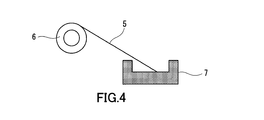
- a heating method other than the electron beam For example, when manufacturing a capacitor electrode plate, an aluminum oxide thin film is formed on the substrate 21. As shown in FIG. 4, aluminum can be dissolved and evaporated by resistance heating while supplying aluminum (aluminum wire 5) as a thin film constituent material from the raw material supplier 6 to the boat 7. When oxygen gas is supplied from the source gas introduction pipe 30 toward the film formation region 31, aluminum oxide is deposited on the substrate 21. A plurality of boats 7 may be arranged in the width direction of the substrate 21. The same applies to the evaporation source 9.
- the substrate 21 is transferred from the unwinding roller 23 to the take-up roller 26 along the transfer path (transfer process).
- a thin film is formed on the first main surface of the substrate 21 in the film forming region 31 set on the transport path (thin film forming step).
- an operation for supplying the substrate 21 from the unwinding roller 23 to the film forming region 31 and an operation for collecting the substrate 21 from the film forming region 31 to the take-up roller 26 are performed in synchronization. That is, the thin film manufacturing apparatus 100 ⁇ / b> A is a so-called winding type thin film manufacturing apparatus that forms a thin film on the substrate 21 being conveyed from the unwinding roller 23 to the winding roller 26. According to the roll-up type thin film manufacturing apparatus, high productivity can be achieved because continuous film formation for a long time is possible.
- the substrate 21 may be a discrete substrate.
- a large number of stacked substrates are sequentially sent from a delivery stocker to a film formation region. After film formation, the substrates are sequentially stored in a collection stocker.
- the substrate cooling material 10 can be applied to the discrete substrate on the transport path from the delivery stocker (delivery position) to the film formation region.
- the conveyance speed of the substrate 21 varies depending on the type of thin film and film forming conditions, and is, for example, 0.1 to 500 m / min.
- the average film formation rate is not particularly limited, and is, for example, 20 to 800 nm / second.
- a tension having an appropriate strength is applied to the substrate 21 being transported in the longitudinal direction of the substrate 21. The strength of the tension is appropriately adjusted depending on conditions such as the material of the substrate 21, the thickness of the substrate 21, and the film forming speed.
- a metal mask having an opening length of 50 to 400 mm in the width direction of the substrate 21 is disposed in the film formation region 31 so that a thin film having a certain width (for example, 100 to 600 mm) is formed on the substrate 21. (Not shown).
- the distance from the substrate 21 to the metal mask is, for example, 1 to 8 mm.
- the coater 11 Prior to the thin film forming process, the coater 11 is used to apply the substrate cooling material 19 to the second main surface of the substrate 21 on the transport path between the unwinding roller 23 and the film forming region 31 (applying process). .
- the substrate cooling material 10 is discharged from the discharge port 37 of the coater 11 in the form of vapor, reaches the second main surface of the substrate 21, and is liquefied or solidified into a thin film on the second main surface.
- the substrate cooling material 10 maintains a liquid phase or a solid phase state on the second main surface before the thin film forming step. Therefore, the substrate 21 can be cooled by the heat of vaporization (latent heat) of the substrate cooling material 10. This point is greatly different from conventional gas cooling.
- a material containing at least one selected from the group consisting of hydrocarbons, oils and higher alcohols can be used. These materials are suitable because they hardly remain as residues on the substrate 21.
- the hydrocarbon include alkanes such as decane, undecane, dodecane, and tridecane.
- the oil include fluorine oils such as Fomblin (registered trademark of Solvay Solexis) Y03, Fomblin Y06, and the like.
- the higher alcohol include those having 8 to 12 carbon atoms, such as octanol.
- a polymer material having a relatively low melting point such as low-density polyethylene can be used.
- a liquid or solid material can be used for the substrate cooling material 10 in a vacuum environment when forming a thin film.
- the composition of the substrate cooling material 10 includes the material of the substrate 21, the thickness of the substrate 21, the temperature reached by the substrate 21, the constituent material of the thin film, the deposition rate, the intensity of radiant heat, the required degree of cooling, the degree of vacuum, etc. Appropriately determined in consideration of various conditions.
- octanol can be used as the substrate cooling material 10.
- a discharge port 37 provided with a porous metal sintered body can be used.
- fluorine oil can be used as the substrate cooling material 10.
- one having a plurality of discharge ports 37 can be used.
- the thickness of the substrate cooling material 10 on the second main surface of the substrate 21 is not particularly limited.
- the substrate cooling material 10 has a thickness of 5 to 100 nm.
- the substrate cooling material 10 applied to the substrate 21 is transported together with the substrate 21 and reaches the film formation region 31.
- a thin film is formed on the first main surface of the substrate 21 while receiving heat from the raw material particles flying from the evaporation source 9 and radiation heat from the evaporation source 9.
- the substrate cooling material 10 takes heat from the substrate 21 and evaporates.
- the substrate 21 is heated by the formation of a thin film while being cooled by evaporation of the substrate cooling material 10. Therefore, the temperature rise of the substrate 21 can be suppressed.
- the entire amount of the substrate cooling material 10 may evaporate in the film formation region 31 or may remain slightly on the substrate 21. Even if a small amount of the substrate cooling material 10 remains on the substrate 21, the possibility of adversely affecting the quality of the thin film is low.
- a step of removing the substrate cooling material 10 from the substrate 21 may be performed as necessary.
- the substrate cooling material 10 can be removed from the substrate 21 by a method such as wiping, heating, and plasma irradiation described later.
- the substrate cooling material 10 remaining on the substrate 21 and the substrate cooling material 10 adhering to the members inside the vacuum chamber 22 can be detected by an evolved gas analysis (EGA) or other microchemical analysis.
- ESA evolved gas analysis
- the substrate 21 after film formation is analyzed by the generated gas analysis method, it can be checked whether the substrate cooling material 10 remains on the substrate 21.
- the substrate 21 is unwound from the unwinding roller 23 and then reaches the film formation region 31 via the transport roller 24.
- a thin film is formed on the first main surface of the substrate 21.
- the source gas may be supplied from the source gas introduction pipe 30 toward the film formation region 31.
- a thin film made of a compound of the raw material held in the evaporation source 9 and the raw material supplied from the raw material gas introduction pipe 30 can be formed.
- the substrate 21 is taken up by the take-up roller 26 via another transport roller 24.
- the step of applying the substrate cooling material 10 to the second main surface of the substrate 21 and the step of forming a thin film are performed on the moving substrate 21. That is, each process is performed while moving the substrate 21 slowly. Therefore, a thin film can be formed with high productivity.
- the substrate 21 can be moved intermittently little by little. That is, the substrate cooling material 10 may be applied on the substrate 21 that is temporarily stopped, or a thin film may be formed.
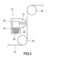
- FIG. 5 is a schematic view of a thin film manufacturing apparatus 100B provided with a sputtering source 8 as a film forming source.
- the sputter source 8 is disposed below the film formation region 31.
- the sputter source 8 can be used for manufacturing a transparent electrode, for example.
- a resin film such as a polyethylene terephthalate film can be used.
- an inert gas such as argon gas is introduced into the vacuum chamber 22, and the first target of the substrate 21 is formed by high-frequency sputtering using an ITO target that is a constituent material of the sputtering source 8.
- An ITO thin film is formed on the main surface.
- an ITO thin film having a thickness of 0.3 to 10 ⁇ m can be formed on a substrate 21 having a thickness of 10 to 150 ⁇ m.
- the average film formation rate by the sputtering method is generally slower than the average film formation rate by the vapor deposition method, for example, 0.5 to 5 nm / second.
- the conveyance speed of the substrate 21 is, for example, 0.05 to 1 m / min.
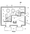
- FIG. 6 is a schematic diagram of a thin film manufacturing apparatus 100 ⁇ / b> C further including a plasma generator 14 and a heat receiving body 16 in addition to the configuration described with reference to FIG. 1. Only one of the plasma generator 14 and the heat receiving body 16 may be provided.
- the heat receiving body 16 faces the second main surface of the substrate 21 in the film formation region 31 and can receive heat from the substrate cooling material 10 evaporated from the second main surface of the substrate 21.
- the conveyance path is designed so that the substrate 21 travels linearly in the film formation region 31. Therefore, a member having a flat surface facing the substrate 21 can be suitably used as the heat receiving body 16. In this case, the distance between the heat receiving body 16 and the substrate 21 can be kept constant.
- the substrate cooling material 10 evaporates by heat applied to the substrate 21 in the film formation region 31 and takes heat of vaporization from the substrate 21.
- the evaporated substrate cooling material 10 stays for a while in the form of gas molecules between the substrate 21 and the heat receiving body 16.
- the gas molecules of the substrate cooling material 10 promote heat conduction between the substrate 21 and the heat receiving body 16. That is, the evaporated substrate cooling material 10 becomes a medium, and a high cooling effect can be obtained.
- One method for cooling the substrate in vacuum is to introduce a gas between the substrate and the support. According to this method, heat conduction between the substrate and the support is promoted by the gas.
- this modification both the effect of cooling the substrate 21 by the heat of vaporization of the substrate cooling material 10 and the effect of promoting the heat conduction between the substrate 21 and the heat receiving body 16 by the substrate cooling material 10 are obtained. It is done. Therefore, even if the load applied to the vacuum pump by gas cooling is approximately the same as the load applied to the vacuum pump 32 in this modification, this modification can exhibit a higher cooling effect than mere gas cooling.
- the heat receiving body 16 is preferably disposed near the substrate 21.
- the distance between the substrate 21 and the heat receiving body 16 is set to 0.1 to 3 mm, for example. When this interval is appropriately adjusted, the effect of promoting the heat conduction between the substrate 21 and the heat receiving body 16 by the evaporated substrate cooling material 10 is sufficiently prevented while preventing the heat receiving body 16 and the substrate 21 from contacting each other. Obtainable.
- the heat receiving body 16 also exhibits an effect of preventing the evaporated substrate cooling material 10 from being scattered inside the vacuum chamber 22. Therefore, the heat receiving body 16 preferably has a width wider than that of the substrate 21 in the width direction of the substrate 21.
- the heat receiving body 16 may be cooled by the cooler 39.
- the structure of the cooler 39 is not particularly limited. Examples of the cooler 39 include those using refrigerants such as water, antifreeze, and oil.
- the cooler 39 may be built in the heat receiving body 16 or may be only in contact with the heat receiving body 16.
- the heat receiving body 16 can be cooled by circulating the refrigerant cooled outside the vacuum chamber 22 to the cooler 39 using a refrigerator or the like.
- the material of the heat receiving body 16 is not particularly limited. A material such as metal, ceramic, or glass can be used as the material of the heat receiving body 16. When the heat receiving body 16 is made of a material that can easily maintain a low temperature and has a high emissivity, the effect of radiation cooling increases.
- the heat receiving body 16 may have a function of collecting the substrate cooling material 10.
- the lower part of the heat receiving body 16 faces the substrate 21, the lower part of the heat receiving body 16 may have an adsorption function.
- the heat receiving body 16 is composed of a simple metal block, the substrate cooling material 10 may adhere to the heat receiving body 16 without being exhausted and may eventually fall onto the substrate 21. In order to prevent this phenomenon, it is effective to provide holes and / or protrusions on the surface of the heat receiving body 16 or to provide a porous structure on the surface of the heat receiving body 16.
- part or all of the heat receiving body 16 may be made of an adsorbent that captures the substrate cooling material 10, typically a porous material. It is preferable that such an adsorbent is disposed in the film formation region 31 at a position facing the second main surface of the substrate 21 because the substrate cooling material 10 is unlikely to scatter in the vacuum chamber 22.
- the plasma generator 14 is provided on a conveyance path between the film formation region 31 and the take-up roller 26 (collection position). After film formation, the plasma generator 14 is used to decompose the substrate cooling material 10 remaining on the second main surface of the substrate 21.
- the plasma generator 14 includes a gas introduction tube 15, a discharge electrode 17, and a housing 20.
- the semi-sealed housing 20 is provided with two slits as entrances for the substrate 21.
- a conveyance path is set so that the substrate 21 passes through the inside of the housing 20.
- the gas introduction pipe 15 has one end connected to the housing 20 and the other end extending to the outside of the vacuum chamber 22.
- the other end of the gas introduction pipe 15 is connected to a gas supply source such as a gas cylinder or a gas generator outside the vacuum chamber 22.
- the discharge electrode 17 is provided inside the housing 20.
- the gas supplied to the housing 20 through the gas introduction tube 15 is excited by the discharge electrode 17, and plasma is generated inside the housing 20.
- the substrate cooling material 10 remaining on the substrate 21 is decomposed by the plasma generated around the substrate 21.
- the decomposition product of the substrate cooling material 10 is relatively easily separated from the substrate 21 and exhausted. Since the decomposition product has a smaller molecular weight than the substrate cooling material 10, it is exhausted as a gas with a high probability without adhering to the members inside the vacuum chamber 22.
- the composition of the process gas for generating plasma is not particularly limited.
- oxygen gas is used as a process gas for ashing organic substances.
- Oxygen gas is easy to handle.
- Oxygen plasma has a high ability to decompose organic substances, and can quickly decompose the substrate cooling material 10 into low molecular weight hydrocarbons, CO x , H 2 O, and the like.
- ozone gas, rare gas, nitrogen gas, halogen gas, hydrogen gas, chlorofluorocarbon gas and the like can be used. It is also possible to use a mixture of two or more gases, for example, a mixed gas of oxygen gas as a main component and a small amount of halogen gas.
- the “main component” means a component that is contained most in volume ratio.
- the flow rate of the process gas to be introduced into the housing 20 is not particularly limited, and is determined in consideration of the state of plasma discharge, the required degree of vacuum, and the like.
- the state of the plasma discharge also depends on the conductance of the housing 20 and the capacity of the exhaust pump 32. It should be noted that a sufficient degree of vacuum is required for the evaporation source 9 and the film formation region 31 in order to form a high-quality thin film.
- the flow rate of the process gas is controlled by a mass flow controller, and is, for example, 10 to 500 sccm (Standard Cubic Centimeter per Minute).
- the voltage to be applied to the discharge electrode 17 may be either direct current or alternating current.
- a high frequency voltage may be applied to the discharge electrode 17.
- the applied voltage is 500 to 1500 V, for example, although it depends on the pressure inside the casing 20 and the type of process gas.
- the supply power in the case of high frequency is, for example, 50 to 500 W (or 50 to 300 W).
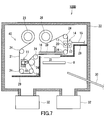
- FIG. 7 shows a combination of the first modification described with reference to FIG. 3 and the second modification described with reference to FIG. That is, the thin film manufacturing apparatus 100 ⁇ / b> D includes a sputtering source 8, a heat receiving body 16, and a plasma generator 14. As described above, the configurations described in the present specification can be appropriately combined as long as the cooling effect of the substrate 21 by the substrate cooling material 10 is obtained.
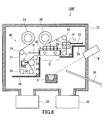
- FIG. 8 is a schematic diagram of a thin film manufacturing apparatus 100E further including a plasma generator 14 and a recovery mechanism 42 in addition to the configuration described with reference to FIG.
- the recovery mechanism 42 is provided at a position facing the second main surface of the substrate 21 staying in the film formation region 31. If the recovery mechanism 42 is used, the substrate cooling material 10 evaporated in the film formation region 31 can be efficiently recovered in the film formation region 31. Therefore, it is possible to prevent the substrate cooling material 10 from adversely affecting the quality of the thin film or scattering inside the vacuum chamber 22.
- the recovery mechanism 42 includes a gas introduction tube 15, a discharge electrode 17, an exhaust port 18, and a housing 43.
- the housing 43 opens toward the second main surface of the substrate 21, and prevents the substrate cooling material 10 evaporated from the second main surface of the substrate 21 from being scattered inside the vacuum chamber 22.
- the second main surface of the substrate 21 is covered with a housing 43.
- the exhaust port 18 is provided at a position facing the second main surface of the substrate 21 staying in the film formation region 31.
- a plurality of exhaust ports 18 are provided in a portion corresponding to the ceiling of the housing 43. The substrate cooling material 10 evaporated in the film forming region 31 is exhausted to the outside of the vacuum chamber 22 through the exhaust port 18.
- the position of the exhaust port 18 in the housing 43 is not particularly limited.
- the exhaust port 18 may not face the second main surface of the substrate 21.
- the substrate cooling material 10 is cooled through the exhaust port 18 before the substrate cooling material 10 leaks outside the housing 43 and diffuses into the vacuum chamber 22. The probability that the material 10 can be quickly exhausted to the outside of the vacuum chamber 22 is increased.
- an exhaust pipe 45 is connected to each exhaust port 18.
- the exhaust pipe 45 is connected to a vacuum pump 46 provided outside the vacuum chamber 22. That is, in addition to the vacuum pump 32 for exhausting the inside of the vacuum chamber 22, a vacuum pump 46 for exhausting the interior of the housing 43 through the exhaust port 18 and the exhaust pipe 45 is provided. According to such a structure, the substrate cooling material 10 can be recovered more efficiently.
- the dimension (inner diameter) of the exhaust port 18 is not particularly limited, and is, for example, 5 to 50 mm.
- the recovery mechanism 42 further includes a plasma generator 47.
- the plasma generator 47 includes the gas introduction tube 15 and the discharge electrode 17.
- the gas introduction pipe 15 has one end connected to the housing 43 and the other end extending to the outside of the vacuum chamber 22.
- the other end of the gas introduction pipe 15 is connected to a gas supply source such as a gas cylinder or a gas generator outside the vacuum chamber 22.
- the discharge electrode 17 is provided inside the housing 43. Specifically, the discharge electrode 17 is provided between the substrate 21 and the exhaust port 18.
- one end of the gas introduction pipe 15 opens toward the space between the substrate 21 and the exhaust port 18. According to such a positional relationship, plasma is generated in the space between the substrate 21 and the exhaust port 18.
- the substrate cooling material 10 evaporates in the film formation region 31 and is decomposed by plasma on the path from the substrate 21 to the exhaust port 18.
- the decomposition product of the substrate cooling material 10 is exhausted relatively easily.
- the housing 43 may have a wall portion in the width direction of the substrate 21.
- gas leakage can be reduced.
- FIG. 10 is a schematic view of a thin film manufacturing apparatus 100F further including a first plasma generator 14, a second plasma generator 54, and a cylindrical can 25 in addition to the configuration described with reference to FIG.
- the plasma generators 14 and 54 may be omitted.
- the thin film manufacturing apparatus 100F includes a transport system 50 having a cylindrical can 25 (can roller).
- the cylindrical can 25 is a roller-like member that can rotate at the same speed as the conveyance speed of the substrate 21, and is disposed in the film formation region 31. Specifically, a part of the outer peripheral surface of the cylindrical can 25 faces the film formation region 31. A part of the conveyance path by the conveyance system 50 is formed by a cylindrical can 25.
- a thin film is formed on the first main surface of the substrate 21.
- the cylindrical can 25 is often used when a thin film is formed on a long and strip-shaped substrate 21.
- the cylindrical can 25 has not only a role of forming a conveyance path, but also a role of a heat receiving body that receives heat from the substrate 21.
- the substrate cooling material 10 is not applied to the second main surface of the substrate 21.
- the heat of the substrate 21 moves to the cylindrical can 25 based on the direct contact between the substrate 21 and the cylindrical can 25.
- the substrate 21 is made of a metal foil, a region where the distance between the substrate 21 and the cylindrical can 25 exceeds 1 ⁇ m is likely to occur. Unless the substrate 21 and the cylindrical can 25 have extremely high dimensional accuracy, sufficient heat conduction cannot be expected.
- the substrate cooling material 10 evaporates by taking heat from the substrate 21 in the film formation region 31. Since the substrate 21 is supported by the cylindrical can 25, the gas molecules of the substrate cooling material 10 stay in a narrow space between the substrate 21 and the cylindrical can 25, and between the substrate 21 and the cylindrical can 25. Encourage heat conduction. That is, the evaporated substrate cooling material 10 becomes a medium, and a high cooling effect can be obtained. Similar to the second modification, both the effect of cooling the substrate 21 by the heat of vaporization of the substrate cooling material 10 and the effect of promoting the heat conduction between the substrate 21 and the cylindrical can 25 by the substrate cooling material 10 can be obtained. . In particular, in this modification, since the substrate 21 is supported by the cylindrical can 25, the substrate cooling material 10 can be easily confined in a narrow space between the substrate 21 and the cylindrical can 25. Therefore, the effect of promoting heat conduction can be obtained more sufficiently.
- the cylindrical can 25 may be cooled by a cooler.
- a cooler what was demonstrated in the modification 2 can be used, for example.
- the cylindrical can 25 preferably has a large heat capacity, and can be made of a metal material such as stainless steel, for example.
- the thin film manufacturing apparatus 100F also includes two plasma generators 14 and 54. Details of the first plasma generator 14 are as described in the second modification.
- the second plasma generator 54 plays a role of decomposing the substrate cooling material 10 attached to the outer peripheral surface of the cylindrical can 25. Thereby, it is possible to prevent the substrate cooling material 10 from accumulating in the cylindrical can 25.
- the second plasma generator 54 is provided near the cylindrical can 25 on the side opposite to the side facing the film formation region 31.
- the second plasma generator 54 includes the gas introduction tube 15, the discharge electrode 17, and the housing 55. Details of the gas introduction tube 15 and the discharge electrode 17 are as described in the second modification.
- the housing 55 opens toward the outer peripheral surface of the cylindrical can 25. As shown in FIG. 10, the casing 55 may have an opening that is curved along the outer peripheral surface of the cylindrical can 25 in order to enhance the confinement effect of the plasma generating gas.
- plasma low discharge plasma
- the outer peripheral surface of the cylindrical can 25 is exposed to the plasma. As a result, the substrate cooling material 10 adhering to the outer peripheral surface of the cylindrical can 25 is decomposed.
- the substrate 21 can be efficiently cooled while suppressing the deterioration of the degree of vacuum. Accordingly, it is possible to avoid an increase in the size of equipment such as a vacuum pump, and to achieve a high deposition rate at a low cost. Since the substrate 21 can be sufficiently cooled, the substrate 21 is not easily damaged by heat even if high-speed film formation is performed.
- the present invention can be applied to various uses that are required to form a thin film stably at high speed.
- the present invention can be suitably employed in the production of transparent electrodes, battery electrodes, and capacitor electrodes.
- the scope of application of the present invention is not limited to these.
- the present invention can be applied to the production of various films such as electrode plates for electrochemical capacitors, decorative films, solar cells, magnetic tapes, gas barrier films, sensors, optical films, and hard protective films.
- the present invention can be applied to an apparatus for manufacturing a device including a thin film.
Landscapes
- Chemical & Material Sciences (AREA)
- Engineering & Computer Science (AREA)
- Chemical Kinetics & Catalysis (AREA)
- Materials Engineering (AREA)
- Mechanical Engineering (AREA)
- Metallurgy (AREA)
- Organic Chemistry (AREA)
- Electrochemistry (AREA)
- General Chemical & Material Sciences (AREA)
- Manufacturing & Machinery (AREA)
- Physical Vapour Deposition (AREA)
- Cell Electrode Carriers And Collectors (AREA)
- Battery Electrode And Active Subsutance (AREA)
Abstract
L'invention porte sur un dispositif de production de couche mince (100A) doté d'une cuve à vide (22), d'une source de dépôt (9) (source d'évaporation), d'un système de transport (40) et d'un dispositif d'enduction (11). La source de dépôt (9) est utilisée pour former une couche mince sur une première surface principale d'un substrat (21) dans une zone de dépôt (31) dans la cuve à vide (22). Le système de transport (40) est responsable du transport du substrat (21) d'un rouleau de déroulage (23) (position initiale) vers un rouleau d'enroulage (26) (position de récupération) le long d'un trajet de transport conçu de façon à ce que le substrat (21) passe dans la région de dépôt (31). Lors de la formation de la couche mince, le dispositif d'enduction (11) applique sur une seconde surface principale du substrat (21) une matière de refroidissement de substrat (10) qui peut être amenée à s'évaporer par l'application de chaleur au substrat (21).
Priority Applications (2)
| Application Number | Priority Date | Filing Date | Title |
|---|---|---|---|
| JP2012523161A JP5058396B1 (ja) | 2011-03-11 | 2012-01-23 | 薄膜の製造方法及び製造装置 |
| CN2012800091601A CN103392025A (zh) | 2011-03-11 | 2012-01-23 | 薄膜的制造方法和制造装置 |
Applications Claiming Priority (2)
| Application Number | Priority Date | Filing Date | Title |
|---|---|---|---|
| JP2011-054719 | 2011-03-11 | ||
| JP2011054719 | 2011-03-11 |
Publications (1)
| Publication Number | Publication Date |
|---|---|
| WO2012124246A1 true WO2012124246A1 (fr) | 2012-09-20 |
Family
ID=46830343
Family Applications (1)
| Application Number | Title | Priority Date | Filing Date |
|---|---|---|---|
| PCT/JP2012/000400 Ceased WO2012124246A1 (fr) | 2011-03-11 | 2012-01-23 | Procédé de production de couche mince et dispositif de production de couche mince |
Country Status (3)
| Country | Link |
|---|---|
| JP (1) | JP5058396B1 (fr) |
| CN (1) | CN103392025A (fr) |
| WO (1) | WO2012124246A1 (fr) |
Cited By (5)
| Publication number | Priority date | Publication date | Assignee | Title |
|---|---|---|---|---|
| JP2016219186A (ja) * | 2015-05-18 | 2016-12-22 | 株式会社アルバック | 正極活物質膜、および、成膜方法 |
| WO2019024326A1 (fr) * | 2017-07-31 | 2019-02-07 | 武汉华星光电半导体显示技术有限公司 | Appareil d'évaporation |
| JP2020158867A (ja) * | 2019-03-28 | 2020-10-01 | 芝浦メカトロニクス株式会社 | 成膜装置 |
| CN114231909A (zh) * | 2016-04-28 | 2022-03-25 | 佳能特机株式会社 | 真空蒸镀装置以及蒸发源的冷却方法 |
| WO2024233691A1 (fr) * | 2023-05-11 | 2024-11-14 | Applied Materials, Inc. | Revêtement de lithium par l'intermédiaire de rouleaux à effleurement |
Families Citing this family (3)
| Publication number | Priority date | Publication date | Assignee | Title |
|---|---|---|---|---|
| CN108220890B (zh) * | 2016-12-15 | 2020-02-14 | 中国航空工业集团公司济南特种结构研究所 | 一种复材表面电弧离子镀膜方法 |
| CN112606372A (zh) * | 2020-12-15 | 2021-04-06 | 广东正一包装股份有限公司 | 一种高阻隔镀铝聚乙烯薄膜的制备方法 |
| CN113684464B (zh) * | 2021-08-27 | 2023-06-02 | 辽宁分子流科技有限公司 | 一种用于石墨烯复合薄膜制备的卷绕式设备 |
Citations (5)
| Publication number | Priority date | Publication date | Assignee | Title |
|---|---|---|---|---|
| JPH0348853U (fr) * | 1989-09-20 | 1991-05-10 | ||
| JP2006250909A (ja) * | 2005-03-14 | 2006-09-21 | Fuji Photo Film Co Ltd | 放射線像変換パネル |
| JP2009149963A (ja) * | 2007-12-22 | 2009-07-09 | Sumitomo Metal Mining Co Ltd | 真空成膜方法及び真空成膜装置 |
| WO2009104382A1 (fr) * | 2008-02-20 | 2009-08-27 | パナソニック株式会社 | Appareil de formation de film mince et procédé de formation de film mince |
| JP2010080855A (ja) * | 2008-09-29 | 2010-04-08 | Nikon Corp | 露光装置、露光方法及びデバイスの製造方法 |
Family Cites Families (1)
| Publication number | Priority date | Publication date | Assignee | Title |
|---|---|---|---|---|
| WO2007114314A1 (fr) * | 2006-03-30 | 2007-10-11 | Kabushiki Kaisha Mikuni Kogyo | Procede pour la formation d'une minuscule bosse metallique |
-
2012
- 2012-01-23 CN CN2012800091601A patent/CN103392025A/zh active Pending
- 2012-01-23 JP JP2012523161A patent/JP5058396B1/ja not_active Expired - Fee Related
- 2012-01-23 WO PCT/JP2012/000400 patent/WO2012124246A1/fr not_active Ceased
Patent Citations (5)
| Publication number | Priority date | Publication date | Assignee | Title |
|---|---|---|---|---|
| JPH0348853U (fr) * | 1989-09-20 | 1991-05-10 | ||
| JP2006250909A (ja) * | 2005-03-14 | 2006-09-21 | Fuji Photo Film Co Ltd | 放射線像変換パネル |
| JP2009149963A (ja) * | 2007-12-22 | 2009-07-09 | Sumitomo Metal Mining Co Ltd | 真空成膜方法及び真空成膜装置 |
| WO2009104382A1 (fr) * | 2008-02-20 | 2009-08-27 | パナソニック株式会社 | Appareil de formation de film mince et procédé de formation de film mince |
| JP2010080855A (ja) * | 2008-09-29 | 2010-04-08 | Nikon Corp | 露光装置、露光方法及びデバイスの製造方法 |
Cited By (9)
| Publication number | Priority date | Publication date | Assignee | Title |
|---|---|---|---|---|
| JP2016219186A (ja) * | 2015-05-18 | 2016-12-22 | 株式会社アルバック | 正極活物質膜、および、成膜方法 |
| CN114231909A (zh) * | 2016-04-28 | 2022-03-25 | 佳能特机株式会社 | 真空蒸镀装置以及蒸发源的冷却方法 |
| CN114231909B (zh) * | 2016-04-28 | 2023-12-01 | 佳能特机株式会社 | 真空蒸镀装置以及蒸发源的冷却方法 |
| WO2019024326A1 (fr) * | 2017-07-31 | 2019-02-07 | 武汉华星光电半导体显示技术有限公司 | Appareil d'évaporation |
| JP2020158867A (ja) * | 2019-03-28 | 2020-10-01 | 芝浦メカトロニクス株式会社 | 成膜装置 |
| JP7319799B2 (ja) | 2019-03-28 | 2023-08-02 | 芝浦メカトロニクス株式会社 | 成膜装置 |
| JP2023133417A (ja) * | 2019-03-28 | 2023-09-22 | 芝浦メカトロニクス株式会社 | 成膜装置 |
| JP7664974B2 (ja) | 2019-03-28 | 2025-04-18 | 芝浦メカトロニクス株式会社 | 成膜装置 |
| WO2024233691A1 (fr) * | 2023-05-11 | 2024-11-14 | Applied Materials, Inc. | Revêtement de lithium par l'intermédiaire de rouleaux à effleurement |
Also Published As
| Publication number | Publication date |
|---|---|
| CN103392025A (zh) | 2013-11-13 |
| JPWO2012124246A1 (ja) | 2014-07-17 |
| JP5058396B1 (ja) | 2012-10-24 |
Similar Documents
| Publication | Publication Date | Title |
|---|---|---|
| JP5058396B1 (ja) | 薄膜の製造方法及び製造装置 | |
| JP6724967B2 (ja) | プラズマを使った前処理装置を有した蒸着装置 | |
| CN102245800B (zh) | 薄膜的形成方法 | |
| CN101889103B (zh) | 薄膜形成装置和薄膜形成方法 | |
| US8877291B2 (en) | Method of manufacturing thin film which suppresses unnecessary scattering and deposition of a source material | |
| US8697582B2 (en) | Substrate conveying roller, thin film manufacturing device, and thin film manufacturing method | |
| JP5807216B2 (ja) | 薄膜の製造方法 | |
| TW201502307A (zh) | 成膜裝置及成膜方法 | |
| US20180298483A1 (en) | Method and coating arrangement | |
| JP2023502640A (ja) | スパッタ堆積 | |
| JPWO2018193993A1 (ja) | 成膜装置及び成膜方法 | |
| JP2012197477A (ja) | 薄膜製造方法および装置 | |
| JP2013008602A (ja) | リチウム二次電池用負極の製造装置および製造方法 | |
| TW200304498A (en) | Method and apparatus for manufacturing thin film | |
| JP5050650B2 (ja) | 真空成膜方法 | |
| JP2012144783A (ja) | 薄膜製造装置及び薄膜製造方法 | |
| US20250236946A1 (en) | Vacuum treatment apparatus and vacuum treatment method | |
| US20260043128A1 (en) | Processing apparatus for processing a flexible substrate and methods therefor | |
| JP2012172261A (ja) | 成膜装置 | |
| WO1987005637A1 (fr) | Dispositif de plaquage ionique continu pour un film a defilement rapide | |
| JP2015209577A (ja) | 成膜装置および成膜方法 | |
| JP2012172260A (ja) | 成膜装置 | |
| JP2004018895A (ja) | 薄膜製造装置、薄膜の製造方法および薄膜蒸着シートの製造方法 |
Legal Events
| Date | Code | Title | Description |
|---|---|---|---|
| ENP | Entry into the national phase |
Ref document number: 2012523161 Country of ref document: JP Kind code of ref document: A |
|
| 121 | Ep: the epo has been informed by wipo that ep was designated in this application |
Ref document number: 12757495 Country of ref document: EP Kind code of ref document: A1 |
|
| NENP | Non-entry into the national phase |
Ref country code: DE |
|
| 122 | Ep: pct application non-entry in european phase |
Ref document number: 12757495 Country of ref document: EP Kind code of ref document: A1 |