WO2012124254A1 - Bloc de récif pour poissons et d'absorption des vagues - Google Patents
Bloc de récif pour poissons et d'absorption des vagues Download PDFInfo
- Publication number
- WO2012124254A1 WO2012124254A1 PCT/JP2012/000957 JP2012000957W WO2012124254A1 WO 2012124254 A1 WO2012124254 A1 WO 2012124254A1 JP 2012000957 W JP2012000957 W JP 2012000957W WO 2012124254 A1 WO2012124254 A1 WO 2012124254A1
- Authority
- WO
- WIPO (PCT)
- Prior art keywords
- wave
- dissipating
- frame body
- fish reef
- projecting
- Prior art date
- Legal status (The legal status is an assumption and is not a legal conclusion. Google has not performed a legal analysis and makes no representation as to the accuracy of the status listed.)
- Ceased
Links
Images











Classifications
-
- E—FIXED CONSTRUCTIONS
- E02—HYDRAULIC ENGINEERING; FOUNDATIONS; SOIL SHIFTING
- E02B—HYDRAULIC ENGINEERING
- E02B3/00—Engineering works in connection with control or use of streams, rivers, coasts, or other marine sites; Sealings or joints for engineering works in general
- E02B3/04—Structures or apparatus for, or methods of, protecting banks, coasts, or harbours
- E02B3/06—Moles; Piers; Quays; Quay walls; Groynes; Breakwaters ; Wave dissipating walls; Quay equipment
-
- A—HUMAN NECESSITIES
- A01—AGRICULTURE; FORESTRY; ANIMAL HUSBANDRY; HUNTING; TRAPPING; FISHING
- A01K—ANIMAL HUSBANDRY; AVICULTURE; APICULTURE; PISCICULTURE; FISHING; REARING OR BREEDING ANIMALS, NOT OTHERWISE PROVIDED FOR; NEW BREEDS OF ANIMALS
- A01K61/00—Culture of aquatic animals
- A01K61/70—Artificial fishing banks or reefs
-
- E—FIXED CONSTRUCTIONS
- E02—HYDRAULIC ENGINEERING; FOUNDATIONS; SOIL SHIFTING
- E02B—HYDRAULIC ENGINEERING
- E02B3/00—Engineering works in connection with control or use of streams, rivers, coasts, or other marine sites; Sealings or joints for engineering works in general
- E02B3/04—Structures or apparatus for, or methods of, protecting banks, coasts, or harbours
- E02B3/046—Artificial reefs
-
- Y—GENERAL TAGGING OF NEW TECHNOLOGICAL DEVELOPMENTS; GENERAL TAGGING OF CROSS-SECTIONAL TECHNOLOGIES SPANNING OVER SEVERAL SECTIONS OF THE IPC; TECHNICAL SUBJECTS COVERED BY FORMER USPC CROSS-REFERENCE ART COLLECTIONS [XRACs] AND DIGESTS
- Y02—TECHNOLOGIES OR APPLICATIONS FOR MITIGATION OR ADAPTATION AGAINST CLIMATE CHANGE
- Y02A—TECHNOLOGIES FOR ADAPTATION TO CLIMATE CHANGE
- Y02A10/00—TECHNOLOGIES FOR ADAPTATION TO CLIMATE CHANGE at coastal zones; at river basins
- Y02A10/11—Hard structures, e.g. dams, dykes or breakwaters
-
- Y—GENERAL TAGGING OF NEW TECHNOLOGICAL DEVELOPMENTS; GENERAL TAGGING OF CROSS-SECTIONAL TECHNOLOGIES SPANNING OVER SEVERAL SECTIONS OF THE IPC; TECHNICAL SUBJECTS COVERED BY FORMER USPC CROSS-REFERENCE ART COLLECTIONS [XRACs] AND DIGESTS
- Y02—TECHNOLOGIES OR APPLICATIONS FOR MITIGATION OR ADAPTATION AGAINST CLIMATE CHANGE
- Y02A—TECHNOLOGIES FOR ADAPTATION TO CLIMATE CHANGE
- Y02A40/00—Adaptation technologies in agriculture, forestry, livestock or agroalimentary production
- Y02A40/80—Adaptation technologies in agriculture, forestry, livestock or agroalimentary production in fisheries management
- Y02A40/81—Aquaculture, e.g. of fish
Definitions
- the present invention relates to a wave-dissipating / fish-reef block that constitutes a wave-dissipating function and a reef function by being installed in water and connected to each other.
- Embankments breakwaters, breakwater piers, artificial reefs, lanterns, diversion banks, etc. may be installed.
- This fish reef block is a man-made fish reef by submerging a concrete block, etc., and algae, adhering organisms or feed organisms are propagated to provide fish feeding grounds, nursery grounds, egg laying grounds, and fish breeding and proliferation. It is. Under such circumstances, a concrete fish reef block is usually formed by placing concrete in a formwork.
- the conventional fish reef block is formed into a hollow three-dimensional shape in which a block body formed of concrete or iron is provided with a hole or the like to open each surface.
- a reef concrete block is formed by placing concrete on a manufacturing formwork and solidifying it to form a block body, then curing it for a predetermined period of time to solidify the concrete, and then removing the block body from the formwork. To do.
- the present invention has been devised in view of the above-described problems, and the object of the present invention is to provide an erasing function that has both a wave-dissipating function and a fish reef function, and can be stratified and stacked firmly.
- the purpose is to provide waves and reef blocks.
- the wave-dissipating and reef block according to the present invention is a wave-dissipating and reef block that forms a wave-dissipating and reef body by being fitted and connected to each other in water.
- An upper frame body and a lower frame body, each having a through hole formed substantially at the center, are integrated via a column body or a plate-like body, and a plurality of projecting bodies project from the corners of each frame body.
- the side surface of each frame body and the outer side surface of the projecting body are substantially vertical and substantially flat, and the other side surface of the projecting body is in contact with a through hole of the reef block and the other wave-dissipating body.
- the side surface of the through hole of the fish reef block has a taper with the same slope so as to be aligned with each other, and the inclination angle of the taper formed with the same slope with respect to the horizontal direction is 30 to 80 °.
- the body's through hole is the protruding body in several other wave-dissipating and reef blocks.
- the projecting body of each frame body can be inserted into the through hole in the other wave-dissipating / fish reef block through the taper. It is possible to insert it as possible.
- the assembling method of the wave-dissipation / fish reef body according to the present invention is a method of assembling the wave-dissipation / fish reef body by fitting and connecting the wave-dissipation / fish reef blocks together.
- the upper frame body and the lower frame body in which a recess is formed in the center are integrated via a column body or a plate-like body, and a plurality of projecting bodies project from the corners of each frame body, A taper with the same gradient is formed so that the inner side surface of the projecting body in contact with the through hole of the other wave-dissipating / fish reef block and the side surface of the through-hole of the other wave-dissipating / reef block are aligned with each other.
- a plurality of other wave-dissipating / fish reef blocks projecting bodies are respectively provided in the recesses of each frame.
- wave energy is converted into vortex by vortexing the wave in the hollow portion by the effect of the columnar body or plate-like body in the wave extinction / fish reef block.
- wave energy can be attenuated by stacking blocks with complex shapes and irregularities to form a complex and narrow underwater maze to disperse and attenuate the wave energy, or by vortexing the wave to generate wave energy.
- the method of the present invention is a method of converting wave energy into a vortex and attenuating it.
- it provides underwater caves and artificial reefs in shallow seas and lakes as fish reefs, and plays a role as a fish reef that grows algae and attached organisms to form fish spawning grounds, fry nurseries, and fish dwellings. Is possible.
- A is a cross-sectional view taken along the line AA in FIG. 2
- B is a cross-sectional view taken along the line BB in FIG.
- A is a cross-sectional view taken along the line AA in FIG. 2
- B is a cross-sectional view taken along the line BB in FIG.
- A is a cross-sectional view taken along the line AA in FIG. 2
- B is a cross-sectional view taken along the line BB in FIG.
- It is a perspective view of the wave-dissipating and reef block provided with the plate-shaped body. It is a side view of the wave-dissipation and fish reef block which provided the plate-shaped object.
- A is a CC cross-sectional view of FIG. 6, and B is a DD cross-sectional view of FIG.
- It is a perspective view of the modification of the wave-dissipation and fish reef block to which this invention is applied.
- It is a side view of the modification of the wave-dissipation and a fish reef block to which this invention is applied.
- It is a top view of the modification of the wave-dissipation and a fish reef block to which this invention is applied.
- A is a cross-sectional view taken along line EE in FIG. 10
- B is a cross-sectional view taken along line FF in FIG.
- FIG. 1 It is a figure which shows the detailed structure of the edge block used for the outermost part of the wave bottom and a reef block layer which piles up the outer edge wall of a wave bottom and a reef body perpendicularly
- a wave-dissipating / reef block that can be installed in the sea, a lake, or the like and has both a wave-dissipating function and a fish-reef function will be described in detail.
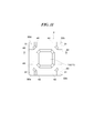
- FIG. 1 is a perspective view of a wave-absorbing / fish reef block 1 to which the present invention is applied
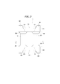
- FIG. 2 is a side view thereof
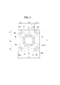
- FIG. 3 is a plan view thereof.
- This wave-dissipation / fish reef block 1 is a block that constitutes a wave-dissipation / fish reef body by being installed in water and connected to each other.
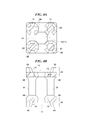
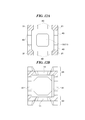
- 4A is a cross-sectional view taken along the line AA in FIG. 2
- FIG. 4B is a cross-sectional view taken along the line BB in FIG.
- This wave-dissipating / fish reef block 1 an upper frame body 21 in which a through hole 10 is formed at a substantially center and a lower frame body 22 in which a through hole 11 is formed in a substantially center are integrated via a column body 31. It becomes.
- a plurality of projecting bodies 32a to 32d project from the corner of the upper frame 21 upward, and a plurality of projecting bodies 33a to 33d project from the corner of the lower frame 22 downward.
- This wave-dissipating / fish reef block 1 is made of concrete and manufactured by integral molding.
- the upper frame body 21 and the lower frame body 22 are described as an example in which each of the upper frame body 21 and the lower frame body 22 is square in plan view.
- the present invention is not limited to this, but is rectangular, rhombus, trapezoid, parallelogram, regular A triangle, an isosceles triangle, a regular hexagon, a regular hexagon, and a hexagon with two opposite sides extended.
- the planar shapes of the upper frame body 21 and the lower frame body 22 are preferably square, rectangular or regular hexagonal.
- the planar shapes of the upper frame body 21 and the lower frame body 22 are configured so that the inner angles of the sides are 90 ° and 120 °, respectively.
- the corners constituting the upper frame body 21 (lower frame body 22) are collected at one point in the corners of the upper frame body 21 (lower frame body 22) adjacent to each other, the total of the inner angles is 360. It is only necessary to have a shape that forms an angle.
- the foundation surface for constructing the wave-dissipating / reef body should be smooth and level, the actual foundation surface may have some irregularities.
- the dimensions of the projecting bodies 32 and 33 are made slightly smaller than the dimensions of the through holes 10 and 11. Produce wave / fish reef block 1.
- the projecting bodies 33 in a plurality of other wave-dissipating / reef blocks 1 can be inserted into the through holes 10 respectively.
- the projecting bodies 32 in a plurality of other wave-dissipating / reef blocks 1 can be inserted into the through holes 11, respectively.
- the through holes 10 and 11 are in accordance with the size of the design dimension.
- the dimensions of the projecting body 33 inserted into the through hole 10 and the projecting body 32 inserted into the through hole 11 are as follows. It is necessary that the size be slightly smaller than the size of the through-hole holes 10 and 11.
- the through hole 10 may be configured with any diameter. However, as shown in FIG.
- the through-holes 10 and 11 are polygons obtained by extending two opposite symmetric sides at the same ratio in a square, rectangle, rhombus, trapezoid, parallelogram, regular triangle, isosceles triangle, regular hexagon, and regular polygon.
- a polygon including an octagon
- a polygon that is symmetrical with two sides facing each other, a circle, an ellipse, and a composite shape combining any two or more of the above shapes, or the above shape, It may be configured in any shape.
- the projecting bodies 33 and 32 need to be able to penetrate the through holes 10 and 11, and the through holes and the projecting bodies need to be aligned with each other.
- the shape of the through holes 10 and 11 is desirably provided with a haunch portion 14 at a corner portion in plan view in order to alleviate stress concentration.
- the stress concentration at the corners in the through holes 10 and 11 can be dispersed, and the occurrence of cracks from the corners can be prevented or reduced.
- the taper 15 may be formed in the side surface in the through-holes 10 and 11 and the side surface of the projecting bodies 32 and 33.
- the through hole 10 may be configured to have a tapered shape so that the diameter gradually decreases as it goes downward and the through hole 11 goes upward.
- the through holes 10 and 11 are not limited to the case where the bottom surface is configured as a through hole as described above, and the bottom surface may be configured as a non-penetrating recess.
- the projecting bodies 32 can be inserted into the through holes 11 in the other wave-dissipating / fish reef blocks 1 adjacent to the upper side together with the projecting bodies 32 of the other wave-dissipating / fish reef blocks 1 adjacent in the horizontal direction.
- the projecting body 33 can be inserted into the through holes 10 in the other wave-dissipating / fish reef blocks 1 adjacent to the lower side together with the projecting bodies 33 of the other wave-dissipating / fish reef blocks 1 adjacent in the horizontal direction.
- the projecting bodies 32 and 33 correspond to the size of the design dimension, but the dimensions of the projecting body 33 inserted into the through hole 10 and the projecting body 32 inserted into the through hole 11 are as follows. The dimensions need to be slightly smaller than the dimensions of the through holes 10 and 11.
- the projecting bodies 32 and 33 are polygons obtained by extending two opposite symmetric sides at the same ratio in a square, rectangle, rhombus, trapezoid, parallelogram, regular triangle, isosceles triangle, pentagon, regular hexagon, and regular polygon.
- the shape is a regular hexagon that is bisected by the symmetry axis, a partial hexagon (a trapezoid when the corner is bisected, and a pentagon that is a home base when the center is bisected), and a polygon that has two opposite sides symmetrical ( (Including octagons), partial polygons obtained by dividing a polygon with two opposite sides symmetrical by a symmetric axis, a circle, an ellipse, a semicircle / semi-elliptical shape obtained by dividing a circle / ellipse with a straight line, and such semicircles -It may be composed of a combination of a semi-elliptical shape and a rectangle, and a composite shape combining any two or more of the above-mentioned shapes, or any shape without being limited to the above-mentioned shapes. May be. However, it is necessary that the projecting bodies 33 and 32 can penetrate the through holes 10 and 11 and the through holes and the projecting bodies are
- the projecting bodies 32 and 33 may be chamfered at corners in plan view. Thereby, it is possible to reduce the chipping of the corners. Further, a taper 15 having a slightly smaller diameter than the taper of the through holes 10 and 11 described above may be formed on the side surfaces of the projecting bodies 32 and 33. Note that the inclination angle ⁇ shown in FIG. 4B with respect to the horizontal direction of the taper 15 is preferably 30 to 80 °.
- the protruding body 32 may be configured to have a tapered shape so that the diameter gradually decreases as the protruding body 32 moves upward and the protruding body 33 moves downward.
- the projecting bodies 32 and 33 may be configured in a truncated pyramid shape having a gradually reduced diameter at the tip, a truncated cone shape, an elliptical truncated cone shape, or a combination of these shapes.
- the column body 31 is provided to connect and integrate the upper frame body 21 and the lower frame body 22 in the wave-dissipating / fish reef block 1.
- the cross-sectional shape of the column 31 is a square, a rectangle, a rhombus, a trapezoid, a parallelogram, a regular triangle, an isosceles triangle, a pentagon, a regular hexagon, and a symmetric two sides that extend from each other at the same ratio.
- Polygon shape partial hexagon that bisects regular hexagon with symmetry axis, polygon that has two opposite sides symmetrical (including octagon), and part that divides polygon that has two opposite sides symmetrical with symmetry axis
- You may be comprised by the composite shape.
- the diameter of the column body 31 is determined according to the strength required in the actual use environment.
- the arrangement position of the column 31 in plan view is substantially the same as the protruding bodies 32 and 33 shown in FIG.
- a haunch 38 is provided at a connecting portion between the column body 31 and the upper frame body 21 and the lower frame body 22. That is, the haunch 38 is expanded in diameter from the column body 31 toward the upper frame body 21 and the lower frame body 22.
- the upper frame body 21 and the lower frame body 22 each provided with the through holes 10 and 11 and the projecting bodies 32 and 33 are integrally formed via the column body 31.
- the wave-dissipating / fish reef block 1 forms a wave-dissipating / fish reef body that is firmly connected in the vertical direction and the horizontal direction. By constructing such a tightly connected structure, this wave-dissipating / fish reef block 1 is installed underwater in a stratified stack, which transforms wave energy into vortices and attenuates it, and exerts its effect as a fish reef. is there.
- any one of the above-described upper frame body 21 and lower frame body 22, projecting bodies 32 and 33, and column body 31 is a detailed view of the convex portion and the corner portion of the concave portion, so that chamfering (not shown) is performed. It may be.
- the chamfering (not shown) is preferably about C30 to C50. By performing such chamfering, it is possible to prevent or reduce the occurrence of such corner cracks or cracks.
- the size of the wave-dissipating / fish reef block 1 is exemplified by a case where the block is composed of a substantially cubic block body having a length and width of about 3 m and projecting bodies 32 and 33 having a height of about 0.4 m. Of course, the size is not limited. Further, the wave-dissipating / fish reef block 1 is not limited to a cube, and may be a rectangular parallelepiped shape or a regular hexagonal shape in plan view.
- reinforcing bars may be arranged inside any one or all of the upper frame body 21, the lower frame body 22, the projecting bodies 32 and 33, and the column body 31.
- the reinforcing bars arranged inside this block This can be countered through.
- the concrete covering thickness with respect to the reinforcing bars is 8 cm or more for the auxiliary reinforcing bars and 10 cm or more for the main reinforcing bars.
- this wave-dissipation / fish reef block 1 is assumed to be installed in the sea, in order to prevent corrosion of the reinforcing bar due to seawater, etc., a material that is resistant to corrosion is selected as the material constituting the reinforcing bar. It is desirable to take anti-rust measures such as painting or plating.
- the wave-dissipation / fish reef block 1 to which the present invention is applied is not limited to the embodiment described above.
- a plate-like body provided with a horizontal hole may be provided instead of providing the column body 31 described above.
- FIG. 5 is a perspective view of the wave-absorbing / fish reef block 2 provided with such a plate-like body 40
- FIG. 6 is a side view thereof
- FIG. 7 is a plan view thereof
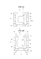
- 8A is a sectional view taken along the line CC in FIG. 6,
- FIG. 8B is a sectional view taken along the line DD in FIG.
- the same components / members as those of the wave-dissipation / fish reef block 1 described above are denoted by the same reference numerals, and the following description is omitted.
- the wave-dissipating / fish reef block 2 has a plate-like shape in which an upper frame body 21 having a through hole 10 formed at a substantially central portion and a lower frame body 22 having a through hole 11 formed at a substantially central portion provided with a horizontal hole 41. It is integrated through the body 40.
- a plurality of projecting bodies 32a to 32d project from the corner of the upper frame 21 upward, and a plurality of projecting bodies 33a to 33d project from the corner of the lower frame 22 downward. has been.
- the plate-like body 40 is provided over four surfaces so as to surround the inside of the block from the outside. Thereby, the plate-like body 40 is configured so that the inside is hollow. Since this plate-like body 40 is disposed so as to intersect with each other at the corners of the block and supports the upper frame body 21 and the lower frame body 22 as an alternative to the column body 31, its strength In some cases, it is required to increase the thickness. For example, in the case where it is provided in the middle between the upper frame body 21 and the lower frame body 22 in 3 m square, it is desirable that the thickness of the plate-shaped body 40 is 0.4 m or more. Note that reinforcing bars may also be arranged in the plate-like body 40. Incidentally, this plate-like body 40 may be integrally formed between the upper frame body 21 and the lower frame body 22, or a structure in which those separately produced are joined later. It is good.
- a haunch portion (not shown) may be provided at the inner corner 120 of the L-shaped plate.
- a haunch portion (not shown) may be provided at the joint portion 121 between the plate-like body 40 and the frame bodies 21 and 22.
- the lateral hole 41 is disposed so as to penetrate the substantially central portion of the plate-like body 40.
- the horizontal hole 41 may have any shape, but in the example of FIG. 5, it is formed of an octagon. As a result, it is possible to prevent or reduce stress concentration at the corners as compared to the case of a quadrangular shape.
- the diameter of the horizontal hole 41 is appropriately designed so as to satisfy the requirements of strength, wave-dissipating effect, and fish reef effect.
- FIGS. 9 to 12 show modifications of the wave-dissipating / fish reef block 2. From the viewpoint of further reinforcing the strength surface of the plate-like body 40 described above, a column body 31 is provided at the intersection of the plate-like body 40.
- FIG. 9 is a perspective view of a modified example of the wave-dissipating / fish reef block 2
- FIG. 10 is a side view thereof
- FIG. 11 is a plan view thereof.
- 12A is a cross-sectional view taken along the line EE in FIG. 10
- FIG. 12B is a cross-sectional view taken along the line FF in FIG.
- the same components and members as those in FIGS. 1 to 8 described above are denoted by the same reference numerals, and the following description is omitted.
- the upper frame body 21 and the lower frame body 22 can be mainly supported via the column body 31, so that the plate thickness of the plate-like body 40 can be reduced.
- this formwork has a basic configuration even if the shape and external dimensions of the wave-dissipating / fish reef blocks 1 and 2 are different. Is common.
- this basic configuration can be made into one unit configuration, and it becomes possible to make a mold frame by combining or continuous unit configurations, so that the types of molds for mold manufacturing can be reduced.
- the mold can be easily manufactured and is economical.
- the concrete blocks of the wave-dissipating / fish reef blocks 1 and 2 are usually manufactured using general concrete, an example in which high-density concrete is used to enhance the function of the wave-dissipating / fish reef block will be described. That is, an example in which electric furnace oxidation slag is mainly used as the coarse aggregate of concrete and copper slag is mainly used as the fine aggregate will be described. At this time, the electric furnace oxidation slag is not mixed with electric furnace reduction slag, and the electric furnace oxidation slag has a dry specific gravity of about 3.6.
- electric furnace oxidation slag is not hydrated and expandable, so it can be used for concrete aggregates, and electric furnace reduced slag is hydrated and expanded. Therefore, it is not suitable as a concrete aggregate. Copper slag with a dry specific gravity of about 3.6 is mainly used for fine aggregate of concrete.
- the specific gravity of high specific gravity concrete is about 2.6 to 3.0.
- the block-shaped formwork described above is manufactured, and the above-mentioned high specific gravity concrete is poured into the manufactured formwork, and dried and solidified. This makes it possible to produce a high-quality concrete block having the above-described shape.
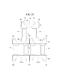
- the wave-dissipation / fish reef blocks 1 adjacent to each other in the horizontal direction are arranged so that the projecting bodies 32 at the four corners of each block are gathered at one point.
- the projecting body 32a of the wave-dissipating / fish reef block 1a, the projecting body 32b of the wave-dissipating / fish reef block 1b, and the wave-dissipating / fish reef block 1c The projecting body 32c and the projecting body 32d of the wave-dissipating / fish reef block 1d are combined to form one large convex portion 61.
- the protrusion 61 formed by combining the projecting bodies 32 is provided.
- the through-hole 11 of the wave-dissipating / reef block 1e is inserted.
- the four projecting bodies 33 projecting from the lower frame body 22 in the wave-dissipation / fish reef block 1e are inserted into the respective through holes 10 in the wave-dissipation / fish reef blocks 1a to 1d. .
- the wave-dissipating / fish reef block 1e When the wave-dissipating / fish reef block 1e is gradually pushed down in such a state, the through hole 11 of the wave-dissipating / fish reef block 1e is finally fitted into the convex portion 61, and As a result of the four projecting bodies 33 projecting downward from the lower frame body 22 being fitted into the respective through holes 10 in the wave-dissipating / fish reef blocks 1a-1d, the wave-dissipating / fish reef blocks 1a-1d The wave-dissipation / fish reef block 1e is firmly fixed to the upper stage.
- the taper 15 of the convex portion 61 formed by combining the four projecting bodies 32a to 32d and the taper 15 formed in the through hole 11 of the wave-dissipating / fish reef block 1e in the upper stage are brought into contact with each other. Slowly push the wave extinguishing / fish reef block 1e in the state where As a result, the taper 15 of the convex portion 61 and the taper 15 formed in the through hole 11 of the upper wave-dissipating / fish reef block 1e can guide each other. It becomes easy to match the approximate center of the hole 11.
- the taper 15 of the projecting bodies 33a to 33d in the upper wave-dissipation / fish reef block 1e is guided by the taper 15 of each through hole 10 in the wave-dissipation / fish reef block 1a to 1d.
- the other three wave-dissipating / fish reef block 1 projecting bodies 33 are inserted into the through holes 10 in the wave-dissipating / reef blocks 1a to 1d. .
- four projecting bodies 33 of the wave-dissipating / fish reef block 1 that are different from each other are inserted into the through-hole 10 and are respectively fitted to each other.
- the projecting bodies 33a to 33d of the wave-dissipating / fish reef block 1 are connected to the four through-holes of the four wave-dissipating / fish reef blocks 1 below. 10 is inserted. Further, the projecting bodies 32a to 32b of the wave-dissipating / fish reef block 1 are inserted into the through holes 11 of the four wave-dissipating / fish reef blocks 1 in the upper stage. In each through hole 10, 11, four projecting bodies 33, 32 of the wave-dissipating / fish reef block 1 adjacent to the upper side or the lower side are inserted and fitted.
- the lowermost block 1 and the uppermost block 1 of the stacked blocks 1 of each layer omit the configuration of the column body 31 or the plate-like body 40, and are flat blocks in which the upper frame body 21 and the lower frame body 22 are directly integrated. It is good. At this time, the protruding body 32 on the upper surface of the upper frame body 21 and the protruding body 33 on the lower surface of the lower frame body 22 may be omitted as necessary.
- this block layer absorbs the unevenness of the top surface of the base mount as a wave-dissipating / reef body substrate constructed by stacking wave-dissipating / reef blocks, By providing a foundation surface with less unevenness.
- protrusions of a cobblestone size are provided on the entire lower surface of the lower frame body 22 of the flat block so that the sliding friction resistance between the flat block lower surface and the mound surface is increased. Good.
- the upper part of the wave-dissipating block body is cast in place with a thickness of about 1 m.
- the above-mentioned flat block may be used as the uppermost layer of the wave-dissipating / fish reef body.
- the flat block layer becomes a weight of the wave-dissipating / fish reef body, and it is possible to improve the stability of the wave-dissipating / fish-reef body against waves.
- the protruding body 32 on the upper surface of the upper frame body 21 of the flat block may be omitted as necessary.
- hooks for lifting blocks are embedded in advance in the projecting bodies 32a to 32d at the four corners of the wave-dissipating / reef block 1.
- the hook is lifted by a crane or the like, and moved and hung, so that it can be set at a predetermined position.
- the block setting work is generally performed according to the instructions of the diver.
- a mark of the setting place in the fish reef block 1 it is desirable to attach a floating rope with a mark rope to a predetermined position on the upper surface of the existing wave-dissipating / fish reef block 1 in the water.
- the rope and the float may be colored so that they stand out even in water.
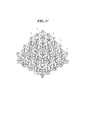
- FIG. 18 shows a configuration example of the lowest stage in assembling the wave-extinguishing / fish reef block 1 and a configuration example used when the outer edge walls of the wave-extinguishing / fish reef body are stacked vertically.
- a wave-dissipation / fish reef block 1f (for example, a corner block: having a size corresponding to 1.5 widths of the edge block) is used at the corner, and the wave-dissipation / fish reef block 1g at the edge.
- an edge block a size corresponding to 1.5 pieces of the length of the wave-dissipating / reef block 1 is used.
- the wave-dissipation / reef block 1 is shifted by half. In order to eliminate this shift, it is necessary to place blocks 1.5 times as long as the wave-dissipating / fish reef block 1 at the four corners of the block layer and at the edge of the outer periphery.
- the edge width of the layer using the edge block 1g at the outer peripheral edge is set to a width corresponding to one of the wave-dissipating / fish reef block 1, or one of the wave-dissipating / fish reef block 1 .5 or 2 widths, and every time several layers of the outer edge wall are stacked vertically, there will be a wave breakage. It becomes possible to make the outer edge gradient in assembling the reef block 1 gentle, steep or variably stacked.
- FIG. 19A is a plan view of the wave-dissipation / fish reef block 1f
- FIG. 19B is a side view of the wave-dissipation / fish reef block 1f.
- the wave-extinguishing / fish reef block 1f is provided with a protruding body 32e in which the four protruding bodies 32 are integrated, and a protruding body 32f in which the two protruding bodies 32 are integrated.
- FIG. 20 is a plan view of the wave-absorbing / fish reef block 1g.
- the wave extinguishing / fish reef block 1g is provided with a protruding body 32g in which the two protruding bodies 32 are integrated.
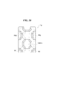
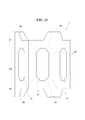
- FIG. 21 and 22 show examples in which the shape of the wave-dissipating / fish reef block 1 in a plan view is a regular hexagonal shape.
- FIG. 21 is a plan view
- FIG. 22 is a side view viewed from the M direction.
- each plate-like body 40 of the regular hexagonal column shaped wave-dissipating / fish reef block 1 is provided with a horizontal hole 41.
Landscapes
- Engineering & Computer Science (AREA)
- General Engineering & Computer Science (AREA)
- Life Sciences & Earth Sciences (AREA)
- Structural Engineering (AREA)
- Mechanical Engineering (AREA)
- Civil Engineering (AREA)
- Ocean & Marine Engineering (AREA)
- Environmental & Geological Engineering (AREA)
- Environmental Sciences (AREA)
- Marine Sciences & Fisheries (AREA)
- Zoology (AREA)
- Animal Husbandry (AREA)
- Biodiversity & Conservation Biology (AREA)
- Revetment (AREA)
- Artificial Fish Reefs (AREA)
Abstract
L'invention porte sur un bloc de récif pour poissons et d'absorption des vagues, lequel bloc est apte à la fois aux fonctions de récif pour poissons et d'absorption des vagues. Selon le bloc de récif pour poissons et d'absorption des vagues de la présente invention, qui est fermement relié sous l'eau par un ajustement et une accumulation de couches, un corps de bâti supérieur (12) et un corps de bâti inférieur (22) où des trous traversants (10, 11) sont formés presque dans un centre de ces deux derniers sont intégrés entre eux par l'utilisation d'un cylindre ou d'un corps en forme de plaque, et une pluralité de corps saillants (32, 33) font saillie à partir d'une partie de coin de chacun des corps de bâti (21, 22). Les corps saillants (33, 32) d'une pluralité d'autres blocs de récif pour poissons et d'absorption des vagues peuvent être insérés dans les trous traversants (10, 11) de chacun des corps de bâti (21, 22), et les corps saillants (32, 33) de chacun des corps de bâti (21, 22) peuvent être insérés dans les trous traversants (11, 10) d'un autre bloc de récif pour poissons et d'absorption des vagues.
Applications Claiming Priority (2)
| Application Number | Priority Date | Filing Date | Title |
|---|---|---|---|
| JP2011-054154 | 2011-03-11 | ||
| JP2011054154A JP4852175B1 (ja) | 2011-03-11 | 2011-03-11 | 消波・魚礁ブロック |
Publications (1)
| Publication Number | Publication Date |
|---|---|
| WO2012124254A1 true WO2012124254A1 (fr) | 2012-09-20 |
Family
ID=45540506
Family Applications (1)
| Application Number | Title | Priority Date | Filing Date |
|---|---|---|---|
| PCT/JP2012/000957 Ceased WO2012124254A1 (fr) | 2011-03-11 | 2012-02-14 | Bloc de récif pour poissons et d'absorption des vagues |
Country Status (2)
| Country | Link |
|---|---|
| JP (1) | JP4852175B1 (fr) |
| WO (1) | WO2012124254A1 (fr) |
Cited By (6)
| Publication number | Priority date | Publication date | Assignee | Title |
|---|---|---|---|---|
| JP2017008664A (ja) * | 2015-06-25 | 2017-01-12 | 株式会社チスイ | 消波ブロック |
| CN113100141A (zh) * | 2021-03-23 | 2021-07-13 | 大连海洋大学 | 一种生态荧光鱼礁 |
| USD1003461S1 (en) | 2021-01-22 | 2023-10-31 | Entreprises Bastech (2014) Inc. | Reef block |
| USD1014788S1 (en) | 2021-09-08 | 2024-02-13 | Entreprises Bastech (2014) Inc. | Reef block |
| USD1022254S1 (en) | 2021-10-21 | 2024-04-09 | Entreprises Bastech (2014) Inc. | Reef block |
| USD1098496S1 (en) | 2023-07-26 | 2025-10-14 | Entreprises Bastech (2014) Inc. | Reef block |
Families Citing this family (9)
| Publication number | Priority date | Publication date | Assignee | Title |
|---|---|---|---|---|
| JP4852175B1 (ja) * | 2011-03-11 | 2012-01-11 | 涌太郎 浅井 | 消波・魚礁ブロック |
| KR101211536B1 (ko) * | 2012-03-16 | 2012-12-12 | 주식회사 미래와바다 | 이단 삼각 인공 어초 및 그 배치 구조 |
| KR101206102B1 (ko) * | 2012-06-29 | 2012-11-28 | 심재덕 | 모래 유실방지 인공어초 |
| KR101406916B1 (ko) | 2013-12-02 | 2014-06-30 | 합자회사 대덕산업 | 모래 유실방지 인공어초의 시공방법 |
| CN108617564B (zh) * | 2018-08-30 | 2019-01-04 | 山东富瀚海洋科技有限公司 | 一种组合式人工鱼礁 |
| WO2020055980A1 (fr) | 2018-09-11 | 2020-03-19 | Coastal Environments, Incorporated | Appareil d'atténuation d'onde en béton et ensemble associé facilitant la formation d'un récif d'huître vertical et procédé de formation d'un récif d'huître vertical incorporant un ensemble d'appareils d'atténuation d'onde en béton |
| KR102350819B1 (ko) * | 2019-06-11 | 2022-01-12 | 장석걸 | 화로형 인공어초 |
| CN117546808A (zh) * | 2022-08-03 | 2024-02-13 | 青岛绿帆再生建材有限公司 | 一种基于碱渣资源化利用的人工鱼礁结构 |
| KR102881584B1 (ko) * | 2024-04-11 | 2025-11-06 | 리프알앤디센터 주식회사 | 유속저감형 사각 리프 블록 |
Citations (5)
| Publication number | Priority date | Publication date | Assignee | Title |
|---|---|---|---|---|
| GB2159190A (en) * | 1984-05-22 | 1985-11-27 | Vectis Stone Group Plc | Concrete block |
| JPH0169827U (fr) * | 1987-10-29 | 1989-05-09 | ||
| US5122015A (en) * | 1991-03-04 | 1992-06-16 | Shen Chen J | Construction assembly |
| JP2001241023A (ja) * | 2000-02-29 | 2001-09-04 | Mitani Sekisan Co Ltd | 魚礁兼用消波用ブロック |
| JP4852175B1 (ja) * | 2011-03-11 | 2012-01-11 | 涌太郎 浅井 | 消波・魚礁ブロック |
Family Cites Families (3)
| Publication number | Priority date | Publication date | Assignee | Title |
|---|---|---|---|---|
| US4083190A (en) * | 1976-05-10 | 1978-04-11 | Raul Pey | Fundamental armor module in breakwater net linked system |
| DE3728903C1 (de) * | 1987-08-29 | 1988-11-24 | Daimler Benz Ag | Kupplungsverzahnung einer sperrsynchronisierten Schaltkupplung insbesondere eines Gangwechselgetriebes mit von ihrer Welle abschaltbaren Zahnraedern |
| WO2010104342A2 (fr) * | 2009-03-11 | 2010-09-16 | 우암종합건설(주) | Brise-lames sous-marin poreux conçu pour empêcher l'érosion du littoral et former un fond de pêche, et procédé pour produire des blocs écologiques pour ce brise-lames sous-marin |
-
2011
- 2011-03-11 JP JP2011054154A patent/JP4852175B1/ja not_active Expired - Fee Related
-
2012
- 2012-02-14 WO PCT/JP2012/000957 patent/WO2012124254A1/fr not_active Ceased
Patent Citations (5)
| Publication number | Priority date | Publication date | Assignee | Title |
|---|---|---|---|---|
| GB2159190A (en) * | 1984-05-22 | 1985-11-27 | Vectis Stone Group Plc | Concrete block |
| JPH0169827U (fr) * | 1987-10-29 | 1989-05-09 | ||
| US5122015A (en) * | 1991-03-04 | 1992-06-16 | Shen Chen J | Construction assembly |
| JP2001241023A (ja) * | 2000-02-29 | 2001-09-04 | Mitani Sekisan Co Ltd | 魚礁兼用消波用ブロック |
| JP4852175B1 (ja) * | 2011-03-11 | 2012-01-11 | 涌太郎 浅井 | 消波・魚礁ブロック |
Cited By (6)
| Publication number | Priority date | Publication date | Assignee | Title |
|---|---|---|---|---|
| JP2017008664A (ja) * | 2015-06-25 | 2017-01-12 | 株式会社チスイ | 消波ブロック |
| USD1003461S1 (en) | 2021-01-22 | 2023-10-31 | Entreprises Bastech (2014) Inc. | Reef block |
| CN113100141A (zh) * | 2021-03-23 | 2021-07-13 | 大连海洋大学 | 一种生态荧光鱼礁 |
| USD1014788S1 (en) | 2021-09-08 | 2024-02-13 | Entreprises Bastech (2014) Inc. | Reef block |
| USD1022254S1 (en) | 2021-10-21 | 2024-04-09 | Entreprises Bastech (2014) Inc. | Reef block |
| USD1098496S1 (en) | 2023-07-26 | 2025-10-14 | Entreprises Bastech (2014) Inc. | Reef block |
Also Published As
| Publication number | Publication date |
|---|---|
| JP4852175B1 (ja) | 2012-01-11 |
| JP2012187060A (ja) | 2012-10-04 |
Similar Documents
| Publication | Publication Date | Title |
|---|---|---|
| JP4852175B1 (ja) | 消波・魚礁ブロック | |
| CN102359087B (zh) | 一种透空型潜堤 | |
| KR20120112878A (ko) | 방호 유니트 | |
| CN107059769B (zh) | 一种利用红树林和珊瑚分层消浪的海岸防护结构 | |
| US20110318105A1 (en) | Underwater breakwater for easily attenuating wave energy and method of manufacturing eco-friendly blocks for the same | |
| KR100898042B1 (ko) | 인공 리프와 이의 시공 방법 | |
| CN108432681A (zh) | 一种十字翼型人工鱼礁 | |
| KR200473630Y1 (ko) | 해양생태계 활성화를 위한 해중림 조성용 복합재질 콘크리트 블록 | |
| KR101056619B1 (ko) | 애쉬콘크리트가 충전된 강철원기둥 인공어초와 그 제조방법 | |
| CN202064320U (zh) | 一种浮式防波构件及由其拼接而成的防波堤 | |
| KR101063976B1 (ko) | 에코리프블록 | |
| JP5475480B2 (ja) | 水中設置構造物 | |
| KR100996879B1 (ko) | 패류 부착구조를 갖는 강재골조 인공어초 | |
| CN207969556U (zh) | 人工鱼礁底座及人工鱼礁 | |
| JP2011069052A (ja) | 人工海底山脈 | |
| KR100820628B1 (ko) | 인공어초를 겸비한 방파제용 소파블록 및 이의 시공방법 | |
| KR101082410B1 (ko) | 인공어초 형성 또는 침식과 모래 유실의 원인인 파랑 에너지 저감을 위한 해양 구조물 단위 모듈 | |
| JP2005054451A (ja) | 立体的歯合ブロック | |
| KR102733628B1 (ko) | 복합형 앵커블록 | |
| KR100977533B1 (ko) | 인공 어초 | |
| KR101011766B1 (ko) | 다면체 인공어초 | |
| US20260043207A1 (en) | Shoreline habitation constructions units, structures made therefrom and uses thereof | |
| JP2015113656A (ja) | 防波ブロック及び防波ブロック構造体及びその構築方法 | |
| KR101385506B1 (ko) | 버섯구조의 테트라포드 | |
| KR20150065033A (ko) | 소파블록 |
Legal Events
| Date | Code | Title | Description |
|---|---|---|---|
| 121 | Ep: the epo has been informed by wipo that ep was designated in this application |
Ref document number: 12757776 Country of ref document: EP Kind code of ref document: A1 |
|
| NENP | Non-entry into the national phase |
Ref country code: DE |
|
| 122 | Ep: pct application non-entry in european phase |
Ref document number: 12757776 Country of ref document: EP Kind code of ref document: A1 |