WO2012124346A2 - Vehicle seat vertical position adjustment apparatus - Google Patents
Vehicle seat vertical position adjustment apparatus Download PDFInfo
- Publication number
- WO2012124346A2 WO2012124346A2 PCT/JP2012/001843 JP2012001843W WO2012124346A2 WO 2012124346 A2 WO2012124346 A2 WO 2012124346A2 JP 2012001843 W JP2012001843 W JP 2012001843W WO 2012124346 A2 WO2012124346 A2 WO 2012124346A2
- Authority
- WO
- WIPO (PCT)
- Prior art keywords
- latch
- lifting
- lowering
- link
- input member
- Prior art date
- Legal status (The legal status is an assumption and is not a legal conclusion. Google has not performed a legal analysis and makes no representation as to the accuracy of the status listed.)
- Ceased
Links
Images







Classifications
-
- B—PERFORMING OPERATIONS; TRANSPORTING
- B60—VEHICLES IN GENERAL
- B60N—SEATS SPECIALLY ADAPTED FOR VEHICLES; VEHICLE PASSENGER ACCOMMODATION NOT OTHERWISE PROVIDED FOR
- B60N2/00—Seats specially adapted for vehicles; Arrangement or mounting of seats in vehicles
- B60N2/02—Seats specially adapted for vehicles; Arrangement or mounting of seats in vehicles the seat or part thereof being movable, e.g. adjustable
- B60N2/04—Seats specially adapted for vehicles; Arrangement or mounting of seats in vehicles the seat or part thereof being movable, e.g. adjustable the whole seat being movable
- B60N2/16—Seats specially adapted for vehicles; Arrangement or mounting of seats in vehicles the seat or part thereof being movable, e.g. adjustable the whole seat being movable height-adjustable
-
- B—PERFORMING OPERATIONS; TRANSPORTING
- B60—VEHICLES IN GENERAL
- B60N—SEATS SPECIALLY ADAPTED FOR VEHICLES; VEHICLE PASSENGER ACCOMMODATION NOT OTHERWISE PROVIDED FOR
- B60N2/00—Seats specially adapted for vehicles; Arrangement or mounting of seats in vehicles
- B60N2/02—Seats specially adapted for vehicles; Arrangement or mounting of seats in vehicles the seat or part thereof being movable, e.g. adjustable
- B60N2/04—Seats specially adapted for vehicles; Arrangement or mounting of seats in vehicles the seat or part thereof being movable, e.g. adjustable the whole seat being movable
- B60N2/16—Seats specially adapted for vehicles; Arrangement or mounting of seats in vehicles the seat or part thereof being movable, e.g. adjustable the whole seat being movable height-adjustable
- B60N2/1605—Seats specially adapted for vehicles; Arrangement or mounting of seats in vehicles the seat or part thereof being movable, e.g. adjustable the whole seat being movable height-adjustable characterised by the cinematic
- B60N2/161—Rods
- B60N2/1615—Parallelogram-like structure
-
- B—PERFORMING OPERATIONS; TRANSPORTING
- B60—VEHICLES IN GENERAL
- B60N—SEATS SPECIALLY ADAPTED FOR VEHICLES; VEHICLE PASSENGER ACCOMMODATION NOT OTHERWISE PROVIDED FOR
- B60N2/00—Seats specially adapted for vehicles; Arrangement or mounting of seats in vehicles
- B60N2/02—Seats specially adapted for vehicles; Arrangement or mounting of seats in vehicles the seat or part thereof being movable, e.g. adjustable
- B60N2/04—Seats specially adapted for vehicles; Arrangement or mounting of seats in vehicles the seat or part thereof being movable, e.g. adjustable the whole seat being movable
- B60N2/16—Seats specially adapted for vehicles; Arrangement or mounting of seats in vehicles the seat or part thereof being movable, e.g. adjustable the whole seat being movable height-adjustable
- B60N2/1605—Seats specially adapted for vehicles; Arrangement or mounting of seats in vehicles the seat or part thereof being movable, e.g. adjustable the whole seat being movable height-adjustable characterised by the cinematic
- B60N2/161—Rods
- B60N2/162—Scissors-like structure
-
- B—PERFORMING OPERATIONS; TRANSPORTING
- B60—VEHICLES IN GENERAL
- B60N—SEATS SPECIALLY ADAPTED FOR VEHICLES; VEHICLE PASSENGER ACCOMMODATION NOT OTHERWISE PROVIDED FOR
- B60N2/00—Seats specially adapted for vehicles; Arrangement or mounting of seats in vehicles
- B60N2/02—Seats specially adapted for vehicles; Arrangement or mounting of seats in vehicles the seat or part thereof being movable, e.g. adjustable
- B60N2/04—Seats specially adapted for vehicles; Arrangement or mounting of seats in vehicles the seat or part thereof being movable, e.g. adjustable the whole seat being movable
- B60N2/16—Seats specially adapted for vehicles; Arrangement or mounting of seats in vehicles the seat or part thereof being movable, e.g. adjustable the whole seat being movable height-adjustable
- B60N2/18—Seats specially adapted for vehicles; Arrangement or mounting of seats in vehicles the seat or part thereof being movable, e.g. adjustable the whole seat being movable height-adjustable the front or the rear portion of the seat being adjustable, e.g. independently of each other
-
- B—PERFORMING OPERATIONS; TRANSPORTING
- B60—VEHICLES IN GENERAL
- B60N—SEATS SPECIALLY ADAPTED FOR VEHICLES; VEHICLE PASSENGER ACCOMMODATION NOT OTHERWISE PROVIDED FOR
- B60N2/00—Seats specially adapted for vehicles; Arrangement or mounting of seats in vehicles
- B60N2/02—Seats specially adapted for vehicles; Arrangement or mounting of seats in vehicles the seat or part thereof being movable, e.g. adjustable
- B60N2/04—Seats specially adapted for vehicles; Arrangement or mounting of seats in vehicles the seat or part thereof being movable, e.g. adjustable the whole seat being movable
- B60N2/16—Seats specially adapted for vehicles; Arrangement or mounting of seats in vehicles the seat or part thereof being movable, e.g. adjustable the whole seat being movable height-adjustable
- B60N2/18—Seats specially adapted for vehicles; Arrangement or mounting of seats in vehicles the seat or part thereof being movable, e.g. adjustable the whole seat being movable height-adjustable the front or the rear portion of the seat being adjustable, e.g. independently of each other
- B60N2/1807—Seats specially adapted for vehicles; Arrangement or mounting of seats in vehicles the seat or part thereof being movable, e.g. adjustable the whole seat being movable height-adjustable the front or the rear portion of the seat being adjustable, e.g. independently of each other characterised by the cinematic
- B60N2/181—Rods
-
- B—PERFORMING OPERATIONS; TRANSPORTING
- B60—VEHICLES IN GENERAL
- B60N—SEATS SPECIALLY ADAPTED FOR VEHICLES; VEHICLE PASSENGER ACCOMMODATION NOT OTHERWISE PROVIDED FOR
- B60N2/00—Seats specially adapted for vehicles; Arrangement or mounting of seats in vehicles
- B60N2/02—Seats specially adapted for vehicles; Arrangement or mounting of seats in vehicles the seat or part thereof being movable, e.g. adjustable
- B60N2/04—Seats specially adapted for vehicles; Arrangement or mounting of seats in vehicles the seat or part thereof being movable, e.g. adjustable the whole seat being movable
- B60N2/16—Seats specially adapted for vehicles; Arrangement or mounting of seats in vehicles the seat or part thereof being movable, e.g. adjustable the whole seat being movable height-adjustable
- B60N2/18—Seats specially adapted for vehicles; Arrangement or mounting of seats in vehicles the seat or part thereof being movable, e.g. adjustable the whole seat being movable height-adjustable the front or the rear portion of the seat being adjustable, e.g. independently of each other
- B60N2/1807—Seats specially adapted for vehicles; Arrangement or mounting of seats in vehicles the seat or part thereof being movable, e.g. adjustable the whole seat being movable height-adjustable the front or the rear portion of the seat being adjustable, e.g. independently of each other characterised by the cinematic
- B60N2/1839—Seats specially adapted for vehicles; Arrangement or mounting of seats in vehicles the seat or part thereof being movable, e.g. adjustable the whole seat being movable height-adjustable the front or the rear portion of the seat being adjustable, e.g. independently of each other characterised by the cinematic pivoting about an axis located in an intermediate position
Definitions
- the present invention relates to a vehicle seat vertical position adjustment apparatus which lifts and lowers a vehicle seat by a back-and-forth lifting/lowering operation of an input member (controlling member).
- Devices for lifting and lowering a vehicle seat are roughly classified into a motor-operated type and a manual type.
- a manual type the lifting/lowering mechanism body and the input member are mounted entirely onto the outer surface of a lower bracket of the vehicle seat.
- the present invention has been devised in view of the awareness of the above described issues, and an object of the present invention is to provide a vehicle seat vertical position adjustment apparatus, wherein the space around the lower bracket of the seat is efficiently utilized, and the possibility of the adjustment apparatus interfering with other members (other mechanisms) is low and wherein a sufficient space can be provided for the lifting/lowering mechanism itself.
- the present invention has been accomplished by reexamining the technical common sense that states that the seat lifting/lowering mechanism and the input member should be arranged entirely on the outer surface of a lower bracket, and finding that the dead space under the seat cushion can be efficiently utilized and the design flexibility of the lifting/lowering mechanism itself can be improved with no interference with other members (other mechanisms) positioned on the outer surface of the lower bracket if the lifting/lowering mechanism body is arranged on the inner side of the lower bracket while the input member is positioned on the outer side of the lower bracket.
- a hand-operated type of vehicle seat vertical position adjustment apparatus is provided, as a basic structure, with a lifting/lowering link which is pivoted at one end and the other end thereof to a lower bracket of a vehicle seat and a vehicle floor, respectively; an input member which is supported by the vehicle seat and capable of being operated up and down; and a lifting/lowering mechanism which is driven in association with a lifting/lowering operation of the input member to lift and lower the lower bracket together with a rotational motion of the lifting/lowering link.
- the present invention is characterized by the lifting/lowering link, the input member and the lifting/lowering mechanism being supported by an inner side of the lower bracket, a through-hole formed in the lower bracket, and the input member being installed to extend to an outer side of the lower bracket from the inner side thereof through the through-hole so that a control portion of the input member is positioned on the outer surface of the lower bracket.
- the input member includes an inner input member, an outer input member and a joining member.
- the inner input member is provided with an inner arm freely rotatable about a control shaft and extending along an inner side of the lower bracket, and an outer connecting arm that is bent with respect to the inner arm, an outer input member is provided with a control portion that extends along the outer surface of the lower bracket and an inner connecting arm that is bent with respect to the control portion, and the outer connecting arm of the inner input member and the inner connecting arm of the outer input member are joined to each other by the joining member.
- This structure improves the strength of the input member (the joined portion between the outer connecting arm and the inner connecting arm).
- the joining member is configured of, e.g., a semi-cylindrical member, a radial-direction cut section of which is joined to the inner connecting arm of the outer input member, and the outer connecting arm of the inner input member is inserted into the semi-cylindrical member to be connected thereto.
- This structure gives the joined portion a box shape in cross section, thus making it possible to achieve a further improvement in strength.
- the present invention is equipped with a torsion spring which acts on at least one of the outer connecting arm of the inner input member and the inner connecting arm of the outer input member to hold the input member in a neutral position. Since the biasing force of the torsion spring acts at a position away from the control shaft (position at which the arm length is secured), the biasing force of the torsion spring can be small. As a consequence, miniaturization of the torsion spring can be achieved and the thickness of the vehicle seat vertical position adjustment apparatus can be reduced.
- this torsion spring be supported by a spring shaft that is provided separately from the control shaft and that the distance between the outer connecting arm and the spring shaft be set smaller than the distance between the outer connecting arm and the control shaft. If the torsion spring is supported by the spring shaft that is provided separately from the control shaft, the spring can be miniaturized, which makes it possible to reduce the thickness of the lifting/lowering mechanism. In addition, the operational resistance (operating force) to the input member can be freely set. By setting the distance between the outer connecting arm and the spring shaft shorter than the distance between the outer connecting arm and the control shaft, the biasing force of the torsion spring can be made smaller than that in the case where the torsion spring is supported by the control shaft.
- the shaft which supports the torsion spring is closer to the position (the outer connecting arm) where the biasing force of the torsion spring acts, which makes it possible to shorten both legs of the torsion spring, thus making miniaturization of the spring possible; moreover, the application of the biasing force becomes effective.
- the vehicle seat vertical position adjustment apparatus be further provided with a support plate, one end of which is supported by the control shaft and another end of which is joined to the outer connecting arm of the inner input member.
- the lifting/lowering link, the input member and the lifting/lowering mechanism are supported by a base plate which is composed of a member other than the lower bracket, and the base plate is fixed to the inner surface of the lower bracket.
- the space around the lower bracket of the vehicle seat can be efficiently utilized and the design flexibility of the lifting/lowering mechanism itself can be improved because the lifting/lowering mechanism and the input member are made to be linked with each other via a through-hole formed through the lower bracket by positioning the lifting/lowering mechanism on an inner side of the lower bracket while positioning the input member on an outer side of the lower bracket.
- FIG. 1 is a perspective view of an embodiment of a stepped lifting apparatus of a vehicle to which a vehicle seat vertical position adjustment apparatus according to the present invention has been applied in a state before the stepped lifting apparatus is installed to a lower bracket;
- FIG. 2 is a side view of the stepped lifting apparatus according to the present invention;
- FIG. 3 is an exploded perspective view of an embodiment of a portion of the stepped lifting apparatus according to the present invention which is positioned around a geared link of the stepped lifting apparatus;
- FIG. 4 is a perspective view of the stepped lifting apparatus according to the present invention in an assembled state;
- FIG. 5 is a sectional view taken along the line V-V shown in FIG. 2 in the same assembled state;
- FIG. 6 is a sectional view taken along the line VI-VI line shown in FIG. 2 in the same assembled state of the stepped lifting apparatus
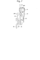
- FIG. 7 is a sectional view taken along the line VII-VII line shown in FIG. 2 in the same assembled state of the stepped lifting apparatus
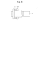
- FIG. 8 is a sectional view taken along the line VIII-VIII line shown in FIG. 2 in the same assembled state
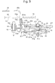
- FIG. 9 is a sectional view taken along the line IX-IX line shown in FIG. 2 in the same assembled state
- FIG. 10 is a sectional view taken along the line X-X line shown in FIG. 2 in the same assembled state
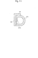
- FIG. 11 is a sectional view taken along the line XI-XI line shown in FIG.
- FIG. 12 is an enlarged side view of a friction gear and a friction latch which constitute a friction mechanism of the same stepped lifting apparatus
- FIG. 13 is a side view of the same stepped lifting apparatus, showing a locked state (initial position) thereof at a specific height position
- FIG. 14 is a side view of the same vehicle seat vertical position adjustment apparatus, showing the first phase of a lifting operation thereof
- FIG. 15 is a side view showing the second phase of the same lifting operation
- FIG. 16 is a side view showing the third phase of the same lifting operation
- FIG. 17 is a side view showing the fourth phase (return-to-initial-position phase) of the same lifting operation
- FIG. 18 is a side view of the same stepped lifting apparatus, showing a locked state (initial position) thereof at a specific height position;
- FIG. 19 is a side view of the same stepped lifting apparatus, showing the first phase of a lowering operation thereof;
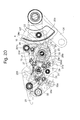
- FIG. 20 is a side view showing the second phase of the same lowering operation;
- FIG. 21 is a side view showing the third phase of the same lowering operation;
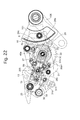
- FIG. 22 is a side view showing the fourth phase (return-to-initial-position phase) of the same lowering operation;
- FIG. 23 is a side view of the same stepped lifting apparatus, showing a locked state (initial position) thereof at a specific height position.
- FIGS. 1 and 4 are perspective views of the embodiment of the stepped lifting apparatus in different states
- FIG. 2 is a side view of the stepped lifting apparatus
- FIG. 3 is an exploded perspective view of the stepped lifting apparatus.
- a lifting/lowering link 10X and a geared link 10T are integrally joined to a shaft 11, which is rotatably supported by a base plate (ascending/descending body) 13 that is fixed to an inner side 51 of a lower bracket 50 by which a seat (seat cushion) is supported, at different positions in the axial direction of the shaft 11, and the lower end of the lifting/lowering link 10X is pivoted on a floor bracket (base) 14 integral with a floor via a shaft 12. Accordingly, if the geared link 10T swings about the shaft 11, the lifting/lowering link 10X swings about the shaft 11 while the base plate 13 moves up and down relative to the base 14.
- the present embodiment is an embodiment which lifts and lowers the base plate 13 by swinging the geared link 10T forward and reverse.
- a link pinion 15 which is positioned on a circular arc about the shaft 11 and a link ratchet 16 which is smaller in diameter than the link pinion 15 are formed integral with the geared link 10T that is pivoted on the base plate 13 via the shaft 11.
- a circular arc guide 10P which is centered about the shaft 11 is formed through the geared link 10T, and a guide pin 10Q, both ends of which are respectively fixed to the base plate 13 and a second auxiliary bracket 18, is engaged in the circular arc guide 10P to be freely movable relative thereto.
- a shaft 21 is rotatably supported by the base plate 13 (which is a member with the shaft 11 that serves as a center of the circular arc (base circle) of the link pinion 15 and the link ratchet 16) thereon via first and second auxiliary brackets 17 and 18 that are respectively fixed to the back and the front of the base plate 13.
- Serrated portions 21a and 21b and a square shaft portion 21c are formed on the shaft 21 between both ends thereof that are freely rotatably supported by the first and second auxiliary brackets 17 and 18, respectively (FIG. 6).
- An input pinion 22 which is in mesh with the link pinion 15 of the geared link 10T is coaxially and integrally connected to the serrated portion 21a (to be irrotatable relative to the serrated portion 21a).
- a bidirectional-motion transmission ratchet 23 is coaxially and integrally connected to the serrated portion 21b (to be irrotatable relative to the serrated portion 21b).
- a friction gear 30 is coaxially and integrally connected to the square shaft portion 21c (to be irrotatable relative to the square shaft portion 21c).
- a round shaft portion 21d which is inserted into a shaft hole of the base plate 13 to be freely rotatable relative to the base plate 13, and a flange portion 21e, which comes in contact with the base plate 13 to define the position of the shaft 21 in the axial direction thereof, are formed between the serrated portions 21a and 21b of the shaft 21; a round shaft portion 21f is formed on the outer of the serrated portion 21a while a round shaft portion 21g is formed between the serrated portion 21b and the square shaft portion 21c.
- a retaining nut and a washer are fitted to both ends of the shaft 21, respectively (FIG. 6).
- a first auxiliary lever (inner input member) 201 is positioned between the base plate 13 and the first auxiliary bracket 17, a second auxiliary lever (support plate) 204 is positioned on the outer side of the second auxiliary bracket 18, and the first and second auxiliary levers 201 and 204 are respectively supported by the round shaft portions 21g and 21f of the shaft 21 to be freely rotatable relative to each other.
- the first auxiliary lever 201 is provided with an inner arm 201a which extends along an inner surface of the base plate 13, and an outer connecting arm 201b which is formed by bending the free end of the inner arm 201 in a direction to pass through a circular arc opening 13a1 that is formed through the base plate 13, and the outer connecting arm 201b passes through a through-hole 204a formed in the second auxiliary lever 204 on the free end side thereof (FIG. 9).
- the first auxiliary lever 201 and the second auxiliary lever 204 are connected via a connecting link pin 205 which extends through a circular arc opening 13a2 formed through the base plate 13, and the first auxiliary lever 201 and the second auxiliary lever 204 normally rotate as one body about the shaft 21.
- the second auxiliary lever 204 constitutes a support plate, one end of which is supported by the shaft (control shaft) 21 and the other end of which is connected to the outer connecting arm 201b of the first auxiliary lever (inner input member) 201.
- a control lever 20 is joined to the first auxiliary lever 201.
- the control lever 20 is provided with a control (operating) portion (outer arm) 20a which extends along an outer surface 52 of the lower bracket 50, and an inner connecting arm 20b which is formed by bending the control lever 20 inwardly at the rear end of the control portion 20a in a substantially orthogonal direction to pass through a through-hole (circular arc hole) 50a of the lower bracket 50, and the inner connecting arm 20b is made to overlap the outer connecting arm 201b of the first auxiliary arm 201 and to be joined integrally thereto via a semi-cylindrical member (joining member) 203 (FIG. 9).
- the semi-cylindrical member 203 is joined, at both ends of a radial-direction cut section thereof, to the flat inner connecting arm 20b, and the outer connecting arm 201b is positioned inside the semi-cylindrical member 203 and joined thereat. Since the flat inner connecting arm 20b and the outer connecting arm 201b are joined to each other via the semi-cylindrical member 203, the joined portion has a box shape in cross section, thus having an improved strength.
- the flat inner connecting arm 20b is provided with an angled portion 20c which bends at a substantially right angle relative to the inner connecting arm 20b, and the angled portion 20c is made to abut against an outer surface of the semi-cylindrical member 203 to be fixed thereto (see FIGS. 1 and 11). With this structure, the strength of the joined portion has been further improved.
- the above-described control lever 20, the first auxiliary lever 201 and the second auxiliary lever 204 together constitute an input member which swings about the shaft 21.
- the first auxiliary lever 201 which includes the inner arm 201a and the outer connecting arm 201b, constitutes an inner input member
- the control lever 20, which includes the control portion 20a and the inner connecting arm 20b constitutes an outer input member.
- the control lever 20 is normally held in a neutral position by a neutral position return spring (torsion spring) 19.
- a neutral position return spring tilt spring
- the central coiled portion of the neutral position return spring 19 is fitted on a spring shaft 192 that is fixed to the base plate 13, and legs 19a and 19b of the neutral position return spring 19 are respectively engaged with the outer connecting arm 201b of the first auxiliary lever 201 and a spring hook projection 13c projected from the base plate 13 in a manner to hold the outer connecting arm 201b and the spring hook projection 13c.
- the neutral position return spring 19 holds the control lever 20 in the neutral position in a state where no operating force is exerted on the control lever 20.
- the neutral position return spring 19 brings the control lever 20 back to the neutral position upon the operating force, which moves the control lever 20 up or down, being released.
- the distance between the spring shaft 192 and the outer connecting arm 201b is smaller than the distance between the outer connecting arm 201b and the shaft 21 (see FIG. 9).
- the spring shaft 192 is a cylindrical member and installed with a fixing bolt 191 for fixing the base plate 13 to the lower bracket 50 and extends through the hollow portion of the spring shaft 192.
- An upward-directional motion transmission latch (hereinafter referred to as up-latch) 27 and a downward-directional motion transmission latch (hereinafter referred to as down-latch) 28 that are provided as a pair which are selectively engaged with the bidirectional-motion transmission ratchet 23 are pivoted on the first auxiliary lever 201 about a shaft 27a and a shaft 28a, respectively.
- the up-latch 27 and the down-latch 28 are symmetrically arranged with respect to the upper and lower tooth surfaces of the bidirectional-motion transmission ratchet 23 and are provided at the ends thereof with tooth engaging pawls 27b and 28b and are also provided at intermediate portions thereof with forced-release pins 27c and 28c, respectively.
- a torsion spring 278 which rotationally moves and biases the up-latch 27 and the down-latch 28 in directions to make the tooth engaging pawls 27b and 28b engaged with teeth 23a of the bidirectional-motion transmission ratchet 23, respectively, is inserted between the forced-release pins 27c and 28c.
- the central coiled portion of the torsion spring 278 is fitted on the connecting link pin 205.
- the forced-release pin (control pin) 27c of the up-latch 27 and the forced-release pin (control pin) 28c of the down-latch 28 are engaged in position-limit cam holes (control cam grooves) 270 and 280, respectively, which are formed in the base plate 13.
- the position-limit cam holes 270 and 280 come in contact with the forced-release pin 27c and the forced-release pin 28c to hold the up-latch 27 and the down-latch 28 in engagement standby positions thereof in which the up-latch 27 and the down-latch 28 standby to be engaged with the bidirectional-motion transmission ratchet 23, respectively, when the control lever 20 is in the neutral position or a position in the vicinity thereof (see FIGS. 13, 18 and 23).
- the control lever 20, the up-latch 27 and the bidirectional-motion transmission ratchet 23 constitute a lifting mechanism which makes the geared link 10T swing in the lifting direction via the link pinion 15 to lift the base plate 13 stepwise every time the control lever 20 is operated to the lifted position from the neutral position
- the control lever 20, the down-latch 28 and the bidirectional-motion transmission ratchet 23 constitute a lowering mechanism which makes the geared link 10T swing in the lowering direction via the link pinion 15 to lower the base plate 13 stepwise every time the control lever 20 is operated to the lowered position from the neutral position.
- the forced-release pin 27c of the up-latch 27 and the position-limit cam hole (control cam groove) 270 and the forced-release pin 28c of the down-latch 28 and the position-limit cam hole (control cam groove) 280 described above constitute a latch control mechanism which releases the engagement between the tooth engaging pawl 28b of the down-latch 28 and the teeth 23a of the bidirectional-motion transmission ratchet 23 and rotates the geared link 10T in the lifting direction via the engagement between the tooth engaging pawl 27b of the up-latch 27 and the teeth 23a of the bidirectional-motion transmission ratchet 23 every time the control lever 20 is operated to the lifted position from the neutral position and which releases the engagement between the tooth engaging pawl 27b of the up-latch 27 and the teeth 23a of the bidirectional-motion transmission ratchet 23 and rotates the geared link 10T in the lowering direction via the engagement between the tooth engaging pawl 27b of the down-latch 28 and the teeth 23a of the bidirectional-motion transmission ratchet
- the up-latch 27 and the down-latch 28 slip with respect to the bidirectional-motion transmission ratchet 23 (FIGS. 17 and 22). Accordingly, regardless of the lifting/lowering operational direction of the control lever 20 from the neutral position, the base plate 13 is normally lifted or lowered when the up-latch 27 or the down-latch 28 rotates the input pinion 22 via the bidirectional-motion transmission ratchet 23. Up/down motion of the base plate 13 is always accompanied by a swing motion of the control lever 20.
- a first lowering prevention latch 24 which is engaged with the link ratchet 16 is pivoted by a shaft 46 between the base plate 13 and the second auxiliary bracket 18.
- a tooth engaging pawl (tip pawl/ engaging pawl) 24c which is engaged with and disengaged from the link ratchet 16 is formed at the tip of the first lowering prevention latch 24.
- a latch biasing spring (torsion spring) 46a is inserted onto the shaft 46 between the first lowering prevention latch 24 and the base plate 13.
- the latch biasing spring 46a rotates and biases the first lowering prevention latch 24 in a direction to make the tooth engaging pawl 24c engaged with teeth of the link ratchet 16.
- the tooth engaging pawl 24c is in mesh with the link ratchet 16 (FIGS. 2, 13, 18 and 23).
- the first lowering prevention latch 24 and the link ratchet 16 constitute a unidirectional rotation-allowance stepped stopper mechanism which allows the link ratchet 16 to swing by allowing the tooth engaging pawl 24c ride over the teeth of the link ratchet 16 against the force of the latch biasing spring 46a when the geared link 10T swings about the shaft 11 in the lifting direction (the counterclockwise direction with respect to FIG. 2) and which prevents the link ratchet 16 from rotating by making the tooth engaging pawl 24c engaged with teeth of the link ratchet 16 when the geared link 10T attempts to swing reversely in the lowering direction (the clockwise direction with respect to FIG. 2). Specifically, the link ratchet 16 attempts to rotate in the clockwise direction with respect to FIG.
- a forced-release pin 24d is embedded in a side (back surface) of the first lowering prevention latch 24.
- a forced-release projection 201c which is engaged with the forced-release pin 24d of the first lowering prevention latch 24 to release the engagement between the first lowering prevention latch 24 and the link ratchet 16 when the first auxiliary lever 201 is operated downwardly from the neutral position, is formed on the first auxiliary lever 201.
- the link ratchet 16, the first lowering prevention latch 24, the forced-release pin 24d and the forced-release projection 201c of the first auxiliary lever 201 constitute a first lowering prevention latch mechanism which prevents the geared link 10T from swinging downward when the control lever 20 is in the neutral position and which allows the geared link 10T to swing downward when the control lever 20 is operated in the lowering direction.
- a second lowering prevention latch 25 is pivoted about the shaft 21 on the base plate 13 (the auxiliary brackets 17 and 18) to be freely rotatable relative to the control lever 20.
- a tooth engaging pawl (tip pawl/ engaging pawl) 25b is formed at one end of the second lowering prevention latch 25 with the shaft 21 positioned between each end of the second lowering prevention latch 25, a position limit surface 25c which comes in contact with the connecting link pin 205 is formed at the other end of the second lowering prevention latch 25, and the position limit surface 25c of the second lowering prevention latch 25 is biased in a direction to come in contact with the connecting link pin 205 by a latch biasing spring (torsion spring) 59 which is inserted in between the second lowering prevention latch 25 and the connecting link pin 205 (the first auxiliary lever 201) to be spring-connected to the connecting link pin 205.
- the connecting link pin 205 is configured to come in contact with the position limit surface 25c of the second lowering prevention latch 25, which is spring-connected to the connecting link pin 205 by the latch biasing spring 59, so that the second lowering prevention latch 25 follows (is associated with) the movement of the control lever 20.
- the second lowering prevention latch 25 is held in a non-engaging position in which the tooth engaging pawl 25b is disengaged from the link ratchet 16.
- Operating the control lever 20 in the lowering direction from the neutral position causes the second lowering prevention latch 25 to rotate in a direction toward the link ratchet to make the tooth engaging portion 25b and the link ratchet 16 either come in contact with each other or engaged with each other.
- the friction gear 30, which is connected to the shaft 21 and is irrotatable relative to the shaft 21, is provided on an outer peripheral surface of the friction gear 30 with friction teeth 30a which are formed at a constant pitch, and a tip friction pawl 31b of a friction latch (friction lever) 31 that is pivoted on the base plate 13 via the shaft 34 is engaged with the friction teeth 30a.
- the friction latch 31 is provided, on the opposite side from the tip friction pawl 31b with the shaft 34 positioned between both ends of the friction latch 31, with a stopper arm 31c, and the base plate 13 is provided with a stopper 13d having a semi-cylindrical cross sectional shape which can come into contact with the stopper arm 31c.
- a torsion spring 32 which is installed on a pin 32a fixed to the base plate 13 is hooked between a spring hook projection 31e formed at an end of the stopper arm 31c and a spring hook projection 13b of the base plate 13 to rotate and bias the friction latch 31 in a direction to make the tip friction pawl 31b engaged with the friction teeth 30a.
- the stopper arm 31c is provided with a shock-absorbing projection 31d, a shock-absorbing member 311 is fitted on the semi-cylindrical stopper 13d, and the friction latch 31 is prevented from rotating toward the friction gear 30 at a position where the shock-absorbing projection 31d of the stopper arm 31c comes in contact with the shock-absorbing member 311.
- the tip friction pawl 31b of the friction latch 31 does not come in contact with the bottom of the friction teeth 30a at a position where the shock-absorbing projection 31d and the shock-absorbing member 311 are in contact with each other.
- a gap S exists between the tip friction pawl 31b and the bottom of the friction teeth 30a.
- the shock-absorbing member 311 is made of a material softer than the friction latch 31 (the stopper arm 31c and the shock-absorbing projection 31d), e.g., a synthetic resin material (low-rebound material). Forming the shock-absorbing member 311 into a semicircular shape in cross section makes it possible to reduce the surface pressure upon the shock-absorbing projection 31d abutting against the shock-absorbing member 311 and to suppress the occurrence of impact noise.
- Each tooth of the friction teeth 30a is provided with a lifting sliding-contact surface 30a1 and a lowering sliding-contact surface 30a2 which are alternately arranged on the friction teeth 30a, wherein the tip friction pawl 31b comes in sliding contact with the lifting sliding-contact surface 30a1 when the friction gear 30 rotates in the lifting direction (when the base plate 13 moves up) and the tip friction pawl 31b comes in sliding contact with the lowering sliding-contact surface 30a2 when the friction gear 30 rotates in the lowering direction.
- the lowering sliding-contact surface 30a2 is greater in length than the lifting sliding-contact surface 30a1.
- the position of the friction latch 31 is controlled via the control lever 20, the first auxiliary lever 201 and a friction latch control link 33 which is pivoted about the connecting link pin 205.
- the connecting link pin 205 projects from the first auxiliary lever 201, and the friction latch 31 is provided with a link pin 31a which is fixed between the shaft 34 and the spring hook projection 31e.
- the link pin 31a is engaged in an elongated hole 33a, which is formed in the friction latch control link 33 and elongated in the radial direction thereof, so that the swing operation of the first auxiliary lever 201 is transmitted to the friction latch 31.
- the friction latch 31 When the control lever 20 (the first auxiliary lever 201) is in the neutral position, the friction latch 31 is held in a position in which the shock-absorbing projection 31d is in contact with the shock-absorbing member 311 while the tip friction pawl 31b is engaged with the friction teeth 30a by the rotational biasing force of the torsion spring 32.
- Operating the control lever 20 in the lifting direction from the neutral position causes the tip end face of the elongated hole 33a of the friction latch control link 33 to come into contact with and pull the link pin 31a to cause the friction latch 31 to rotate in a direction to disengage the tip friction pawl 31b from the friction teeth 30a.
- the friction latch 31 rotates in a direction to make the tip friction pawl 31b engaged with the friction teeth 30a by the biasing force of the torsion spring 32.
- the shock-absorbing projection 31d comes into contact with the shock-absorbing member 311 to thereby brake the friction latch 31, so that the tip friction pawl 31b stops with the gap S remaining between the tip friction pawl 31b and the bottom of the friction teeth 30a. Consequently, no impact or impact noise occurs because the tip friction pawl 31b does not abut against the bottom of the friction teeth 30a.
- the shock-absorbing projection 31d and the shock-absorbing member 311 constitute a shock-absorbing mechanism which prevents the friction latch 31 from rotating before the tip friction pawl 31b comes into contact with the bottom (root) of the friction teeth 30a.
- the control lever 20, the first auxiliary lever 201, the friction latch 31 and the friction gear 30 described above constitute a lifting prevention latch mechanism which holds the engagement between the friction latch 31 and the friction gear 30 to prevent the geared link 10T from swinging upward (to prevent the base plate 13 from moving upward) when the control lever 20 is in the neutral position and which releases the engagement between the friction latch 31 and the friction gear 30 to allow the geared link 10T to swing upward (to allow the base plate 13 to move upward) when the control lever 20 is operated in the lifting direction from the neutral position.
- the control lever 20, the first auxiliary lever 201, the friction latch 31 and the friction gear 30 of the above also constitute a friction mechanism which applies a resistance to movement of the base plate 13 when the base plate 13 moves up and down.
- the control lever 20, the first auxiliary lever 201 and the friction latch control link 33 constitute a release mechanism which releases the engagement between the friction latch 31 and the friction gear 30 when the control lever 20 is operated in the lifting direction from the neutral position.
- control lever 20, the second lowering prevention latch 25 and the link ratchet 16 constitute a second lowering prevention latch mechanism which allows the geared link 10T to swing downward by the amount of one tooth of the link ratchet 16 and thereafter prevents the geared link 10T from swinging downward by engagement of the second lowering prevention latch 25 with the link ratchet 16 every time the control lever 20 is operated to the lowering end after the first lowering prevention latch mechanism allows the geared link 10T to swing downward.
- the connecting link pin 205 which connects the first auxiliary lever 201 and the second auxiliary lever 204 to each other that rotate with the control lever 20, and the position limit surface 25c of the second lowering prevention latch 25 constitute a linking portion which makes the second lowering prevention latch 25 swing with the control lever 20 when the control lever 20 is operated to swing in the lowering direction from the neutral position and which makes only the control lever 20 swing in the lowering direction while charging the latch biasing spring 59 when the control lever 20 is further operated in the lowering direction after the tooth engaging pawl 25b of the second lowering prevention latch 25 is engaged with (comes in contact with) the link ratchet 16.
- FIGS. 13 through 22 are drawings for illustrating operations of the stepped lifting apparatus that has the above described structure.
- main elements are shown by solid lines with no regard to the vertical (front/back) positional relationship between the elements.
- the control lever 20 that serves as a movable lever member
- the first auxiliary lever 201 the first lowering prevention latch 24, the second lowering prevention latch 25, the up-latch 27, the down-latch 28, the friction gear 30 and the friction latch 31, the down-latch 28 is dotted
- the control lever 20, the first auxiliary lever 201, the up-latch 27, the first friction gear 30 and the friction latch 31 are hatched with hatch lines the directions and intervals of which are mutually different.
- FIG. 13 shows a state where the control lever 20 is in the neutral position, in which the stepped lifting apparatus is in a locked state at a specific high position (intermediate height position).
- the tip friction pawl 31b of the friction latch 31 is engaged with the friction teeth 30a of the friction gear 30, while the tooth engaging pawl 24c of the first lowering prevention latch 24 is engaged with the link ratchet 16 to prevent the geared link 10T from swinging upward or downward (to lock the geared link 10T).
- the tooth engaging pawl 25b of the second lowering prevention latch 25 is in a non-engaging position with the link ratchet 16.
- up-latch 27 and the down-latch 28 are in the engagement standby positions (positions immediately before being engaged with the bidirectional-motion transmission ratchet 23), in which the forced-release pins 27c and 28c are restrained by engagement standby portions 271 and 281 of the position-limit cam holes 270 and 280, respectively.
- the friction latch control link 33 of the first auxiliary lever 201 draws the link pin 31a of the friction latch 31 to release the engagement between the tip friction pawl 31b and the friction teeth 30a.
- the tip friction pawl 31b is in sliding contact with the lifting sliding-contact surface 30a1 of the friction teeth 30a (FIGS. 13 and 14) to give a certain frictional resistance to rotational movement of the friction gear 30, i.e., lifting/lowering movement of the base plate 13.
- Resistance to movements of the base plate 13 in the lifting direction and the lowering direction is determined depending on the weight related to the base plate 13, the weight of the passenger above the base plate 13 and the strength of the helper spring which biases the base plate 13 in the lifting direction; in either case, the sliding contact of the tip friction pawl 31b with the lifting sliding-contact surface 30a1 increases the resistance to movement of the base plate 13 in the lifting direction.
- the control lever 20 makes the second lowering prevention latch 25 swing together with the control lever 20, the engagement between the tooth engaging pawl 25b and the link ratchet 16 has been released beforehand, so that no influence is exerted on the above-described lifting operation. Namely, the second lowering prevention latch 25 does not do any work during the lifting operation of the control lever 20.
- the tooth engaging pawl 24c of the first lowering prevention latch 24 maintains engagement with the teeth of the link ratchet 16
- the tooth engaging pawl 24c allows the link ratchet 16 to relatively swing in the lifting direction as described above.
- the forced-release projection 201c of the first auxiliary lever 201 moves in a direction away from the forced-release pin 24d of the first lowering prevention latch 24, so that no force acts on the first lowering prevention latch 24 either.
- the input pinion 22 rotates in the lifting direction via the bidirectional-motion transmission ratchet 23 and the shaft 21, while the geared link 10T, which includes the link pinion 15 that is engaged with the input pinion 22, rotates in the lifting direction.
- FIG. 16 shows a state where the control lever 20 has been rotated to the lifting end thereof.
- a portion X shown in FIG. 16 focusing on the relationship between link ratchet 16 of the geared link 10T and the base plate 13, it can be seen that the base plate 13 has been lifted (the geared link 10T has over-rotated) over one tooth of the link ratchet 16 from the state shown in FIG. 13.
- releasing the control lever 20 causes the control lever 20 to return to the neutral position by the force of the neutral position return spring 19 (FIGS. 17 and 18).
- the base plate 13 also slightly moves down from the fully lifted position (see the same drawings). Namely, the geared link 10T over-rotates slightly from a stop position (FIG.
- the tip friction pawl 31b of the friction latch 31 is re-engaged with the friction teeth 30a of the friction gear 30 at a position displaced from the previous position by the amount of one tooth; however, before the tip friction pawl 31b hits the friction teeth 30a, the shock-absorbing projection 31d comes into contact with the shock-absorbing member 311 to thereupon brake the friction latch 31, thus being engaged with the friction teeth 30a with the gap S remaining, so that no impact or impact noise occurs upon the tip friction pawl 31b coming into engagement with the friction teeth 30a.
- the forced-release projection 201c of the first auxiliary lever 201 presses the forced-release pin 24d to make the first lowering prevention latch 24 swing about the shaft 46 to move the tooth engaging pawl 24c to a non-engaging position with the link ratchet 16, which enables the geared link 10T to rotate (FIG. 19).
- the base plate 13 does not naturally move downward; however, some measure of frictional resistance which allows the geared link 10T to rotate in the lowering direction and allows the base plate 13 to move in the lowering direction against frictional resistance is provided when the control lever 20 is operated in the lowering direction.
- Such a measure of friction resistance is determined depending on the weight related to the base plate 13, the weight of the passenger above the lower bracket 50, to which the base plate 13 is fixed, and the strength of the helper spring which biases the base plate 13 in the lifting direction; at any rate, the sliding contact of the tip friction pawl 31b with the lowering sliding-contact surface 30a2 increases the resistance to movement of the base plate 13 in the lowering direction. Since the link pin 31a of the friction latch 31 is freely movable along the elongated hole 33a of the friction latch control link 33, the friction latch 31 is freely swingable during the operation of the control lever 20 in the lowering direction from the neutral position.
- the rotation of the geared link 10T in the lowering direction also causes the shaft 21 and the friction gear 30, which are integral with the input pinion 22, to rotate in the lowering direction.
- the tip friction pawl 31b of the friction latch 31 gives a certain frictional resistance to the rotational movement of the friction gear 30 in the lowering direction since the tip friction pawl 31b of the friction latch 31 is in contact with the lowering sliding-contact surface 30a2 of the friction gear 30 by the force of the torsion spring 32. Therefore, when the control lever 20 is operated in the lowering direction, the geared link 10T rotates in the lowering direction with frictional resistance given thereto by the friction latch 31 and the friction gear 30, so that the base plate 13 moves down.
- the biasing force of the latch biasing spring 59 causes the tooth engaging pawl 25b of the second lowering prevention latch 25 to be engaged with the link ratchet 16 to thereby prevent the geared link 10T from rotating in the lowering direction (lock the geared link 10T).
- the control lever 20 Upon release of the operating force exerted on the control lever 20 from the state shown in FIG. 21, the control lever 20 returns to the neutral position by the force of the neutral position return spring 19 (FIGS. 22 and 23).
- the connecting link pin 205 that connects the first auxiliary lever 201 and the second auxiliary lever 204 to each other comes into contact with the position limit surface 25c of the second lowering prevention latch 25 to start disengaging the tooth engaging pawl 25b from the link ratchet 16 (FIG. 22) and thereafter release the lock of the geared link 10T upon the control lever 20 returning to the neutral position (FIG. 23).
- the first lowering prevention latch 24 commences returning to an engaging state in which the tooth engaging pawl 24c is engaged with the link ratchet 16 by the force of the latch biasing spring 46a (FIG. 22) and thereafter enters the engaging state to lock the geared link 10T upon the control lever 20 returning to the neutral position (FIG. 23).
- the tip friction pawl 31b of the friction latch 31 is re-engaged with the friction teeth 30a of the friction gear 30 at a position displaced from the previous position by the amount of one tooth to additionally lock the geared link 10T.
- the input pinion 22 rotates in the lowering direction via the bidirectional-motion transmission ratchet 23 and the shaft 21, while the geared link 10T moves down by the amount of one tooth of the bidirectional-motion transmission ratchet 23 and the link ratchet 16.
- the operation of the control lever 20 in the lowering direction from the neutral position is limited by the contact engagement of the outer connecting arm 201b or the connecting link pin 205 with the circular arc opening 13a1 or the circular arc opening 13a2, respectively.
- each member of the stepped lifting apparatus is mounted to the base plate 13, a vehicle seat vertical position adjustment apparatus which can be configured by retrofitting can be obtained by fixing the base plate 13 to an ascending/descending body (the lower bracket 50).
- the shock-absorbing member 311 is made of a soft material in the above embodiment, the shock-absorbing projection 31d can be formed from a soft material rather than the shock-absorbing member 311, or both the shock-absorbing member 311 and the shock-absorbing projection 31d can be formed from a soft material.
- the lifting/lowering link 10X and the geared link 10T are provided separately in the above described embodiment, however, these can be formed integrally.
- the lifting/lowering link 10X and the geared link 10T can be respectively pivoted about two shafts mutually spaced in the forward/rearward direction and connected via a connecting link so as to rotate in the lifting/lowering direction in association with each other though pivoted about the same shaft 21.
- the present invention can also be applied to a lifting/lowering apparatus for an ordinary chair or a working bench or table (ascending/descending body).
- the vehicle seat vertical position adjustment apparatus of the present invention can be applied to a vehicle seat of a motor vehicle.
Landscapes
- Engineering & Computer Science (AREA)
- Aviation & Aerospace Engineering (AREA)
- Transportation (AREA)
- Mechanical Engineering (AREA)
- Seats For Vehicles (AREA)
Abstract
A vehicle seat vertical position adjustment apparatus includes a lifting/lowering link which is pivoted at one end and the other end thereof to a lower bracket of a vehicle seat and a vehicle floor, an input member supported by the vehicle seat and capable of being operated up and down, and a lifting/lowering mechanism driven in association with a lifting/lowering operation of the input member to lift and lower the lower bracket with rotational motion of the lifting/lowering link. The lifting/lowering link, the input member and the lifting/lowering mechanism are supported by an inner side of the lower bracket. A through-hole is formed in the lower bracket. The input member is installed to extend to an outer side of the lower bracket from the inner side thereof through the through-hole so that a control portion of the input member is positioned on the outer surface of the lower bracket.
Description
The present invention relates to a vehicle seat vertical position adjustment apparatus which lifts and lowers a vehicle seat by a back-and-forth lifting/lowering operation of an input member (controlling member).
Devices for lifting and lowering a vehicle seat (seat cushion) are roughly classified into a motor-operated type and a manual type. Conventionally, in a manual type, the lifting/lowering mechanism body and the input member are mounted entirely onto the outer surface of a lower bracket of the vehicle seat.
However, since other members (other mechanisms) such as a seat belt mount and a recliner controlling mechanism are arranged on the outer surface of the lower bracket of the seat, space for the installation of the seat lifting/lowering mechanism is limited. Accordingly, as a result of the demand for miniaturization of the seat lifting/lowering mechanism itself, the design flexibility becomes narrow.
The present invention has been devised in view of the awareness of the above described issues, and an object of the present invention is to provide a vehicle seat vertical position adjustment apparatus, wherein the space around the lower bracket of the seat is efficiently utilized, and the possibility of the adjustment apparatus interfering with other members (other mechanisms) is low and wherein a sufficient space can be provided for the lifting/lowering mechanism itself.
The present invention has been accomplished by reexamining the technical common sense that states that the seat lifting/lowering mechanism and the input member should be arranged entirely on the outer surface of a lower bracket, and finding that the dead space under the seat cushion can be efficiently utilized and the design flexibility of the lifting/lowering mechanism itself can be improved with no interference with other members (other mechanisms) positioned on the outer surface of the lower bracket if the lifting/lowering mechanism body is arranged on the inner side of the lower bracket while the input member is positioned on the outer side of the lower bracket.
A hand-operated type of vehicle seat vertical position adjustment apparatus is provided, as a basic structure, with a lifting/lowering link which is pivoted at one end and the other end thereof to a lower bracket of a vehicle seat and a vehicle floor, respectively; an input member which is supported by the vehicle seat and capable of being operated up and down; and a lifting/lowering mechanism which is driven in association with a lifting/lowering operation of the input member to lift and lower the lower bracket together with a rotational motion of the lifting/lowering link.
In such a vehicle seat vertical position adjustment apparatus, the present invention is characterized by the lifting/lowering link, the input member and the lifting/lowering mechanism being supported by an inner side of the lower bracket, a through-hole formed in the lower bracket, and the input member being installed to extend to an outer side of the lower bracket from the inner side thereof through the through-hole so that a control portion of the input member is positioned on the outer surface of the lower bracket.
In such a vehicle seat vertical position adjustment apparatus, the present invention is characterized by the lifting/lowering link, the input member and the lifting/lowering mechanism being supported by an inner side of the lower bracket, a through-hole formed in the lower bracket, and the input member being installed to extend to an outer side of the lower bracket from the inner side thereof through the through-hole so that a control portion of the input member is positioned on the outer surface of the lower bracket.
It is desirable that the input member includes an inner input member, an outer input member and a joining member. The inner input member is provided with an inner arm freely rotatable about a control shaft and extending along an inner side of the lower bracket, and an outer connecting arm that is bent with respect to the inner arm, an outer input member is provided with a control portion that extends along the outer surface of the lower bracket and an inner connecting arm that is bent with respect to the control portion, and the outer connecting arm of the inner input member and the inner connecting arm of the outer input member are joined to each other by the joining member. This structure improves the strength of the input member (the joined portion between the outer connecting arm and the inner connecting arm).
The joining member is configured of, e.g., a semi-cylindrical member, a radial-direction cut section of which is joined to the inner connecting arm of the outer input member, and the outer connecting arm of the inner input member is inserted into the semi-cylindrical member to be connected thereto. This structure gives the joined portion a box shape in cross section, thus making it possible to achieve a further improvement in strength.
In an embodiment of the present invention, it is equipped with a torsion spring which acts on at least one of the outer connecting arm of the inner input member and the inner connecting arm of the outer input member to hold the input member in a neutral position. Since the biasing force of the torsion spring acts at a position away from the control shaft (position at which the arm length is secured), the biasing force of the torsion spring can be small. As a consequence, miniaturization of the torsion spring can be achieved and the thickness of the vehicle seat vertical position adjustment apparatus can be reduced.
It is desirable that this torsion spring be supported by a spring shaft that is provided separately from the control shaft and that the distance between the outer connecting arm and the spring shaft be set smaller than the distance between the outer connecting arm and the control shaft. If the torsion spring is supported by the spring shaft that is provided separately from the control shaft, the spring can be miniaturized, which makes it possible to reduce the thickness of the lifting/lowering mechanism. In addition, the operational resistance (operating force) to the input member can be freely set. By setting the distance between the outer connecting arm and the spring shaft shorter than the distance between the outer connecting arm and the control shaft, the biasing force of the torsion spring can be made smaller than that in the case where the torsion spring is supported by the control shaft. The shaft which supports the torsion spring is closer to the position (the outer connecting arm) where the biasing force of the torsion spring acts, which makes it possible to shorten both legs of the torsion spring, thus making miniaturization of the spring possible; moreover, the application of the biasing force becomes effective.
To prevent the input member from being distorted, it is desirable that the vehicle seat vertical position adjustment apparatus be further provided with a support plate, one end of which is supported by the control shaft and another end of which is joined to the outer connecting arm of the inner input member.
In a desirable embodiment of the vehicle seat vertical position adjustment apparatus according to the present invention, the lifting/lowering link, the input member and the lifting/lowering mechanism are supported by a base plate which is composed of a member other than the lower bracket, and the base plate is fixed to the inner surface of the lower bracket.
In the vehicle seat vertical position adjustment apparatus according to the present invention, the space around the lower bracket of the vehicle seat can be efficiently utilized and the design flexibility of the lifting/lowering mechanism itself can be improved because the lifting/lowering mechanism and the input member are made to be linked with each other via a through-hole formed through the lower bracket by positioning the lifting/lowering mechanism on an inner side of the lower bracket while positioning the input member on an outer side of the lower bracket.
The illustrated embodiment is an embodiment of a stepped lifting apparatus (stepwise-adjustable lifting apparatus) of a vehicle to which a vehicle seat vertical-position adjustment apparatus according to the present invention has been applied. FIGS. 1 and 4 are perspective views of the embodiment of the stepped lifting apparatus in different states, FIG. 2 is a side view of the stepped lifting apparatus, and FIG. 3 is an exploded perspective view of the stepped lifting apparatus.
A lifting/loweringlink 10X and a geared link 10T are integrally joined to a shaft 11, which is rotatably supported by a base plate (ascending/descending body) 13 that is fixed to an inner side 51 of a lower bracket 50 by which a seat (seat cushion) is supported, at different positions in the axial direction of the shaft 11, and the lower end of the lifting/lowering link 10X is pivoted on a floor bracket (base) 14 integral with a floor via a shaft 12. Accordingly, if the geared link 10T swings about the shaft 11, the lifting/lowering link 10X swings about the shaft 11 while the base plate 13 moves up and down relative to the base 14. The present embodiment is an embodiment which lifts and lowers the base plate 13 by swinging the geared link 10T forward and reverse.
A lifting/lowering
The overall structure around the geared link 10T will be discussed with reference to FIGS. 1 through 12.
Alink pinion 15 which is positioned on a circular arc about the shaft 11 and a link ratchet 16 which is smaller in diameter than the link pinion 15 are formed integral with the geared link 10T that is pivoted on the base plate 13 via the shaft 11. In addition, a circular arc guide 10P which is centered about the shaft 11 is formed through the geared link 10T, and a guide pin 10Q, both ends of which are respectively fixed to the base plate 13 and a second auxiliary bracket 18, is engaged in the circular arc guide 10P to be freely movable relative thereto.
A
A shaft 21 is rotatably supported by the base plate 13 (which is a member with the shaft 11 that serves as a center of the circular arc (base circle) of the link pinion 15 and the link ratchet 16) thereon via first and second auxiliary brackets 17 and 18 that are respectively fixed to the back and the front of the base plate 13.
Serrated portions 21a and 21b and a square shaft portion 21c are formed on the shaft 21 between both ends thereof that are freely rotatably supported by the first and second auxiliary brackets 17 and 18, respectively (FIG. 6). An input pinion 22 which is in mesh with the link pinion 15 of the geared link 10T is coaxially and integrally connected to the serrated portion 21a (to be irrotatable relative to the serrated portion 21a). A bidirectional-motion transmission ratchet 23 is coaxially and integrally connected to the serrated portion 21b (to be irrotatable relative to the serrated portion 21b). A friction gear 30 is coaxially and integrally connected to the square shaft portion 21c (to be irrotatable relative to the square shaft portion 21c). In addition, a round shaft portion 21d, which is inserted into a shaft hole of the base plate 13 to be freely rotatable relative to the base plate 13, and a flange portion 21e, which comes in contact with the base plate 13 to define the position of the shaft 21 in the axial direction thereof, are formed between the serrated portions 21a and 21b of the shaft 21; a round shaft portion 21f is formed on the outer of the serrated portion 21a while a round shaft portion 21g is formed between the serrated portion 21b and the square shaft portion 21c. A retaining nut and a washer are fitted to both ends of the shaft 21, respectively (FIG. 6).
A first auxiliary lever (inner input member) 201 is positioned between the base plate 13 and the first auxiliary bracket 17, a second auxiliary lever (support plate) 204 is positioned on the outer side of the second auxiliary bracket 18, and the first and second auxiliary levers 201 and 204 are respectively supported by the round shaft portions 21g and 21f of the shaft 21 to be freely rotatable relative to each other. The first auxiliary lever 201 is provided with an inner arm 201a which extends along an inner surface of the base plate 13, and an outer connecting arm 201b which is formed by bending the free end of the inner arm 201 in a direction to pass through a circular arc opening 13a1 that is formed through the base plate 13, and the outer connecting arm 201b passes through a through-hole 204a formed in the second auxiliary lever 204 on the free end side thereof (FIG. 9). Additionally, the first auxiliary lever 201 and the second auxiliary lever 204 are connected via a connecting link pin 205 which extends through a circular arc opening 13a2 formed through the base plate 13, and the first auxiliary lever 201 and the second auxiliary lever 204 normally rotate as one body about the shaft 21. The second auxiliary lever 204 constitutes a support plate, one end of which is supported by the shaft (control shaft) 21 and the other end of which is connected to the outer connecting arm 201b of the first auxiliary lever (inner input member) 201.
A control lever 20 is joined to the first auxiliary lever 201. The control lever 20 is provided with a control (operating) portion (outer arm) 20a which extends along an outer surface 52 of the lower bracket 50, and an inner connecting arm 20b which is formed by bending the control lever 20 inwardly at the rear end of the control portion 20a in a substantially orthogonal direction to pass through a through-hole (circular arc hole) 50a of the lower bracket 50, and the inner connecting arm 20b is made to overlap the outer connecting arm 201b of the first auxiliary arm 201 and to be joined integrally thereto via a semi-cylindrical member (joining member) 203 (FIG. 9). Specifically, the semi-cylindrical member 203 is joined, at both ends of a radial-direction cut section thereof, to the flat inner connecting arm 20b, and the outer connecting arm 201b is positioned inside the semi-cylindrical member 203 and joined thereat. Since the flat inner connecting arm 20b and the outer connecting arm 201b are joined to each other via the semi-cylindrical member 203, the joined portion has a box shape in cross section, thus having an improved strength. The flat inner connecting arm 20b is provided with an angled portion 20c which bends at a substantially right angle relative to the inner connecting arm 20b, and the angled portion 20c is made to abut against an outer surface of the semi-cylindrical member 203 to be fixed thereto (see FIGS. 1 and 11). With this structure, the strength of the joined portion has been further improved.
The above-described control lever 20, the first auxiliary lever 201 and the second auxiliary lever 204 together constitute an input member which swings about the shaft 21. Among these elements the first auxiliary lever 201, which includes the inner arm 201a and the outer connecting arm 201b, constitutes an inner input member, and the control lever 20, which includes the control portion 20a and the inner connecting arm 20b, constitutes an outer input member.
The control lever 20 is normally held in a neutral position by a neutral position return spring (torsion spring) 19. Specifically, the central coiled portion of the neutral position return spring 19 is fitted on a spring shaft 192 that is fixed to the base plate 13, and legs 19a and 19b of the neutral position return spring 19 are respectively engaged with the outer connecting arm 201b of the first auxiliary lever 201 and a spring hook projection 13c projected from the base plate 13 in a manner to hold the outer connecting arm 201b and the spring hook projection 13c. The neutral position return spring 19 holds the control lever 20 in the neutral position in a state where no operating force is exerted on the control lever 20. In addition, the neutral position return spring 19 brings the control lever 20 back to the neutral position upon the operating force, which moves the control lever 20 up or down, being released. The distance between the spring shaft 192 and the outer connecting arm 201b is smaller than the distance between the outer connecting arm 201b and the shaft 21 (see FIG. 9). The spring shaft 192 is a cylindrical member and installed with a fixing bolt 191 for fixing the base plate 13 to the lower bracket 50 and extends through the hollow portion of the spring shaft 192.
An upward-directional motion transmission latch (hereinafter referred to as up-latch) 27 and a downward-directional motion transmission latch (hereinafter referred to as down-latch) 28 that are provided as a pair which are selectively engaged with the bidirectional-motion transmission ratchet 23 are pivoted on the first auxiliary lever 201 about a shaft 27a and a shaft 28a, respectively.
The up-latch 27 and the down-latch 28 are symmetrically arranged with respect to the upper and lower tooth surfaces of the bidirectional-motion transmission ratchet 23 and are provided at the ends thereof with tooth engaging pawls 27b and 28b and are also provided at intermediate portions thereof with forced- release pins 27c and 28c, respectively. A torsion spring 278 which rotationally moves and biases the up-latch 27 and the down-latch 28 in directions to make the tooth engaging pawls 27b and 28b engaged with teeth 23a of the bidirectional-motion transmission ratchet 23, respectively, is inserted between the forced-release pins 27c and 28c. The central coiled portion of the torsion spring 278 is fitted on the connecting link pin 205.
The forced-release pin (control pin) 27c of the up-latch 27 and the forced-release pin (control pin) 28c of the down-latch 28 are engaged in position-limit cam holes (control cam grooves) 270 and 280, respectively, which are formed in the base plate 13. The position-limit cam holes 270 and 280 come in contact with the forced-release pin 27c and the forced-release pin 28c to hold the up-latch 27 and the down-latch 28 in engagement standby positions thereof in which the up-latch 27 and the down-latch 28 standby to be engaged with the bidirectional-motion transmission ratchet 23, respectively, when the control lever 20 is in the neutral position or a position in the vicinity thereof (see FIGS. 13, 18 and 23). Operating the control lever 20 in the lifting direction from the neutral position enables the tooth engaging pawl 27b of the up-latch 27 and the teeth 23a of the bidirectional-motion transmission ratchet 23 to be engaged with each other without preventing rotation of the up-latch 27 that is caused by the torsion spring 278, and causes the down-latch 28 to move to a non-engagement position with the bidirectional-motion transmission ratchet 23 (see FIG. 14). Operating the control lever 20 in the lowering direction from the neutral position enables the tooth engaging pawl 28b of the down-latch 28 and the teeth 23a of the bidirectional-motion transmission ratchet 23 to be engaged with each other without preventing rotation of the down-latch 28 that is caused by the torsion spring 278, and causes the up-latch 27 to move to a non-engagement position with the bidirectional-motion transmission ratchet 23 (see FIG. 19). Subsequently, operating the control lever 20 in the lifting direction from the neutral position firstly causes the tooth engaging pawl 27b of the up-latch 27 to be engaged with the teeth 23a and thereafter causes the up-latch 27 to press the teeth 23a of the bidirectional-motion transmission ratchet 23 to thereby rotate the input pinion 22 in the lifting direction, and operating the control lever 20 in the lowering direction from the neutral position firstly causes the tooth engaging pawl 28b of the down-latch 28 to be engaged with the teeth 23a and thereafter causes the down-latch 28 to press the teeth 23a of the bidirectional-motion transmission ratchet 23 to thereby rotate the input pinion 22 in the lowering direction; consequently, the geared link 10T, which includes the link pinion 15 that is engaged with the input pinion 22, rotates forward and reverse to lift and lower the base plate 13.
The control lever 20, the up-latch 27 and the bidirectional-motion transmission ratchet 23 constitute a lifting mechanism which makes the geared link 10T swing in the lifting direction via the link pinion 15 to lift the base plate 13 stepwise every time the control lever 20 is operated to the lifted position from the neutral position, and the control lever 20, the down-latch 28 and the bidirectional-motion transmission ratchet 23 constitute a lowering mechanism which makes the geared link 10T swing in the lowering direction via the link pinion 15 to lower the base plate 13 stepwise every time the control lever 20 is operated to the lowered position from the neutral position.
The forced-release pin 27c of the up-latch 27 and the position-limit cam hole (control cam groove) 270 and the forced-release pin 28c of the down-latch 28 and the position-limit cam hole (control cam groove) 280 described above constitute a latch control mechanism which releases the engagement between the tooth engaging pawl 28b of the down-latch 28 and the teeth 23a of the bidirectional-motion transmission ratchet 23 and rotates the geared link 10T in the lifting direction via the engagement between the tooth engaging pawl 27b of the up-latch 27 and the teeth 23a of the bidirectional-motion transmission ratchet 23 every time the control lever 20 is operated to the lifted position from the neutral position and which releases the engagement between the tooth engaging pawl 27b of the up-latch 27 and the teeth 23a of the bidirectional-motion transmission ratchet 23 and rotates the geared link 10T in the lowering direction via the engagement between the tooth engaging pawl 27b of the down-latch 28 and the teeth 23a of the bidirectional-motion transmission ratchet 23 every time the control lever 20 is operated to the lowered position from the neutral position.
On the other hand, during the process of the control lever 20 returning to the neutral position after reaching the lifted or lowered limit thereof, the up-latch 27 and the down-latch 28 slip with respect to the bidirectional-motion transmission ratchet 23 (FIGS. 17 and 22). Accordingly, regardless of the lifting/lowering operational direction of the control lever 20 from the neutral position, the base plate 13 is normally lifted or lowered when the up-latch 27 or the down-latch 28 rotates the input pinion 22 via the bidirectional-motion transmission ratchet 23. Up/down motion of the base plate 13 is always accompanied by a swing motion of the control lever 20.
A first lowering prevention latch 24 which is engaged with the link ratchet 16 is pivoted by a shaft 46 between the base plate 13 and the second auxiliary bracket 18. A tooth engaging pawl (tip pawl/ engaging pawl) 24c which is engaged with and disengaged from the link ratchet 16 is formed at the tip of the first lowering prevention latch 24.
A latch biasing spring (torsion spring) 46a is inserted onto the shaft 46 between the first lowering prevention latch 24 and the base plate 13. The latch biasing spring 46a rotates and biases the first lowering prevention latch 24 in a direction to make the tooth engaging pawl 24c engaged with teeth of the link ratchet 16. When the first lowering prevention latch 24 is in a free state, the tooth engaging pawl 24c is in mesh with the link ratchet 16 (FIGS. 2, 13, 18 and 23).
The first lowering prevention latch 24 and the link ratchet 16 constitute a unidirectional rotation-allowance stepped stopper mechanism which allows the link ratchet 16 to swing by allowing the tooth engaging pawl 24c ride over the teeth of the link ratchet 16 against the force of the latch biasing spring 46a when the geared link 10T swings about the shaft 11 in the lifting direction (the counterclockwise direction with respect to FIG. 2) and which prevents the link ratchet 16 from rotating by making the tooth engaging pawl 24c engaged with teeth of the link ratchet 16 when the geared link 10T attempts to swing reversely in the lowering direction (the clockwise direction with respect to FIG. 2). Specifically, the link ratchet 16 attempts to rotate in the clockwise direction with respect to FIG. 2 when the base plate 13 moves down; at this time, a force in the axial direction of the shaft 46 is exerted on the first lowering prevention latch 24 which is engaged with the link ratchet 16 from teeth of the ratchet 16. This prevents the first lowering prevention latch 24 from rotating, thus serving as a stopper which prevents the link ratchet 16 (the geared link 10T) from rotating. Conversely, if the link ratchet 16 rotates counterclockwise when the link ratchet 16 and the first lowering prevention latch 24 are engaged with each other, teeth of the link ratchet 16 provide the first lowering prevention latch 24 with a force which makes the first lowering prevention latch 24 rotate in the clockwise direction about the shaft 46, so that the tooth engaging pawl 24c rides over teeth of the link ratchet 16.
A forced-release pin 24d is embedded in a side (back surface) of the first lowering prevention latch 24. A forced-release projection 201c, which is engaged with the forced-release pin 24d of the first lowering prevention latch 24 to release the engagement between the first lowering prevention latch 24 and the link ratchet 16 when the first auxiliary lever 201 is operated downwardly from the neutral position, is formed on the first auxiliary lever 201. The link ratchet 16, the first lowering prevention latch 24, the forced-release pin 24d and the forced-release projection 201c of the first auxiliary lever 201 constitute a first lowering prevention latch mechanism which prevents the geared link 10T from swinging downward when the control lever 20 is in the neutral position and which allows the geared link 10T to swing downward when the control lever 20 is operated in the lowering direction.
A second lowering prevention latch 25 is pivoted about the shaft 21 on the base plate 13 (the auxiliary brackets 17 and 18) to be freely rotatable relative to the control lever 20. A tooth engaging pawl (tip pawl/ engaging pawl) 25b is formed at one end of the second lowering prevention latch 25 with the shaft 21 positioned between each end of the second lowering prevention latch 25, a position limit surface 25c which comes in contact with the connecting link pin 205 is formed at the other end of the second lowering prevention latch 25, and the position limit surface 25c of the second lowering prevention latch 25 is biased in a direction to come in contact with the connecting link pin 205 by a latch biasing spring (torsion spring) 59 which is inserted in between the second lowering prevention latch 25 and the connecting link pin 205 (the first auxiliary lever 201) to be spring-connected to the connecting link pin 205.
The connecting link pin 205 is configured to come in contact with the position limit surface 25c of the second lowering prevention latch 25, which is spring-connected to the connecting link pin 205 by the latch biasing spring 59, so that the second lowering prevention latch 25 follows (is associated with) the movement of the control lever 20. In addition, when the control lever 20 is in the neutral position, the second lowering prevention latch 25 is held in a non-engaging position in which the tooth engaging pawl 25b is disengaged from the link ratchet 16. Operating the control lever 20 in the lowering direction from the neutral position causes the second lowering prevention latch 25 to rotate in a direction toward the link ratchet to make the tooth engaging portion 25b and the link ratchet 16 either come in contact with each other or engaged with each other. Further operating the control lever 20 in the lowering direction with the second lowering prevention latch 25 being in contact with the link ratchet 16 and thereby prevented from rotating causes the control lever 20 to rotate relative to the second lowering prevention latch 25 (causes the connecting link pin 205 to move away from the position limit surface 25c); during this relative rotation, the latch biasing spring 59 is charged.
The friction gear 30, which is connected to the shaft 21 and is irrotatable relative to the shaft 21, is provided on an outer peripheral surface of the friction gear 30 with friction teeth 30a which are formed at a constant pitch, and a tip friction pawl 31b of a friction latch (friction lever) 31 that is pivoted on the base plate 13 via the shaft 34 is engaged with the friction teeth 30a.
The friction latch 31 is provided, on the opposite side from the tip friction pawl 31b with the shaft 34 positioned between both ends of the friction latch 31, with a stopper arm 31c, and the base plate 13 is provided with a stopper 13d having a semi-cylindrical cross sectional shape which can come into contact with the stopper arm 31c. A torsion spring 32 which is installed on a pin 32a fixed to the base plate 13 is hooked between a spring hook projection 31e formed at an end of the stopper arm 31c and a spring hook projection 13b of the base plate 13 to rotate and bias the friction latch 31 in a direction to make the tip friction pawl 31b engaged with the friction teeth 30a.
The stopper arm 31c is provided with a shock-absorbing projection 31d, a shock-absorbing member 311 is fitted on the semi-cylindrical stopper 13d, and the friction latch 31 is prevented from rotating toward the friction gear 30 at a position where the shock-absorbing projection 31d of the stopper arm 31c comes in contact with the shock-absorbing member 311. The tip friction pawl 31b of the friction latch 31 does not come in contact with the bottom of the friction teeth 30a at a position where the shock-absorbing projection 31d and the shock-absorbing member 311 are in contact with each other. In FIG. 12, a gap S exists between the tip friction pawl 31b and the bottom of the friction teeth 30a. The shock-absorbing member 311 is made of a material softer than the friction latch 31 (the stopper arm 31c and the shock-absorbing projection 31d), e.g., a synthetic resin material (low-rebound material). Forming the shock-absorbing member 311 into a semicircular shape in cross section makes it possible to reduce the surface pressure upon the shock-absorbing projection 31d abutting against the shock-absorbing member 311 and to suppress the occurrence of impact noise.
Each tooth of the friction teeth 30a is provided with a lifting sliding-contact surface 30a1 and a lowering sliding-contact surface 30a2 which are alternately arranged on the friction teeth 30a, wherein the tip friction pawl 31b comes in sliding contact with the lifting sliding-contact surface 30a1 when the friction gear 30 rotates in the lifting direction (when the base plate 13 moves up) and the tip friction pawl 31b comes in sliding contact with the lowering sliding-contact surface 30a2 when the friction gear 30 rotates in the lowering direction. In the present embodiment, the lowering sliding-contact surface 30a2 is greater in length than the lifting sliding-contact surface 30a1.
The position of the friction latch 31 is controlled via the control lever 20, the first auxiliary lever 201 and a friction latch control link 33 which is pivoted about the connecting link pin 205. The connecting link pin 205 projects from the first auxiliary lever 201, and the friction latch 31 is provided with a link pin 31a which is fixed between the shaft 34 and the spring hook projection 31e. The link pin 31a is engaged in an elongated hole 33a, which is formed in the friction latch control link 33 and elongated in the radial direction thereof, so that the swing operation of the first auxiliary lever 201 is transmitted to the friction latch 31.
When the control lever 20 (the first auxiliary lever 201) is in the neutral position, the friction latch 31 is held in a position in which the shock-absorbing projection 31d is in contact with the shock-absorbing member 311 while the tip friction pawl 31b is engaged with the friction teeth 30a by the rotational biasing force of the torsion spring 32. Operating the control lever 20 in the lifting direction from the neutral position causes the tip end face of the elongated hole 33a of the friction latch control link 33 to come into contact with and pull the link pin 31a to cause the friction latch 31 to rotate in a direction to disengage the tip friction pawl 31b from the friction teeth 30a. Operating the control lever 20 in the lowering direction from the neutral position causes the elongated hole 33a to move relative to the link pin 31a while sliding thereon and causes the friction latch 31 to be held in a state where the tip friction pawl 31b is engaged with the friction teeth 30a.
After the control lever 20 is operated in the lifting direction, upon the control lever 20 either returning to the neutral position by the biasing force of the neutral position return spring 19 upon release of the control lever 20 or being operated in the lowering direction, the friction latch 31 rotates in a direction to make the tip friction pawl 31b engaged with the friction teeth 30a by the biasing force of the torsion spring 32. At this time the friction latch 31 rotates swiftly by the rotational biasing force of the torsion spring 32; however, before the tip friction pawl 31b comes into contact with the bottom (root) of the friction teeth 30a, the shock-absorbing projection 31d comes into contact with the shock-absorbing member 311 to thereby brake the friction latch 31, so that the tip friction pawl 31b stops with the gap S remaining between the tip friction pawl 31b and the bottom of the friction teeth 30a. Consequently, no impact or impact noise occurs because the tip friction pawl 31b does not abut against the bottom of the friction teeth 30a. The shock-absorbing projection 31d and the shock-absorbing member 311 constitute a shock-absorbing mechanism which prevents the friction latch 31 from rotating before the tip friction pawl 31b comes into contact with the bottom (root) of the friction teeth 30a.
The control lever 20, the first auxiliary lever 201, the friction latch 31 and the friction gear 30 described above constitute a lifting prevention latch mechanism which holds the engagement between the friction latch 31 and the friction gear 30 to prevent the geared link 10T from swinging upward (to prevent the base plate 13 from moving upward) when the control lever 20 is in the neutral position and which releases the engagement between the friction latch 31 and the friction gear 30 to allow the geared link 10T to swing upward (to allow the base plate 13 to move upward) when the control lever 20 is operated in the lifting direction from the neutral position.
The control lever 20, the first auxiliary lever 201, the friction latch 31 and the friction gear 30 of the above also constitute a friction mechanism which applies a resistance to movement of the base plate 13 when the base plate 13 moves up and down. In addition, the control lever 20, the first auxiliary lever 201 and the friction latch control link 33 constitute a release mechanism which releases the engagement between the friction latch 31 and the friction gear 30 when the control lever 20 is operated in the lifting direction from the neutral position.
In addition, the control lever 20, the second lowering prevention latch 25 and the link ratchet 16 constitute a second lowering prevention latch mechanism which allows the geared link 10T to swing downward by the amount of one tooth of the link ratchet 16 and thereafter prevents the geared link 10T from swinging downward by engagement of the second lowering prevention latch 25 with the link ratchet 16 every time the control lever 20 is operated to the lowering end after the first lowering prevention latch mechanism allows the geared link 10T to swing downward. In addition, the connecting link pin 205, which connects the first auxiliary lever 201 and the second auxiliary lever 204 to each other that rotate with the control lever 20, and the position limit surface 25c of the second lowering prevention latch 25 constitute a linking portion which makes the second lowering prevention latch 25 swing with the control lever 20 when the control lever 20 is operated to swing in the lowering direction from the neutral position and which makes only the control lever 20 swing in the lowering direction while charging the latch biasing spring 59 when the control lever 20 is further operated in the lowering direction after the tooth engaging pawl 25b of the second lowering prevention latch 25 is engaged with (comes in contact with) the link ratchet 16.
FIGS. 13 through 22 are drawings for illustrating operations of the stepped lifting apparatus that has the above described structure. In FIGS. 13 through 22, main elements are shown by solid lines with no regard to the vertical (front/back) positional relationship between the elements. In FIG. 13, among the following elements: the control lever 20 that serves as a movable lever member, the first auxiliary lever 201, the first lowering prevention latch 24, the second lowering prevention latch 25, the up-latch 27, the down-latch 28, the friction gear 30 and the friction latch 31, the down-latch 28 is dotted, while the control lever 20, the first auxiliary lever 201, the up-latch 27, the first friction gear 30 and the friction latch 31 are hatched with hatch lines the directions and intervals of which are mutually different.
First, the lifting operation will be hereinafter discussed with reference to FIGS. 13 through 18. FIG. 13 shows a state where the control lever 20 is in the neutral position, in which the stepped lifting apparatus is in a locked state at a specific high position (intermediate height position). At this time, the tip friction pawl 31b of the friction latch 31 is engaged with the friction teeth 30a of the friction gear 30, while the tooth engaging pawl 24c of the first lowering prevention latch 24 is engaged with the link ratchet 16 to prevent the geared link 10T from swinging upward or downward (to lock the geared link 10T). On the other hand, the tooth engaging pawl 25b of the second lowering prevention latch 25 is in a non-engaging position with the link ratchet 16. Additionally, the up-latch 27 and the down-latch 28 are in the engagement standby positions (positions immediately before being engaged with the bidirectional-motion transmission ratchet 23), in which the forced-release pins 27c and 28c are restrained by engagement standby portions 271 and 281 of the position-limit cam holes 270 and 280, respectively.
In this state, operating the control lever 20 in the lifting direction about the shaft 21 causes the restrainment of the forced-release pins 27c to be released by a limit release portion 273 of the position-limit cam hole 270 to thereby allow the up-latch 27 to move freely toward the bidirectional-motion transmission ratchet 23; consequently, the up-latch 27 moves to a position in which the tooth engaging pawl 27b is engaged with the bidirectional-motion transmission ratchet 23 by the biasing force of the torsion spring 278. Conversely, operating the control lever 20 in the lifting direction about the shaft 21 causes the forced-release pin 28c of the down-latch 28 to be restrained by a limit portion 282 of the position-limit cam hole 280 so that the down-latch 28 moves to a non-engaging position with the bidirectional-motion transmission ratchet 23; consequently, the tooth engaging pawl 28b is disengaged from the bidirectional-motion transmission ratchet 23 (FIG. 14).
In this state shown in FIG. 14, further operating the control lever 20 in the lifting direction causes the tooth engaging pawl 27b of the up-latch 27 to be engaged with the teeth 23a of the bidirectional-motion transmission ratchet 23 and subsequently causes the tooth engaging pawl 27b to press the teeth 23a to rotate the input pinion 22 in the lifting direction, which causes the geared link 10T that includes the link pinion 15, which is engaged with the input pinion 22, to rotate upward; consequently, the base plate 13 moves upward (see the relative position between the teeth of the link ratchet 16 and the base plate 13 in a portion X shown in FIGS. 13 through 15).
Meanwhile, the friction latch control link 33 of the first auxiliary lever 201 draws the link pin 31a of the friction latch 31 to release the engagement between the tip friction pawl 31b and the friction teeth 30a. Thereupon, before the engagement between the tip friction pawl 31b and the friction teeth 30a is released, the tip friction pawl 31b is in sliding contact with the lifting sliding-contact surface 30a1 of the friction teeth 30a (FIGS. 13 and 14) to give a certain frictional resistance to rotational movement of the friction gear 30, i.e., lifting/lowering movement of the base plate 13. Resistance to movements of the base plate 13 in the lifting direction and the lowering direction is determined depending on the weight related to the base plate 13, the weight of the passenger above the base plate 13 and the strength of the helper spring which biases the base plate 13 in the lifting direction; in either case, the sliding contact of the tip friction pawl 31b with the lifting sliding-contact surface 30a1 increases the resistance to movement of the base plate 13 in the lifting direction.
At this time, although the control lever 20 makes the second lowering prevention latch 25 swing together with the control lever 20, the engagement between the tooth engaging pawl 25b and the link ratchet 16 has been released beforehand, so that no influence is exerted on the above-described lifting operation. Namely, the second lowering prevention latch 25 does not do any work during the lifting operation of the control lever 20. In addition, although the tooth engaging pawl 24c of the first lowering prevention latch 24 maintains engagement with the teeth of the link ratchet 16, the tooth engaging pawl 24c allows the link ratchet 16 to relatively swing in the lifting direction as described above. In addition, the forced-release projection 201c of the first auxiliary lever 201 moves in a direction away from the forced-release pin 24d of the first lowering prevention latch 24, so that no force acts on the first lowering prevention latch 24 either.
Accordingly, every time the control lever 20 is operated in the lifting direction, the input pinion 22 rotates in the lifting direction via the bidirectional-motion transmission ratchet 23 and the shaft 21, while the geared link 10T, which includes the link pinion 15 that is engaged with the input pinion 22, rotates in the lifting direction.
FIG. 16 shows a state where the control lever 20 has been rotated to the lifting end thereof. In a portion X shown in FIG. 16, focusing on the relationship between link ratchet 16 of the geared link 10T and the base plate 13, it can be seen that the base plate 13 has been lifted (the geared link 10T has over-rotated) over one tooth of the link ratchet 16 from the state shown in FIG. 13. In this state, releasing the control lever 20 causes the control lever 20 to return to the neutral position by the force of the neutral position return spring 19 (FIGS. 17 and 18). Accordingly, the base plate 13 also slightly moves down from the fully lifted position (see the same drawings). Namely, the geared link 10T over-rotates slightly from a stop position (FIG. 16) and subsequently returns by the amount of the over-rotation (FIGS. 17 and 18). In the state shown in FIGS. 17 and 18, the tooth engaging pawl 24c of the first lowering prevention latch 24 and the link ratchet 16 are engaged with each other to thereby prevent the geared link 10T from swinging downward. In addition, upon the control lever 20 returning to the neutral position, before the tip friction pawl 31b of the friction latch 31 comes into contact with the friction teeth 30a of the friction gear 30 at a position displaced from the previous position by the amount of one tooth, the shock-absorbing projection 31d comes into contact with the shock-absorbing member 311 to thereby brake the friction latch 31, the tip friction pawl 31b is engaged with the friction teeth 30a with the gap S remaining, thereby preventing the geared link 10T from swinging upward (FIG. 18)(the geared link 10T does not rotate even if the force of the helper spring which biases the base plate 13 in the lifting direction is great).
Accordingly, every time the control lever 20 is operated in the lifting direction from the neutral position at a time, a lifting-direction stepped rotation transmission operation, in which the geared link 10T rises by the amount of one tooth of the bidirectional-motion transmission ratchet 23 and the link ratchet 16, is performed. The tip friction pawl 31b of the friction latch 31 is re-engaged with the friction teeth 30a of the friction gear 30 at a position displaced from the previous position by the amount of one tooth; however, before the tip friction pawl 31b hits the friction teeth 30a, the shock-absorbing projection 31d comes into contact with the shock-absorbing member 311 to thereupon brake the friction latch 31, thus being engaged with the friction teeth 30a with the gap S remaining, so that no impact or impact noise occurs upon the tip friction pawl 31b coming into engagement with the friction teeth 30a.
Next, the lowering operation will be discussed hereinafter. In the initial state (neutral position) shown in FIG. 13, operating the control lever 20 in the lowering direction about the shaft 21 firstly causes the restrainment of the forced-release pins 28c of the down-latch 28 to be released by a limit release portion 283 of the position-limit cam hole 280 to thereby allow the down-latch 28 to move freely toward the bidirectional-motion transmission ratchet 23, so that the down-latch 28 moves to a position to be engaged with the bidirectional-motion transmission ratchet 23 by the biasing force of the torsion spring 278. Conversely, operating the control lever 20 in the lowering direction about the shaft 21 causes the forced-release pin 27c of the up-latch 27 to move to a non-engaging position with the bidirectional-motion transmission ratchet 23 due to a limit portion 272 of the position-limit cam hole 270 and causes the tooth engaging pawl 27b to be disengaged from the bidirectional-motion transmission ratchet 23 (FIG. 19).
During this lowering operation of the control lever 20, the forced-release projection 201c of the first auxiliary lever 201 presses the forced-release pin 24d to make the first lowering prevention latch 24 swing about the shaft 46 to move the tooth engaging pawl 24c to a non-engaging position with the link ratchet 16, which enables the geared link 10T to rotate (FIG. 19). In the present embodiment, the base plate 13 does not naturally move downward; however, some measure of frictional resistance which allows the geared link 10T to rotate in the lowering direction and allows the base plate 13 to move in the lowering direction against frictional resistance is provided when the control lever 20 is operated in the lowering direction. Such a measure of friction resistance is determined depending on the weight related to the base plate 13, the weight of the passenger above the lower bracket 50, to which the base plate 13 is fixed, and the strength of the helper spring which biases the base plate 13 in the lifting direction; at any rate, the sliding contact of the tip friction pawl 31b with the lowering sliding-contact surface 30a2 increases the resistance to movement of the base plate 13 in the lowering direction. Since the link pin 31a of the friction latch 31 is freely movable along the elongated hole 33a of the friction latch control link 33, the friction latch 31 is freely swingable during the operation of the control lever 20 in the lowering direction from the neutral position.
On the other hand, when the control lever 20 is in the neutral position, the connecting link pin 205 that connects the first auxiliary lever 201 and the second auxiliary lever 204 to each other is in contact with the position limit surface 25c of the second lowering prevention latch 25, and the tooth engaging pawl 25b is disengaged from the link ratchet 16. In this state, operating the control lever 20 in the lowering direction causes the second lowering prevention latch 25 to rotate with the connecting link pin 205 in the same direction by the force of the latch biasing spring 59 at an initial stage (during the first stroke) and in a short time causes the tooth engaging portion 25b of the second lowering prevention latch 25 to come into contact and engagement with teeth of the link ratchet 16 to thereby prevent the second lowering prevention latch 25 from rotating (FIG. 19), thereupon causing the latch basing spring 59 to be charged. The state shown in FIG. 19 is a state in which the engagement between the first lowering prevention latch 24 and the link ratchet 16 has been released, the latch biasing spring 59 has been charged and the tooth engaging portion 25b of the second lowering prevention latch 25 is in contact and engagement with the link ratchet 16 (in a state before completely engaging with the link ratchet 16; in an incomplete engagement state with the link ratchet 16).
In this state shown in FIG. 19, further operating the control lever 20 in the lowering direction causes the tooth engaging pawl 28b of the up-latch 28 to be engaged with the teeth 23a of the bidirectional-motion transmission ratchet 23 and subsequently causes the tooth engaging pawl 28b to press the teeth 23a to rotate the input pinion 22 in the lowering direction, which causes the geared link 10T that includes the link pinion 15 which is engaged with the input pinion 22 to rotate in the lowering direction; consequently, the base plate 13 moves downward (see the relative position between teeth of the link ratchet 16 and the base plate 13 in a portion X shown in FIGS. 19 through 21).
The rotation of the geared link 10T in the lowering direction also causes the shaft 21 and the friction gear 30, which are integral with the input pinion 22, to rotate in the lowering direction. At this time, the tip friction pawl 31b of the friction latch 31 gives a certain frictional resistance to the rotational movement of the friction gear 30 in the lowering direction since the tip friction pawl 31b of the friction latch 31 is in contact with the lowering sliding-contact surface 30a2 of the friction gear 30 by the force of the torsion spring 32. Therefore, when the control lever 20 is operated in the lowering direction, the geared link 10T rotates in the lowering direction with frictional resistance given thereto by the friction latch 31 and the friction gear 30, so that the base plate 13 moves down. Subsequently, upon the control lever 20 reaching the lowering end thereof (by the time the outer connecting arm 201b or the connecting link pin 205 is prevented from further rotating in the lowering direction after coming into contact with an end of the circular arc opening 13a1 or the circular arc opening 13a2), the tip friction pawl 31b of the friction latch 31 is disengaged from the lowering sliding-contact surface 30a2 to reach the entry point of a subsequent lifting sliding-contact surface 30a1 (FIG. 21). In the state shown in FIG. 21, the biasing force of the latch biasing spring 59 causes the tooth engaging pawl 25b of the second lowering prevention latch 25 to be engaged with the link ratchet 16 to thereby prevent the geared link 10T from rotating in the lowering direction (lock the geared link 10T).
Upon release of the operating force exerted on the control lever 20 from the state shown in FIG. 21, the control lever 20 returns to the neutral position by the force of the neutral position return spring 19 (FIGS. 22 and 23). In this process of the control lever 20 returning to the neutral position, the connecting link pin 205 that connects the first auxiliary lever 201 and the second auxiliary lever 204 to each other comes into contact with the position limit surface 25c of the second lowering prevention latch 25 to start disengaging the tooth engaging pawl 25b from the link ratchet 16 (FIG. 22) and thereafter release the lock of the geared link 10T upon the control lever 20 returning to the neutral position (FIG. 23). On the other hand, since the forced-release projection 201c of the first auxiliary lever 201 moves away from the forced-release pin 24d, the first lowering prevention latch 24 commences returning to an engaging state in which the tooth engaging pawl 24c is engaged with the link ratchet 16 by the force of the latch biasing spring 46a (FIG. 22) and thereafter enters the engaging state to lock the geared link 10T upon the control lever 20 returning to the neutral position (FIG. 23). In addition, the tip friction pawl 31b of the friction latch 31 is re-engaged with the friction teeth 30a of the friction gear 30 at a position displaced from the previous position by the amount of one tooth to additionally lock the geared link 10T. During this re-engagement between the friction latch 31 and the friction gear 30, a two-stage lowering operation in which firstly the tip friction pawl 31b reaches the entry point of the lifting sliding-contact surface 30a1 of the friction teeth 30a (FIG. 21) and is subsequently deeply engaged with the same lifting sliding-contact surface 30a1 while sliding in frictional contact therewith (FIG. 22) to cause the friction gear 30 to rotate in the lowering direction (to cause the base plate 13 to move in the lowering direction) (FIG. 23) is performed as described above.
Accordingly, every time the control lever 20 is operated in the lowering direction from the neutral position once, the input pinion 22 rotates in the lowering direction via the bidirectional-motion transmission ratchet 23 and the shaft 21, while the geared link 10T moves down by the amount of one tooth of the bidirectional-motion transmission ratchet 23 and the link ratchet 16. The operation of the control lever 20 in the lowering direction from the neutral position is limited by the contact engagement of the outer connecting arm 201b or the connecting link pin 205 with the circular arc opening 13a1 or the circular arc opening 13a2, respectively.
As described above, in the present embodiment, since each member of the stepped lifting apparatus is mounted to the base plate 13, a vehicle seat vertical position adjustment apparatus which can be configured by retrofitting can be obtained by fixing the base plate 13 to an ascending/descending body (the lower bracket 50).
Although the shock-absorbing member 311 is made of a soft material in the above embodiment, the shock-absorbing projection 31d can be formed from a soft material rather than the shock-absorbing member 311, or both the shock-absorbing member 311 and the shock-absorbing projection 31d can be formed from a soft material.
The lifting/lowering link 10X and the geared link 10T are provided separately in the above described embodiment, however, these can be formed integrally. Alternatively, the lifting/lowering link 10X and the geared link 10T can be respectively pivoted about two shafts mutually spaced in the forward/rearward direction and connected via a connecting link so as to rotate in the lifting/lowering direction in association with each other though pivoted about the same shaft 21.
Although the above described embodiment is a vehicle seat vertical position adjustment apparatus to which the present invention has been applied, the present invention can also be applied to a lifting/lowering apparatus for an ordinary chair or a working bench or table (ascending/descending body).
The vehicle seat vertical position adjustment apparatus of the present invention can be applied to a vehicle seat of a motor vehicle.
10X Lifting/lowering link
10T Geared link
11 12 Shaft
13 Base plate (ascending/descending body)
13a1 13a2 Circular arc opening
13d Stopper
14 Floor bracket (base)
15 Link pinion
16 Link ratchet
17 First auxiliary bracket
18 Second auxiliary bracket
19 Neutral position returning spring (torsion spring)
192 Spring shaft
20 Control lever (input member/ outer input member)
20a Control portion (control portion)
20b Inner connecting arm (inner extension portion)
201 First auxiliary lever (inner input member)
201a Inner arm
201b Outer connecting arm
201c Forced-release projection
203 Semi-cylindrical member (joining member)
204 Second auxiliary lever (support plate)
205 Connecting link pin
21 Shaft (control shaft)
21a 21b (Serrated portion)
21c Squared shaft portion
22 Input pinion
23 Bidirectional-motion transmission ratchet
23a Teeth
24 First lowering prevention latch
24c Tooth engaging pawl
24d Forced-release pin
25 Second lowering prevention latch
59 Second latch biasing spring
25b Tooth engaging pawl
25c Position limit surface (linking portion)
27 Upward-directional motion transmission latch (up-latch)
28 Downward-directional motion transmission latch (down-latch)
27a 28a Shaft
27b 28b Tooth engaging pawl
27c 28c Forced-release pin
270 280 Position-limit cam hole
278 Torsion spring
30 Friction gear
30a Friction teeth
30a1 Lifting sliding-contact surface
30a2 Lowering sliding-contact surface
31 Friction latch
31b Tip friction pawl (end pawl)
31c Arm portion
31d Shock-absorbing projection
32 Torsion spring
33 Friction latch control link
33a Elongated hole
46 Shaft
46a Latch biasing spring
50 Lower bracket
50a Through-hole
51 Inner side
52 Outer side
10T Geared link
11 12 Shaft
13 Base plate (ascending/descending body)
13a1 13a2 Circular arc opening
13d Stopper
14 Floor bracket (base)
15 Link pinion
16 Link ratchet
17 First auxiliary bracket
18 Second auxiliary bracket
19 Neutral position returning spring (torsion spring)
192 Spring shaft
20 Control lever (input member/ outer input member)
20a Control portion (control portion)
20b Inner connecting arm (inner extension portion)
201 First auxiliary lever (inner input member)
201a Inner arm
201b Outer connecting arm
201c Forced-release projection
203 Semi-cylindrical member (joining member)
204 Second auxiliary lever (support plate)
205 Connecting link pin
21 Shaft (control shaft)
21c Squared shaft portion
22 Input pinion
23 Bidirectional-motion transmission ratchet
23a Teeth
24 First lowering prevention latch
24c Tooth engaging pawl
24d Forced-release pin
25 Second lowering prevention latch
59 Second latch biasing spring
25b Tooth engaging pawl
25c Position limit surface (linking portion)
27 Upward-directional motion transmission latch (up-latch)
28 Downward-directional motion transmission latch (down-latch)
270 280 Position-limit cam hole
278 Torsion spring
30 Friction gear
30a Friction teeth
30a1 Lifting sliding-contact surface
30a2 Lowering sliding-contact surface
31 Friction latch
31b Tip friction pawl (end pawl)
31c Arm portion
31d Shock-absorbing projection
32 Torsion spring
33 Friction latch control link
33a Elongated hole
46 Shaft
46a Latch biasing spring
50 Lower bracket
50a Through-hole
51 Inner side
52 Outer side
Claims (7)
- A vehicle seat vertical position adjustment apparatus comprising:
a lifting/lowering link which is pivoted at one end and the other end thereof to a lower bracket of a vehicle seat and a vehicle floor, respectively;
an input member which is supported by said vehicle seat and capable of being operated up and down; and
a lifting/lowering mechanism which is driven in association with a lifting/lowering operation of said input member to lift and lower said lower bracket with rotational motion of said lifting/lowering link,
wherein said lifting/lowering link, said input member and said lifting/lowering mechanism are supported by an inner side of said lower bracket,
wherein a through-hole is formed in said lower bracket, and
wherein said input member is installed to extend to an outer side of said lower bracket from said inner side thereof through said through-hole so that a control portion of said input member is positioned on said outer surface of said lower bracket. - The vehicle seat vertical position adjustment apparatus according to claim 1, wherein said input member comprises:
an inner input member which includes an inner arm that is rotatable about a control shaft and extends along an inner side of said lower bracket, and an outer connecting arm that is bent with respect to said inner arm;
an outer input member which includes said control portion that extends along said outer surface of said lower bracket and an inner connecting arm that is bent with respect to said control portion; and
a joining member which joins said outer connecting arm of said inner input member and said inner connecting arm of said outer input member to each other. - The vehicle seat vertical position adjustment apparatus according to claim 2, wherein said joining member is configured from a semi-cylindrical member, a radial-direction cut section of which is joined to said inner connecting arm of said outer input member, and
wherein said outer connecting arm of said inner input member is inserted into said semi-cylindrical member. - The vehicle seat vertical position adjustment apparatus according to claim 2 or 3, further comprising a torsion spring which acts on at least one of said outer connecting arm of said inner input member and said inner connecting arm of said outer input member to hold said input member in a neutral position.
- The vehicle seat vertical position adjustment apparatus according to claim 4, further comprising a spring shaft that is provided separately from said control shaft,
wherein said torsion spring is supported by said spring shaft, and
wherein a distance between said outer connecting arm and said spring shaft is shorter than a distance between said outer connecting arm and said control shaft. - The vehicle seat vertical position adjustment apparatus according to one of claims 2 through 5, further comprising a support plate, one end of which is supported by said control shaft and the other end of which is joined to said outer connecting arm of said inner input member.
- The vehicle seat vertical position adjustment apparatus according to one of claims 1 through 6, wherein said lifting/lowering link, said input member and said lifting/lowering mechanism are supported on a base plate which is comprised of a member that is provided separately from said lower bracket, and
wherein said base plate is fixed to said inner side of said lower bracket.
Applications Claiming Priority (2)
| Application Number | Priority Date | Filing Date | Title |
|---|---|---|---|
| JP2011-057357 | 2011-03-16 | ||
| JP2011057357A JP5450487B2 (en) | 2011-03-16 | 2011-03-16 | Device for adjusting vertical position of vehicle seat |
Publications (2)
| Publication Number | Publication Date |
|---|---|
| WO2012124346A2 true WO2012124346A2 (en) | 2012-09-20 |
| WO2012124346A3 WO2012124346A3 (en) | 2012-11-08 |
Family
ID=46246138
Family Applications (1)
| Application Number | Title | Priority Date | Filing Date |
|---|---|---|---|
| PCT/JP2012/001843 Ceased WO2012124346A2 (en) | 2011-03-16 | 2012-03-16 | Vehicle seat vertical position adjustment apparatus |
Country Status (2)
| Country | Link |
|---|---|
| JP (1) | JP5450487B2 (en) |
| WO (1) | WO2012124346A2 (en) |
Cited By (1)
| Publication number | Priority date | Publication date | Assignee | Title |
|---|---|---|---|---|
| US11059402B2 (en) | 2017-11-30 | 2021-07-13 | Ts Tech Co., Ltd. | Conveyance seat |
Families Citing this family (1)
| Publication number | Priority date | Publication date | Assignee | Title |
|---|---|---|---|---|
| JP6974716B2 (en) * | 2017-11-30 | 2021-12-01 | テイ・エス テック株式会社 | Vehicle seat |
Citations (3)
| Publication number | Priority date | Publication date | Assignee | Title |
|---|---|---|---|---|
| JPH07195969A (en) | 1993-12-29 | 1995-08-01 | Delta Kogyo Co Ltd | Seat lifter mechanism |
| US5466047A (en) | 1992-11-17 | 1995-11-14 | Firma C. Rob. Hammerstein Gmbh | Back-rest hinge for a vehicle seat with a seat support and a back-rest hinged to it |
| JP2000190762A (en) | 1998-12-25 | 2000-07-11 | Shiroki Corp | Seat |
Family Cites Families (3)
| Publication number | Priority date | Publication date | Assignee | Title |
|---|---|---|---|---|
| JPS5555023A (en) * | 1978-10-17 | 1980-04-22 | Nissan Motor Co Ltd | Seat vertical movement adjusting equipment |
| JPH09272367A (en) * | 1996-04-04 | 1997-10-21 | Toyota Motor Corp | Clutch device |
| DE202007017350U1 (en) * | 2007-12-11 | 2009-04-16 | Brose Fahrzeugteile Gmbh & Co. Kommanditgesellschaft, Coburg | Adjustment device for a motor vehicle seat |
-
2011
- 2011-03-16 JP JP2011057357A patent/JP5450487B2/en not_active Expired - Fee Related
-
2012
- 2012-03-16 WO PCT/JP2012/001843 patent/WO2012124346A2/en not_active Ceased
Patent Citations (3)
| Publication number | Priority date | Publication date | Assignee | Title |
|---|---|---|---|---|
| US5466047A (en) | 1992-11-17 | 1995-11-14 | Firma C. Rob. Hammerstein Gmbh | Back-rest hinge for a vehicle seat with a seat support and a back-rest hinged to it |
| JPH07195969A (en) | 1993-12-29 | 1995-08-01 | Delta Kogyo Co Ltd | Seat lifter mechanism |
| JP2000190762A (en) | 1998-12-25 | 2000-07-11 | Shiroki Corp | Seat |
Cited By (1)
| Publication number | Priority date | Publication date | Assignee | Title |
|---|---|---|---|---|
| US11059402B2 (en) | 2017-11-30 | 2021-07-13 | Ts Tech Co., Ltd. | Conveyance seat |
Also Published As
| Publication number | Publication date |
|---|---|
| WO2012124346A3 (en) | 2012-11-08 |
| JP2012192802A (en) | 2012-10-11 |
| JP5450487B2 (en) | 2014-03-26 |
Similar Documents
| Publication | Publication Date | Title |
|---|---|---|
| JP5684736B2 (en) | Stepped lowering device and stepped lifter device | |
| US8585148B2 (en) | Vehicle seat lifter device | |
| JP4900916B2 (en) | Vehicle seat height mechanism | |
| EP1905640A2 (en) | Seat device for vehicle | |
| US10625633B2 (en) | Lifter device | |
| US11273732B2 (en) | Lifter device | |
| JP2004513821A (en) | Car seat | |
| US11279263B2 (en) | Lifter device | |
| WO2012124346A2 (en) | Vehicle seat vertical position adjustment apparatus | |
| JP5576214B2 (en) | Stepped lifter device | |
| JP5563408B2 (en) | Stepped lift device and stepped lifter device | |
| US20200171984A1 (en) | Lifter device | |
| CN110154837B (en) | Manually adjustable slide rail locking and unlocking mechanism | |
| WO2011056414A1 (en) | Semi active height adjuster | |
| WO2018216783A1 (en) | Lifter device | |
| CN107415785B (en) | Stepless regulation armrest mechanism of automobile seat | |
| JP2012240510A (en) | Vehicle seat | |
| JP5734750B2 (en) | Stepped lifter device | |
| JP7555696B2 (en) | Lifter Device | |
| JP5603229B2 (en) | Stepped lifter device | |
| JP5603228B2 (en) | Stepped lifter device | |
| JP2012218715A (en) | Stepped lifter device | |
| JP2019189133A (en) | Lifter device | |
| JP2019202664A (en) | Lifter device | |
| JP7338605B2 (en) | Retaining device for vehicle door |
Legal Events
| Date | Code | Title | Description |
|---|---|---|---|
| NENP | Non-entry into the national phase in: |
Ref country code: DE |
|
| 121 | Ep: the epo has been informed by wipo that ep was designated in this application |
Ref document number: 12726897 Country of ref document: EP Kind code of ref document: A2 |
|
| 122 | Ep: pct application non-entry in european phase |
Ref document number: 12726897 Country of ref document: EP Kind code of ref document: A2 |