WO2012124402A1 - Structure absorbeur pour section avant de véhicule - Google Patents
Structure absorbeur pour section avant de véhicule Download PDFInfo
- Publication number
- WO2012124402A1 WO2012124402A1 PCT/JP2012/052460 JP2012052460W WO2012124402A1 WO 2012124402 A1 WO2012124402 A1 WO 2012124402A1 JP 2012052460 W JP2012052460 W JP 2012052460W WO 2012124402 A1 WO2012124402 A1 WO 2012124402A1
- Authority
- WO
- WIPO (PCT)
- Prior art keywords
- vehicle
- absorber
- load
- absorbers
- viewed
- Prior art date
- Legal status (The legal status is an assumption and is not a legal conclusion. Google has not performed a legal analysis and makes no representation as to the accuracy of the status listed.)
- Ceased
Links
Images




Classifications
-
- B—PERFORMING OPERATIONS; TRANSPORTING
- B60—VEHICLES IN GENERAL
- B60R—VEHICLES, VEHICLE FITTINGS, OR VEHICLE PARTS, NOT OTHERWISE PROVIDED FOR
- B60R19/00—Wheel guards; Radiator guards, e.g. grilles; Obstruction removers; Fittings damping bouncing force in collisions
- B60R19/02—Bumpers, i.e. impact receiving or absorbing members for protecting vehicles or fending off blows from other vehicles or objects
- B60R19/24—Arrangements for mounting bumpers on vehicles
- B60R19/26—Arrangements for mounting bumpers on vehicles comprising yieldable mounting means
- B60R19/34—Arrangements for mounting bumpers on vehicles comprising yieldable mounting means destroyed upon impact, e.g. one-shot type
Definitions
- the present invention relates to an absorber structure for a front portion of a vehicle which is a sheet metal load absorbing material attached to a front end surface of a side member.
- members such as a side member, a bumper net, and a front bumper are provided in the front portion of the vehicle.
- the side members are not plastically deformed with respect to the front of the vehicle, but when a relatively small load is applied to the extent that the front bumper or the bumper net is plastically deformed, the rod-like objects (for example, pedestrian legs) are parallel in the vertical direction.
- the side member that is the main skeleton of the front part of the vehicle has high rigidity, and even if the leg part contacts the front surface, it is difficult to absorb the load by the side member. There is a risk that a relatively large load is applied to the leg portion.
- some conventional vehicles are provided with a resin bumper net at the front of the vehicle and absorb the relatively small load from the front of the vehicle using the structure of the bumper net (for example, Patent Document 1 to Patent Document 4).
- the upper and lower mounting parts of the bumper net are used as fulcrums, and the center part in the vertical direction is bent toward the rear of the vehicle body so as to absorb a relatively small load from the front of the vehicle. It has become.
- the main function of the bumper net is to hold the front bumper, etc., so it is difficult to efficiently absorb a relatively small load from the front of the vehicle.
- the problem was that the typical load could not be reduced.
- the present invention has been made in view of such a situation, and an object of the present invention is to provide an intermediate portion of the absorber in the front-rear direction of the absorber in the buckling portion that occurs during the deformation process when a relatively small load is applied from the front of the vehicle. Therefore, it is an object of the present invention to provide an absorber structure at the front of the vehicle that can evenly distribute the load from the front of the vehicle in the vertical direction and reduce the local load.
- the present invention provides a front end surface of the side member at a front portion of the vehicle in which a bumper member is not provided in front of the side member extending along the vehicle front-rear direction.
- a sheet metal absorber Is a sheet metal absorber, the upper part of the absorber located in front of the vehicle is formed in an arc shape when viewed from the side of the vehicle, and the middle part of the absorber in the vehicle front-rear direction is tangential from the upper part of the arc shape.
- the bottom portion of the absorber located at the rear of the vehicle is formed on the upper and lower surfaces joined to the front end surface of the side member when viewed from the side of the vehicle. Has been.
- a bead extending in the vehicle vertical direction when viewed from the front of the vehicle is formed on the front surface portion of the absorber, and the bead depth of the arcuate upper portion is formed deeper than the bead depth of the intermediate portion.
- the deformation of the arcuate upper part is configured to be smaller than the deformation of the intermediate part.
- a plurality of the absorbers are continuously formed in the vehicle vertical direction, and the bottom portions of adjacent absorbers are formed in a shared shape.
- the absorber structure of the front part of the vehicle according to the present invention is formed on the front end surface of the side member at the front part of the vehicle in which the bumper member is not provided in front of the side member extending along the vehicle front-rear direction.
- a metal plate absorber is attached, and an upper portion of the absorber positioned in front of the vehicle is formed in an arc shape when viewed from the side of the vehicle, and an intermediate portion of the absorber in the vehicle front-rear direction is tangential from the arc-shaped upper portion.
- the bottom portion of the absorber located at the rear of the vehicle is formed on the upper and lower surfaces joined to the front end surface of the side member when viewed from the side of the vehicle. Has been.
- the absorber structure of the present invention when the absorber is deformed by a relatively small load or the like from the front of the vehicle, the buckling portion generated in the deformation process is separated from the boundary between the arcuate upper portion and the C-shaped intermediate portion. By moving to the middle part of the vehicle in the longitudinal direction, local buckling disappears and the absorber collapses to the end.
- the load and deformation characteristics are constant, and the load from the front of the vehicle is evenly distributed in the vertical direction.
- uniform load absorption in the time direction (time transition) can be realized, and a local load on a pedestrian's leg that is a rod-like object as a load generation source can be reduced.
- a bead extending in the vehicle vertical direction as viewed from the front of the vehicle is formed on the front surface portion of the absorber, so that the plate rigidity of the absorber is improved and the load from the front of the vehicle is increased.
- the amount of energy (load) absorption can be changed in correspondence with the vehicle type, etc., with the structure in which the buckling position generated in the deformation process of the absorber is moved as it is.
- the bead depth of the arcuate upper part is formed deeper than the bead depth of the intermediate part, so that the deformation of the arcuate upper part becomes smaller than the deformation of the intermediate part. Therefore, by setting the bead depth separately, the input load from the front of the vehicle can be controlled, and the buckling point that occurs during the deformation process of the absorber can easily move to the middle part, The load can be absorbed efficiently.
- the absorber structure of the present invention a plurality of the absorbers are continuously formed in the vehicle vertical direction, and the bottom portions of adjacent absorbers are formed in a shared shape.
- the number of forming processes can be reduced, the number of steps in the joining process can be reduced, and the cost can be reduced.
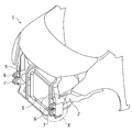
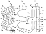
- FIG. 1 is a perspective view showing a vehicle front portion to which an absorber structure according to an embodiment of the present invention is applied. It is a perspective view which shows the state which removed the front bumper in the vehicle front part of FIG. 1, and attached the absorber to the front end surface of a side member. It is an expansion perspective view of the X section in FIG. BRIEF DESCRIPTION OF THE DRAWINGS The absorber of the structure which concerns on embodiment of this invention is shown, (a) is the perspective view, (b) is the side view, (c) is the front view.
- FIG. 1 shows a state where a load is applied from the front of a vehicle to an absorber having a structure according to an embodiment of the present invention
- (a) is a side view of the absorber before a load is input (before a collision)
- (b) is a side view. It is a side view of the absorber after load input (after a collision).
- FIG. 1 to 6 show the absorber structure of the front portion of the vehicle according to the embodiment of the present invention.
- the vehicle front portion 1 to which the absorber structure according to the embodiment of the present invention is applied mainly extends along the vehicle front-rear direction and on both the left and right sides in the vehicle width direction.
- a pair of left and right side members 2 arranged at an interval, and a resin bumper net 3 and a front bumper 4 positioned in front of the vehicle of these side members 2 are provided.
- a bumper member is not provided in front of the side member 2 in the vehicle front portion 1 of the present embodiment.
- the bumper net 3 is provided on the rear side of the front bumper 4 and has a function of receiving a relatively small load from the front of the vehicle.
- the side member 2 of the present embodiment is a rigid member that constitutes the main skeleton of the vehicle front portion 1.
- a front end surface 5 having a planar shape extending in the vertical direction is provided on the vehicle front side of each side member 2, and the front end surface 5 is a rod-shaped object (load generating source) For example, it is formed in a vertically long shape along the pedestrian's leg).
- a plurality of (two in this embodiment) absorbers 6 and 7, which are load absorbing materials made of sheet metal, are spot welded W or the like on the front end surfaces 5 of these side members 2. Each is installed.
- the absorbers 6 and 7 are formed in the same shape and size, and are arranged in two stages at the upper and lower portions of the front end surface 5 of the side member 2.
- the same shape means having the same load and deformation characteristics.
- the upper and lower absorbers 6, 7 of the present embodiment are curved circles in which upper portions 6 a, 7 a located in the front of the vehicle protrude toward the front of the vehicle when viewed from the side of the vehicle (side view). Each is formed in an arc-shaped semi-circle.
- the upper and lower absorbers 6 and 7 have a tapered shape in which the middle portions 6b and 7b in the vehicle front-rear direction incline in a tangential direction from the rear ends of the arcuate upper portions 6a and 7a toward the vehicle rearward and extend linearly. Each is formed in a lateral C shape when viewed from the side of the vehicle.
- bottom absorbers 6c, 7c located at the rear of the vehicle are bent at substantially right angles from the rear ends of the intermediate portions 6b, 7b in the vertical direction so that the front ends of the side members 2 are seen from the side of the vehicle. They are formed on the upper and lower surfaces that are joined to overlap the surface 5.
- the upper and lower absorbers 6 and 7 have arch-shaped tip portions, the vertical width on the front side of the vehicle is set to be narrower than the vertical width on the rear side of the vehicle, and are substantially hat-shaped when viewed laterally in the vehicle. Are formed respectively.
- the upper portions 6a and 7a of the tip portions of the upper and lower absorbers 6 and 7 are formed in a semicircular arc shape because the stress concentration points are formed in an arc-shaped upper portion and a C-shaped upper portion as the deformation by the input load proceeds. This is because it moves from the boundary of the intermediate part to the rear flat surface, the buckling occurrence location shifts, and the drop in the load absorption force becomes small.
- the upper and lower absorbers 6 and 7 of this embodiment are integrally formed continuously along the vehicle vertical direction, and one bottom portion 6c and 7c between the adjacent upper and lower absorbers 6 and 7 is one. It is formed in a common and shared shape. That is, the upper and lower absorbers 6 and 7 are configured as one component integrated close to each other, which makes it possible to reduce the number of adjacent bottom portions and the number of spot welding points, thereby reducing the weight of the absorber and mounting work. Man-hours are being reduced.
- the upper and lower absorbers 6 and 7 are formed in a continuous shape that is long in the vertical direction corresponding to the front end face 5 of the side member 2.
- a plurality of (three in the present embodiment) beads 8 extending in the vehicle vertical direction when viewed from the front of the vehicle are formed on the front surfaces of the upper and lower absorbers 6 and 7 of the present embodiment.
- the beads 8 are arranged at a predetermined interval in the vehicle width direction.
- these beads 8 are formed in a shape recessed toward the front end face 5 side of the side member 2, and the depth of the beads 8 of the arc-shaped upper portions 6a, 7a of the upper and lower absorbers 6, 7 is set to the intermediate portion 6b.
- 7b is formed in a size that is recessed deeper than the depth of the bead 8.
- the structure is easy and suitable for protecting the legs of pedestrians.
- the rod-shaped object (for example, a pedestrian's leg) L of FIG. 6 hits from the vehicle front with respect to the vehicle front part 1 provided with the absorber structure which concerns on embodiment of this invention, and the arrow F of FIG.
- the deformation state of the upper and lower absorbers 6 and 7 when the upper and lower absorbers 6 and 7 receive the load of the rod-like object L will be described.
- a load from the front of the vehicle is applied to the tops of the arc-shaped upper portions 6a and 7a of the upper and lower absorbers 6 and 7.
- the said load is applied to the junction of arc-shaped upper part 6a, 7a and intermediate part 6b, 7b by arch-shaped beam rigidity, and it is transmitted to the taper part of intermediate part 6b, 7b.
- the load is dispersed throughout the intermediate portions 6 b and 7 b, so that the fall and distortion of the intermediate portions 6 b and 7 b are suppressed.
- the front ends of the intermediate portions 6b and 7b are deformed in the opening direction, so that the entire intermediate portions 6b and 7b are reduced in angle formed by the bottom portions 6c and 7c and the intermediate portions 6b and 7b. Deform in the direction of
- the intermediate portions 6b and 7b open while increasing the radius of curvature in the vicinity of the junction between the arcuate upper portions 6a and 7a and the intermediate portions 6b and 7b. For this reason, the front ends of the intermediate portions 6b and 7b are taken into the arc-shaped portion to form a new arc, and the straight intermediate portions 6b and 7b are connected so as to be connected to the tangent line.
- the buckling position C gradually moves toward the lower side (the bottoms 6c and 7c side) of the intermediate parts 6b and 7b at the rear of the vehicle.
- the buckling position C moves instead of one, local buckling is eliminated, and uniform load absorption in the time direction can be realized. Accordingly, as shown in FIG. 6 (b), the upper and lower absorbers 6 and 7 are completely crushed by the load from the front of the vehicle of the rod-like object L without causing the lower absorber 7 to be crushed, thereby efficiently absorbing the load. Is possible.
- the initial load absorption involves the rigidity of the top of the arc-shaped upper parts 6a and 7a and the rigidity against the angle change of the base of the intermediate parts 6b and 7b.
- the load absorption involves the rigidity of the arcuate upper portions 6a and 7a and the rigidity of the upper portions of the intermediate portions 6b and 7b, and the latter load absorption involves the rigidity of the intermediate portions 6b and 7b.
- the upper and lower absorbers 6 and 7 made of sheet metal are attached to the front end surface 5 of the side member 2, and each absorber 6 and 7
- the upper portions 6a and 7a, the intermediate portions 6b and 7b, and the bottom portions 6c and 7c, which are sequentially located from the vehicle rear side, are respectively formed in an arc shape when viewed from the side of the vehicle.
- 6b and 7b are formed in a lateral C-shape when viewed from the side of the vehicle extending in a tangential direction from the arcuate top portions 6a and 7a, and the bottom portions 6c and 7c overlap the front end surface 5 of the side member 2 when viewed from the side of the vehicle.
- the upper and lower absorbers 6 and 7 are deformed by the load from the front of the vehicle due to the rod-like object L, the plurality of buckling positions C are gradually formed at the intermediate portions 6b and 7b at the rear of the vehicle. On the bottom 6c, 7c side There is no local buckling becomes possible to selfish move, the upper and lower absorber 6 and 7 would collapse completely. Therefore, in the absorber structure of this embodiment, since the upper and lower absorbers 6 and 7 having constant load and deformation characteristics are provided in the vehicle front portion 1, the load from the front of the vehicle is evenly distributed in the vertical direction. The load can be absorbed evenly and efficiently in the time direction.
- the absorber structure of this embodiment since the three beads 8 extended in the vehicle up-down direction when viewed from the front of the vehicle are formed on the front surfaces of the upper and lower absorbers 6, 7 at intervals in the vehicle width direction, the upper and lower absorbers 6 and 7 plate rigidity can be improved, and the bead 8 can be installed corresponding to the vehicle type without changing the movement of the buckling position of the upper and lower absorbers 6 and 7 due to the load from the front of the vehicle.
- the load absorption amount can be changed by changing the number of installations.
- the bead depth of the arc-shaped upper portions 6a and 7a is formed deeper than the bead depth of the intermediate portions 6b and 7b, thereby deforming the arc-shaped upper portions 6a and 7a. Since it is made smaller than the deformation of 7b, the input load from the front of the vehicle can be controlled, and the buckling point generated in the deformation process of the upper and lower absorbers 6, 7 can be smoothly moved to the intermediate parts 6b, 7b. The load on the legs of the pedestrian can be absorbed efficiently.
- the upper and lower absorbers 6 and 7 are one part continuously formed integrally in the vehicle vertical direction, and the adjacent bottom portions 6c and 7c are shared by one.
- the upper and lower absorbers 6 and 7 can be molded at a time, so that the number of molding processes and joining processes can be reduced, and the cost can be reduced.
- the present invention is not limited to the above-described embodiments, and various modifications and changes can be made based on the technical idea of the present invention.
- the two absorbers 6 and 7 are provided above and below the front end surface 5 of the side member 2, but three or more absorbers are provided along the vehicle vertical direction depending on the applicable vehicle type. It may be done.
Landscapes
- Engineering & Computer Science (AREA)
- Mechanical Engineering (AREA)
- Body Structure For Vehicles (AREA)
- Vibration Dampers (AREA)
Abstract
L'invention porte sur une structure absorbeur pour véhicule. Selon l'invention, dans une section avant de véhicule (1) dans laquelle aucun élément amortisseur tampon n'est présent en avant d'éléments latéraux (2) qui s'étendent vers l'avant et vers l'arrière le long du véhicule, des absorbeurs en tôle (6 et 7) sont attachés aux extrémités avant (5) desdits éléménts latéraux (2), des parties supérieures (6a et 7a) situées aux extrémités avant desdits absorbeurs (6 et 7) sont conformées de manière à former des arcs de cercle, vues du côté du véhicule, des parties médianes (6b et 7b) placées dans les parties centrales des absorbeurs (6 et 7), vues dans la direction avant/arrière du véhicule, sont conformées de manière à s'étendre tangentiellement en partant des parties supérieures en forme d'arc (6a et 7a) et forment des formes ouvertes en V, vues du côté du véhicule, et des parties de base (6c et 7c) placées aux extrémités arrière des absorbeurs (6 et 7) sont formées dans les surfaces supérieures et inférieures réunies en recouvrant les extrémités avant (5) des éléments latéraux (2), vues du côté du véhicule.
Priority Applications (2)
| Application Number | Priority Date | Filing Date | Title |
|---|---|---|---|
| JP2013504610A JP5641129B2 (ja) | 2011-03-16 | 2012-02-03 | 車両前部のアブソーバ構造 |
| CN201280006907.8A CN103338977B (zh) | 2011-03-16 | 2012-02-03 | 车辆前部用吸收体结构 |
Applications Claiming Priority (2)
| Application Number | Priority Date | Filing Date | Title |
|---|---|---|---|
| JP2011-057713 | 2011-03-16 | ||
| JP2011057713 | 2011-03-16 |
Publications (1)
| Publication Number | Publication Date |
|---|---|
| WO2012124402A1 true WO2012124402A1 (fr) | 2012-09-20 |
Family
ID=46830481
Family Applications (1)
| Application Number | Title | Priority Date | Filing Date |
|---|---|---|---|
| PCT/JP2012/052460 Ceased WO2012124402A1 (fr) | 2011-03-16 | 2012-02-03 | Structure absorbeur pour section avant de véhicule |
Country Status (3)
| Country | Link |
|---|---|
| JP (1) | JP5641129B2 (fr) |
| CN (1) | CN103338977B (fr) |
| WO (1) | WO2012124402A1 (fr) |
Cited By (1)
| Publication number | Priority date | Publication date | Assignee | Title |
|---|---|---|---|---|
| CN112703130A (zh) * | 2018-09-12 | 2021-04-23 | 安赛乐米塔尔公司 | 具有钢加强件的保险杠梁 |
Citations (8)
| Publication number | Priority date | Publication date | Assignee | Title |
|---|---|---|---|---|
| DE2149035A1 (de) * | 1971-10-01 | 1973-04-05 | Daimler Benz Ag | Stossfaengeranordnung, insbesondere fuer kraftfahrzeuge |
| JPS62171349U (fr) * | 1986-04-21 | 1987-10-30 | ||
| JPH1044890A (ja) * | 1996-08-06 | 1998-02-17 | Daihatsu Motor Co Ltd | バンパガードの取付構造 |
| JP2001138840A (ja) * | 1999-11-12 | 2001-05-22 | Suzuki Motor Corp | バンパ配設部構造 |
| JP2001158311A (ja) * | 1999-12-02 | 2001-06-12 | Daihatsu Motor Co Ltd | バンパ取付構造 |
| JP2003112587A (ja) * | 2001-07-30 | 2003-04-15 | Aisin Seiki Co Ltd | 車両用バンパ装置及びバンパステー |
| JP2003165401A (ja) * | 2001-11-30 | 2003-06-10 | Suzuki Motor Corp | 車体前部構造 |
| JP2003285704A (ja) * | 2002-02-28 | 2003-10-07 | Honda Motor Co Ltd | 車両用衝撃低減バンパ装置 |
Family Cites Families (5)
| Publication number | Priority date | Publication date | Assignee | Title |
|---|---|---|---|---|
| US5876078A (en) * | 1997-01-21 | 1999-03-02 | Ford Global Technologies, Inc. | Bumper and front rail assembly for vehicle |
| JP2003237507A (ja) * | 2002-02-19 | 2003-08-27 | Om Kogyo Kk | バンパ補強材 |
| GB2394920B (en) * | 2002-11-07 | 2005-09-21 | Ford Global Tech Inc | Motor vehicle having a front end safety device |
| JP4330652B2 (ja) * | 2007-03-28 | 2009-09-16 | ユニプレス株式会社 | 車両用金属製アブソーバ、車両用バンパシステム、自動車バンパ用アブソーバ及び自動車バンパシステム |
| CN201670190U (zh) * | 2010-05-26 | 2010-12-15 | 山东科技大学 | 一种w型汽车保险杠骨架 |
-
2012
- 2012-02-03 CN CN201280006907.8A patent/CN103338977B/zh not_active Expired - Fee Related
- 2012-02-03 WO PCT/JP2012/052460 patent/WO2012124402A1/fr not_active Ceased
- 2012-02-03 JP JP2013504610A patent/JP5641129B2/ja active Active
Patent Citations (8)
| Publication number | Priority date | Publication date | Assignee | Title |
|---|---|---|---|---|
| DE2149035A1 (de) * | 1971-10-01 | 1973-04-05 | Daimler Benz Ag | Stossfaengeranordnung, insbesondere fuer kraftfahrzeuge |
| JPS62171349U (fr) * | 1986-04-21 | 1987-10-30 | ||
| JPH1044890A (ja) * | 1996-08-06 | 1998-02-17 | Daihatsu Motor Co Ltd | バンパガードの取付構造 |
| JP2001138840A (ja) * | 1999-11-12 | 2001-05-22 | Suzuki Motor Corp | バンパ配設部構造 |
| JP2001158311A (ja) * | 1999-12-02 | 2001-06-12 | Daihatsu Motor Co Ltd | バンパ取付構造 |
| JP2003112587A (ja) * | 2001-07-30 | 2003-04-15 | Aisin Seiki Co Ltd | 車両用バンパ装置及びバンパステー |
| JP2003165401A (ja) * | 2001-11-30 | 2003-06-10 | Suzuki Motor Corp | 車体前部構造 |
| JP2003285704A (ja) * | 2002-02-28 | 2003-10-07 | Honda Motor Co Ltd | 車両用衝撃低減バンパ装置 |
Cited By (3)
| Publication number | Priority date | Publication date | Assignee | Title |
|---|---|---|---|---|
| CN112703130A (zh) * | 2018-09-12 | 2021-04-23 | 安赛乐米塔尔公司 | 具有钢加强件的保险杠梁 |
| CN112703130B (zh) * | 2018-09-12 | 2023-10-13 | 安赛乐米塔尔公司 | 具有钢加强件的保险杠梁 |
| US12054112B2 (en) | 2018-09-12 | 2024-08-06 | Arcelormittal | Bumper beam having steel reinforcement |
Also Published As
| Publication number | Publication date |
|---|---|
| JPWO2012124402A1 (ja) | 2014-07-17 |
| CN103338977A (zh) | 2013-10-02 |
| JP5641129B2 (ja) | 2014-12-17 |
| CN103338977B (zh) | 2016-02-03 |
Similar Documents
| Publication | Publication Date | Title |
|---|---|---|
| JP5337123B2 (ja) | 車体前部構造 | |
| CA2876053C (fr) | Structure de partie de support d'aile | |
| US8348033B2 (en) | Impact-absorbing member | |
| JP2008265738A (ja) | 車両用金属製アブソーバ、車両用バンパシステム、自動車バンパ用アブソーバ及び自動車バンパシステム | |
| JPWO2019035185A1 (ja) | バンパービーム及び車両 | |
| CN107107849B (zh) | 车身前部构造 | |
| JP2016533939A (ja) | 車両用緩衝装置システム | |
| JP5671612B2 (ja) | バンパー構造 | |
| JP2017039371A (ja) | 車体前部構造 | |
| JP5237241B2 (ja) | 自動車のバンパー構造体 | |
| JP5641129B2 (ja) | 車両前部のアブソーバ構造 | |
| JP7144529B2 (ja) | バンパのクラッシュボックス | |
| CN104249760A (zh) | 一种汽车前纵梁结构及制造方法 | |
| JP6294128B2 (ja) | バンパ取付け構造 | |
| KR101526420B1 (ko) | 불연속 다중 오버랩 차체 멤버 | |
| JP2012206561A (ja) | バンパステー | |
| JP4845777B2 (ja) | 車両用車枠の衝撃吸収構造 | |
| KR101547279B1 (ko) | 차량용 범퍼빔 유닛 | |
| JP2015189406A (ja) | 車両のバンパ装置 | |
| JP2014136545A (ja) | サスペンションメンバ及びこれを備えた車両前部構造 | |
| JP2017052341A (ja) | 車両前部構造 | |
| JP2018062213A (ja) | ステアリング装置 | |
| CN107953847B (zh) | 吸能盒 | |
| JP2016078563A (ja) | 車両前部構造 | |
| JP2013241160A (ja) | 衝撃吸収式ステアリングコラムの支持装置 |
Legal Events
| Date | Code | Title | Description |
|---|---|---|---|
| 121 | Ep: the epo has been informed by wipo that ep was designated in this application |
Ref document number: 12757784 Country of ref document: EP Kind code of ref document: A1 |
|
| ENP | Entry into the national phase |
Ref document number: 2013504610 Country of ref document: JP Kind code of ref document: A |
|
| NENP | Non-entry into the national phase |
Ref country code: DE |
|
| 122 | Ep: pct application non-entry in european phase |
Ref document number: 12757784 Country of ref document: EP Kind code of ref document: A1 |