WO2012124478A1 - バッテリ温度制御装置 - Google Patents
バッテリ温度制御装置 Download PDFInfo
- Publication number
- WO2012124478A1 WO2012124478A1 PCT/JP2012/055056 JP2012055056W WO2012124478A1 WO 2012124478 A1 WO2012124478 A1 WO 2012124478A1 JP 2012055056 W JP2012055056 W JP 2012055056W WO 2012124478 A1 WO2012124478 A1 WO 2012124478A1
- Authority
- WO
- WIPO (PCT)
- Prior art keywords
- temperature
- battery
- time
- temperature sensor
- heater
- Prior art date
- Legal status (The legal status is an assumption and is not a legal conclusion. Google has not performed a legal analysis and makes no representation as to the accuracy of the status listed.)
- Ceased
Links
Images



Classifications
-
- H—ELECTRICITY
- H01—ELECTRIC ELEMENTS
- H01M—PROCESSES OR MEANS, e.g. BATTERIES, FOR THE DIRECT CONVERSION OF CHEMICAL ENERGY INTO ELECTRICAL ENERGY
- H01M10/00—Secondary cells; Manufacture thereof
- H01M10/60—Heating or cooling; Temperature control
- H01M10/62—Heating or cooling; Temperature control specially adapted for specific applications
- H01M10/625—Vehicles
-
- H—ELECTRICITY
- H01—ELECTRIC ELEMENTS
- H01M—PROCESSES OR MEANS, e.g. BATTERIES, FOR THE DIRECT CONVERSION OF CHEMICAL ENERGY INTO ELECTRICAL ENERGY
- H01M10/00—Secondary cells; Manufacture thereof
- H01M10/60—Heating or cooling; Temperature control
- H01M10/63—Control systems
- H01M10/633—Control systems characterised by algorithms, flow charts, software details or the like
-
- H—ELECTRICITY
- H01—ELECTRIC ELEMENTS
- H01M—PROCESSES OR MEANS, e.g. BATTERIES, FOR THE DIRECT CONVERSION OF CHEMICAL ENERGY INTO ELECTRICAL ENERGY
- H01M10/00—Secondary cells; Manufacture thereof
- H01M10/42—Methods or arrangements for servicing or maintenance of secondary cells or secondary half-cells
- H01M10/48—Accumulators combined with arrangements for measuring, testing or indicating the condition of cells, e.g. the level or density of the electrolyte
- H01M10/486—Accumulators combined with arrangements for measuring, testing or indicating the condition of cells, e.g. the level or density of the electrolyte for measuring temperature
-
- H—ELECTRICITY
- H01—ELECTRIC ELEMENTS
- H01M—PROCESSES OR MEANS, e.g. BATTERIES, FOR THE DIRECT CONVERSION OF CHEMICAL ENERGY INTO ELECTRICAL ENERGY
- H01M10/00—Secondary cells; Manufacture thereof
- H01M10/60—Heating or cooling; Temperature control
- H01M10/61—Types of temperature control
- H01M10/615—Heating or keeping warm
-
- H—ELECTRICITY
- H01—ELECTRIC ELEMENTS
- H01M—PROCESSES OR MEANS, e.g. BATTERIES, FOR THE DIRECT CONVERSION OF CHEMICAL ENERGY INTO ELECTRICAL ENERGY
- H01M10/00—Secondary cells; Manufacture thereof
- H01M10/60—Heating or cooling; Temperature control
- H01M10/63—Control systems
- H01M10/635—Control systems based on ambient temperature
-
- H—ELECTRICITY
- H01—ELECTRIC ELEMENTS
- H01M—PROCESSES OR MEANS, e.g. BATTERIES, FOR THE DIRECT CONVERSION OF CHEMICAL ENERGY INTO ELECTRICAL ENERGY
- H01M50/00—Constructional details or processes of manufacture of the non-active parts of electrochemical cells other than fuel cells, e.g. hybrid cells
- H01M50/20—Mountings; Secondary casings or frames; Racks, modules or packs; Suspension devices; Shock absorbers; Transport or carrying devices; Holders
- H01M50/204—Racks, modules or packs for multiple batteries or multiple cells
-
- H—ELECTRICITY
- H02—GENERATION; CONVERSION OR DISTRIBUTION OF ELECTRIC POWER
- H02J—ELECTRIC POWER NETWORKS; CIRCUIT ARRANGEMENTS OR SYSTEMS FOR SUPPLYING OR DISTRIBUTING ELECTRIC POWER; SYSTEMS FOR STORING ELECTRIC ENERGY
- H02J7/00—Circuit arrangements for charging or discharging batteries or for supplying loads from batteries
- H02J7/50—Circuit arrangements for charging or discharging batteries or for supplying loads from batteries acting upon multiple batteries simultaneously or sequentially
-
- H—ELECTRICITY
- H02—GENERATION; CONVERSION OR DISTRIBUTION OF ELECTRIC POWER
- H02J—ELECTRIC POWER NETWORKS; CIRCUIT ARRANGEMENTS OR SYSTEMS FOR SUPPLYING OR DISTRIBUTING ELECTRIC POWER; SYSTEMS FOR STORING ELECTRIC ENERGY
- H02J7/00—Circuit arrangements for charging or discharging batteries or for supplying loads from batteries
- H02J7/60—Circuit arrangements for charging or discharging batteries or for supplying loads from batteries including safety or protection arrangements
-
- H—ELECTRICITY
- H02—GENERATION; CONVERSION OR DISTRIBUTION OF ELECTRIC POWER
- H02J—ELECTRIC POWER NETWORKS; CIRCUIT ARRANGEMENTS OR SYSTEMS FOR SUPPLYING OR DISTRIBUTING ELECTRIC POWER; SYSTEMS FOR STORING ELECTRIC ENERGY
- H02J7/00—Circuit arrangements for charging or discharging batteries or for supplying loads from batteries
- H02J7/80—Circuit arrangements for charging or discharging batteries or for supplying loads from batteries including monitoring or indicating arrangements
-
- H—ELECTRICITY
- H01—ELECTRIC ELEMENTS
- H01M—PROCESSES OR MEANS, e.g. BATTERIES, FOR THE DIRECT CONVERSION OF CHEMICAL ENERGY INTO ELECTRICAL ENERGY
- H01M10/00—Secondary cells; Manufacture thereof
- H01M10/60—Heating or cooling; Temperature control
- H01M10/65—Means for temperature control structurally associated with the cells
- H01M10/657—Means for temperature control structurally associated with the cells by electric or electromagnetic means
- H01M10/6571—Resistive heaters
-
- H—ELECTRICITY
- H01—ELECTRIC ELEMENTS
- H01M—PROCESSES OR MEANS, e.g. BATTERIES, FOR THE DIRECT CONVERSION OF CHEMICAL ENERGY INTO ELECTRICAL ENERGY
- H01M2220/00—Batteries for particular applications
- H01M2220/20—Batteries in motive systems, e.g. vehicle, ship, plane
-
- Y—GENERAL TAGGING OF NEW TECHNOLOGICAL DEVELOPMENTS; GENERAL TAGGING OF CROSS-SECTIONAL TECHNOLOGIES SPANNING OVER SEVERAL SECTIONS OF THE IPC; TECHNICAL SUBJECTS COVERED BY FORMER USPC CROSS-REFERENCE ART COLLECTIONS [XRACs] AND DIGESTS
- Y02—TECHNOLOGIES OR APPLICATIONS FOR MITIGATION OR ADAPTATION AGAINST CLIMATE CHANGE
- Y02E—REDUCTION OF GREENHOUSE GAS [GHG] EMISSIONS, RELATED TO ENERGY GENERATION, TRANSMISSION OR DISTRIBUTION
- Y02E60/00—Enabling technologies; Technologies with a potential or indirect contribution to GHG emissions mitigation
- Y02E60/10—Energy storage using batteries
-
- Y—GENERAL TAGGING OF NEW TECHNOLOGICAL DEVELOPMENTS; GENERAL TAGGING OF CROSS-SECTIONAL TECHNOLOGIES SPANNING OVER SEVERAL SECTIONS OF THE IPC; TECHNICAL SUBJECTS COVERED BY FORMER USPC CROSS-REFERENCE ART COLLECTIONS [XRACs] AND DIGESTS
- Y02—TECHNOLOGIES OR APPLICATIONS FOR MITIGATION OR ADAPTATION AGAINST CLIMATE CHANGE
- Y02T—CLIMATE CHANGE MITIGATION TECHNOLOGIES RELATED TO TRANSPORTATION
- Y02T10/00—Road transport of goods or passengers
- Y02T10/60—Other road transportation technologies with climate change mitigation effect
- Y02T10/70—Energy storage systems for electromobility, e.g. batteries
Definitions
- the present invention relates to a battery temperature control device for preventing a temperature drop of a battery used in a cold region, particularly when not in use.
- the battery electrolyte may freeze when not in use.
- the state of charge SOC does not decrease, but the input / output power to the battery decreases due to the increase in internal resistance.
- the battery electrolyte freezes the input / output power of the battery finally reaches zero.
- the vehicle cannot run.
- the battery temperature control device is for adjusting the temperature of the on-vehicle battery, and when the outside air temperature is lower than the minimum temperature when the ignition switch is turned off, the battery is heated by a heater.
- the battery is heated by the heater only according to the outside air temperature when the ignition switch is OFF, Although the outside air temperature when the ignition switch is OFF is high and the heater is not turned ON when the ignition switch is OFF, the heater will continue to be turned OFF even when the outside air temperature subsequently decreases.
- the restart time based on temperature information from the failed temperature sensor is changed to the time for temperature sensor failure, so that the restart time is extremely long as ⁇ .
- the battery temperature control apparatus is configured as follows. First, a battery temperature control apparatus which is a premise of the present invention will be described. This is to adjust the temperature of a battery by heating it with a heater when the temperature drops.
- the present invention is characterized in that the battery temperature control device is provided with a heating necessity determination unit and a temperature sensor failure time setting unit as described below.
- the former heating necessity determination means determines whether or not the battery is in the above-described temperature drop state when a set time determined based on temperature information obtained from individual temperature sensors that detect temperatures at a plurality of locations has elapsed. It is determined whether or not heating by the heater is necessary.
- the latter temperature sensor failure time setting means changes the setting time when the temperature sensor fails, the time corresponding to only the temperature information from the normal temperature sensor, or the temperature information from the normal temperature sensor. It is determined at a fixed time when neither is used.
- Whether or not the battery is warmed by the heater when the set time determined based on the temperature information from the temperature sensors that detect the temperature at a plurality of points has elapsed and whether or not the battery is in the above-described temperature drop state is determined again. To determine Initially, even if the heater is not turned on based on the temperature information, it is determined again whether the battery is in the above-mentioned temperature drop state when the above-mentioned predicted time has elapsed (determining whether the heater needs to be heated) Will be performed.
- the heater is not turned ON at the beginning, if the battery subsequently falls in the above-described temperature drop state, the temperature of the battery can be reliably adjusted by heating with the heater. Therefore, it is possible to avoid the battery from being left in the above-mentioned temperature drop state, and it is possible to prevent the battery electrolyte from falling into a worst case such as freezing.
- FIG. 1 is a control system diagram showing an outline of a battery temperature control device according to a first embodiment of the present invention.
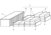
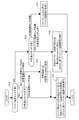
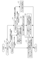
- FIG. 2 is a perspective view of a battery showing the installation procedure of the heater in FIG. 2 is a flowchart showing a battery temperature control program executed by a temperature controller in FIG.
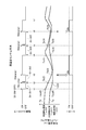
- FIG. 4 is an operation time chart showing the operation by the control program shown in FIG. 3 when both temperature sensors are normal.
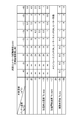
- FIG. 5 is a map diagram of the next controller activation time obtained when the battery temperature during non-use of the battery is in a temperature range where there is no possibility of freezing in FIG.
- FIG. 4 is an operation time chart showing an operation by the control program shown in FIG. 3 when an outside air temperature sensor fails.
- FIG. 4 is an operation time chart showing the operation by the control program shown in FIG. 3 when the battery temperature sensor fails.
- 4 is a flowchart similar to FIG. 3, showing a battery temperature control program of a battery temperature control device according to a second embodiment of the present invention.
- FIG. 1 is a control system diagram of a battery temperature control device according to a first embodiment of the present invention.
- this battery temperature control device is used to adjust the temperature of a high-power battery 1 of an electric vehicle such as an electric vehicle or a hybrid vehicle. To do.
- the high-power battery 1 has a large capacity that can be used for motor driving by integrating a plurality of battery modules 1a, 1b, and 1c in which a plurality of battery shells are stacked into one set.
- the battery module 1a is a battery shell vertically stacked and stacked in the vehicle width direction, located below the vehicle rear seat floor panel
- the battery module 1b is formed by stacking two battery stacks in the vertical direction of the vehicle with the battery shell placed horizontally, and is located below the vehicle rear seat foot floor panel.
- the battery module is a battery module in which the battery shell is placed horizontally and stacked in four steps in the vehicle vertical direction, and is located below the vehicle front seat floor panel.
- 2 is a heater for adjusting the temperature of the battery 1. As shown in FIG. 2, the heater 2 is arranged along the stacking direction of the battery shells with respect to each battery module 1a, 1b, 1c. The battery modules 1a, 1b, 1c are provided in the immediate vicinity.
- reference numeral 3 denotes an electric motor used for driving the electric vehicle.
- the electric motor 3 is electrically connected to the battery 1 via the inverter 4.
- the main relay switch 5 is inserted in the electric circuit between the inverter 4 and the battery 1,
- the main relay switch 5 is opened and closed via a drive controller (not shown) in conjunction with the ignition switch 6 of the electric vehicle, and is closed when the ignition switch 6 is turned on and opened when the ignition switch 6 is turned off.
- the electric vehicle can be driven by driving the motor 3.
- the main relay switch 5 is opened in conjunction with the OFF of the ignition switch 6, the DC power from the battery 1 cannot go to the electric motor 3, and the electric vehicle can be kept stopped by stopping the motor 3. .
- a charger 7 is connected between the DC side of the inverter 4 and the main relay switch 5, and when connecting the charger 7 to an external power source, the main relay switch 5 is closed by a charge controller (not shown), The battery 1 can be charged by an external power source.
- ⁇ Battery temperature control device The temperature control device for the battery 1 provided for the above will be described below.
- the heater 2 provided along the stacking direction of the battery shells in the immediate vicinity of each battery module 1a, 1b, 1c so that the temperature of the battery 1 can be adjusted is as shown in FIG. Electrical connection is made between the DC side and the main relay switch 5, and the heater switch 8 is inserted in the electric path between the connection portion and the heater 2.
- the opening and closing of the heater switch 8 is controlled by a temperature control controller 9 (a battery built-in and self-startable controller) that controls the temperature of the battery 1.
- the temperature controller 9 also opens and closes the main relay switch 5 while the main relay switch 5 is opened in conjunction with the ignition switch 6 being turned off.
- the switch 8 is closed, the main relay switch 5 is also closed in synchronism with this, and the heater 2 is energized (ON), and when the heater switch 8 is opened, the main relay switch 5 is also opened in synchronism with this. 2 shall be defeated (OFF).
- the temperature controller 9 has an ON / OFF control of the heater 2 through the above-described synchronous closing and opening of the heater switch 8 and the main relay switch 5. ON / OFF signal of the ignition switch 6, A signal from the battery temperature sensor 12 for detecting the temperature Tb of the battery 1, A signal from the outside air temperature sensor 13 for detecting the outside air temperature Ta is input.
- the temperature controller 9 executes the control program shown in FIG. 3 when the ignition switch 6 is OFF, and performs temperature control of the battery 1 in the following manner.
- step S11 it is checked whether or not the battery temperature sensor 12 is normal.
- steps S12 and S13 it is checked whether or not the outside air temperature sensor 13 is normal. In making these determinations, if the detected values of the battery temperature sensor 12 and the outside air temperature sensor 13 exceed the abnormality determination value and are large or small, it is determined that the corresponding temperature sensor has failed, and the battery temperature sensor 12 When the detected value of the outside air temperature sensor 13 is within a predetermined range, it is determined that the corresponding temperature sensor is normal.
- the battery 1 is composed of a large number of battery modules 1a, 1b, and 1c as shown in FIG. 2, and thus there are a plurality of battery temperature sensors 12. In this case, all battery temperatures are It is determined that the battery temperature sensor 12 has failed when the sensor 12 has failed. If at least one normal battery temperature sensor 12 exists, the temperature information from the normal battery temperature sensor 12 and the temperature information from the normal outside air temperature sensor 13 will be described below. It is assumed that battery temperature control is performed when the temperature sensor is normal.
- step S11 When it is determined in step S11 that the battery temperature sensor 12 is normal and it is determined in step S12 that the outside air temperature sensor 13 is normal, that is, when both the temperature sensors 12, 13 are normal, the control is performed in step S14.
- the battery temperature control when the temperature sensor is normal is performed as described below with reference to FIGS.
- FIG. 4 is an operation time chart when the outside air temperature Ta and the battery temperature Tb change with time as shown in the figure.
- the main time is linked with the ON of the ignition switch 6.
- the relay switch 5 is closed and the vehicle can be driven by driving the electric motor 3, and no battery temperature control is performed in this embodiment.
- This warming start temperature Tb_start is a set value for determining whether or not the electrolyte of the battery 1 may freeze and needs to be warmed by the heater 2, and is determined as follows, for example.
- the battery electrolyte freezes when the battery temperature Tb becomes lower than the electrolyte solution freezing point temperature Tb_low (for example, about -25 ° C. to ⁇ 30 ° C.), and the input / output power of the battery 1 becomes zero.
- the battery 1 is removed by the heater 2 when the battery temperature Tb becomes low, for example, about ⁇ 20 ° C., more preferably about ⁇ 17 ° C. It is better to warm.
- a temperature of about ⁇ 17 ° C. is set as the heating start temperature Tb_start.
- a temperature of about ⁇ 10 ° C. is set as the heating stop temperature Tb_stop at which the heating by the heater 2 is to be stopped.
- the temperature controller 9 closes the heater switch 8 and the main relay switch 5 to As shown in FIG. 4, the heater 2 is operated (ON) by the electric power from the battery 1, and the battery 1 is heated by the heater 2. With this heating, the battery temperature Tb gradually rises as shown in the figure, and at the instant t4 when the battery temperature Tb rises to the heating stop temperature Tb_stop, the temperature controller 9 opens the heater switch 8 and the main relay switch 5 Then, as shown in the figure, the heater 2 is turned off to end the heating of the battery 1.
- a time ⁇ t4 until 4) decreases to the heating start temperature Tb_start is predicted, and this time ⁇ t4 is set as a sleep time (next controller activation time) ⁇ t until the next temperature controller 9 is activated.
- the time ⁇ t5 is set to a sleep time (next controller activation time) ⁇ t until the next temperature control controller 9 is activated.
- the temperature controller 9 closes the heater switch 8 and the main relay switch 5 to As shown in FIG. 4, the heater 2 is operated (ON) by the electric power from the battery 1, and the battery 1 is heated by the heater 2. Due to this heating, the battery temperature Tb gradually increases as shown in the figure, and at the instant t7 when the battery temperature Tb rises to the heating stop temperature Tb_stop, the temperature controller 9 opens the heater switch 8 and the main relay switch 5 Then, as shown in the figure, the heater 2 is turned off to end the heating of the battery 1.
- Step S14 in FIG. 3 corresponds to the heating necessity determination means in the present invention since the above control is performed.
- the battery temperature Tb starts to be heated again by the above wakeup when the next controller activation time ⁇ t elapses. It is determined whether or not the temperature has fallen below Tb_start (determining whether heating by the heater 2 is necessary). For this reason, even if the heater 2 is not operated at first because Tb ⁇ Tb_start, the temperature of the battery 1 can be reliably adjusted by the heating by the heater 2 when Tb ⁇ Tb_start due to the subsequent temperature drop. Therefore, it can be avoided that the battery 1 is kept below the heating start temperature Tb_start, and the worst situation in which the battery electrolyte freezes can be prevented.
- the above effect can be obtained by heating the battery 1 with the heater 2 only when it is determined that Tb ⁇ Tb_start due to the wake-up of the temperature controller 9 the next time the controller activation time ⁇ t elapses. So that When the battery 1 is not in use due to the ignition switch 6 being turned off, the heater 2 operates only when it is really necessary (when Tb ⁇ Tb_start is judged), and the above effect can be achieved with minimal power consumption. Thus, the state of charge of the battery 1 can be maintained at a level at which the vehicle can travel for a long time.
- step S11 of FIG. 3 it is determined in step S11 of FIG. 3 that the battery temperature sensor 12 is normal, when it is determined in step S12 that the outside temperature sensor 13 is abnormal, that is, the battery temperature sensor 12 is normal, the outside temperature sensor 13 is normal. In the case where is malfunctioning, the control proceeds to step S15, and the temperature information from the malfunctioning outside air temperature sensor 13 is not used, and the outside temperature Ta is set to a fixed value Ta_const.
- step S14 The battery temperature control performed in step S14 in this case will be described below with reference to FIG.
- the outside air temperature Ta and the battery temperature Tb each changed with time as shown in the figure at first, but the outside air temperature sensor 13 broke down at the instant t0 before the instant t1 when the ignition switch 6 was turned off.
- the temperature information from the malfunctioning outside air temperature sensor 13 is not used, and the outside air temperature Ta is set to a fixed value Ta_const (step S15).
- Ta Ta_const between the instants t0 and t1 does not participate in the battery temperature control.
- Time ⁇ t1 is predicted, and this time ⁇ t1 is set as a sleep time (next controller activation time) ⁇ t until the next temperature controller 9 is activated.
- the time ⁇ t3 is predicted, and this time ⁇ t3 is set to a sleep time (next controller activation time) ⁇ t until the next temperature controller 9 is activated.
- the temperature controller 9 closes the heater switch 8 and the main relay switch 5 to As shown in FIG. 6, the heater 2 is operated (ON) by the electric power from the battery 1, and the battery 1 is heated by the heater 2. Due to this heating, the battery temperature Tb gradually rises as shown in the figure, and at the instant t5 when the battery temperature Tb rises to the heating stop temperature Tb_stop, the temperature controller 9 opens the heater switch 8 and the main relay switch 5. Then, as shown in the figure, the heater 2 is turned off to end the heating of the battery 1.
- a sleep state is entered with the heater 2 turned off.
- the time ⁇ t8 is predicted, and this time ⁇ t8 is set as a sleep time (next controller activation time) ⁇ t until the next temperature controller 9 is activated.
- the temperature controller 9 closes the heater switch 8 and the main relay switch 5 to As shown in FIG. 6, the heater 2 is operated (ON) by the electric power from the battery 1, and the battery 1 is heated by the heater 2. With this heating, the battery temperature Tb gradually rises as shown in the figure, and at the instant t10 when the battery temperature Tb rises to the heating stop temperature Tb_stop, the temperature controller 9 opens the heater switch 8 and the main relay switch 5 Then, as shown in the figure, the heater 2 is turned off to end the heating of the battery 1.
- Step S14 in FIG. 3 corresponds to the heating necessity determination means and the temperature sensor failure set time changing means in the present invention because the above control is performed.
- the temperature information from the malfunctioning outside air temperature sensor 13 does not cause the next controller activation time ⁇ t to become extremely long as ⁇ , and the battery temperature Tb to be re-executed when the next controller activation time ⁇ t elapses is added. Whether the temperature is lower than the temperature start temperature Tb_start (determining whether heating by the heater 2 is necessary) is reliably performed even when the outside air temperature sensor 13 fails, and heating becomes impossible and the battery 1 is frozen. Can be avoided.
- step S11 of FIG. 3 When it is determined in step S11 of FIG. 3 that the battery temperature sensor 12 has failed and it is determined in step S13 that the outside air temperature sensor 13 is normal, that is, the outside temperature sensor 13 is normal, but the battery temperature sensor 12 , The control proceeds to step S16, and the temperature information from the failed battery temperature sensor 12 is naturally not used, and the temperature information from the normal outside air temperature sensor 13 is not used.
- the next controller activation time ⁇ t is set to a fixed value ⁇ t_const without depending on the map search of FIG. 5, and the battery temperature control is performed based on this.
- FIG. 7 shows that the outside temperature Ta and the battery temperature Tb change with time as shown in the figure, but the battery temperature sensor 12 has failed at the instant t0 before the instant t1 when the ignition switch 6 is turned off.
- the temperature information from the battery temperature sensor 12 is not used, and the temperature information from the normal outside air temperature sensor 13 is not used, and the next controller activation time ⁇ t is set to a fixed value ⁇ t_const. is there.
- the main relay switch 5 is closed in conjunction with the ignition switch 6 being turned on, and the vehicle can be driven by the drive of the electric motor 3. Do not perform any battery temperature control.
- Step S16 in FIG. 3 corresponds to the temperature sensor failure set time changing means and the heating necessity determination means in the present invention because the above control is performed.
- the temperature controller 9 closes the heater switch 8 and the main relay switch 5 to As shown in FIG. 7, the heater 2 is operated (ON) by the electric power from the battery 1, and the battery 1 is heated by the heater 2.
- the temperature controller 9 opens the heater switch 8 and the main relay switch 5 Then, as shown in the figure, the heater 2 is turned off to end the heating of the battery 1.
- the time ⁇ t7 is set as a sleep time (next controller activation time) ⁇ t until the next temperature controller 9 is activated.
- the temperature controller 9 closes the heater switch 8 and the main relay switch 5 to As shown in FIG. 7, the heater 2 is operated (ON) by the electric power from the battery 1, and the battery 1 is heated by the heater 2. With this heating, the battery temperature Tb gradually rises as shown in the figure, and at the instant t9 when the battery temperature Tb rises to the heating stop temperature Tb_stop, the temperature controller 9 opens the heater switch 8 and the main relay switch 5 Then, as shown in the figure, the heater 2 is turned off to end the heating of the battery 1.
- the next controller activation time ⁇ t that is the sleep time until the temperature controller 9 is activated while the battery 1 is not in use due to the ignition switch 6 being turned off is set to a fixed value ⁇ t_const. None, because every time the next controller activation time ⁇ t elapses, the temperature controller 9 is woken up and the control program shown in FIG. 3 is executed.
- the failure of the battery temperature sensor 12 is corrected and the battery temperature sensor 12 returns to function, the same battery temperature control as when the temperature sensor is normal is performed reliably and promptly at the time of wakeup immediately after the function return.
- the temperature information from the malfunctioning battery temperature sensor 12 does not cause the next controller start time ⁇ t to become extremely long as ⁇ , and the function of the battery temperature sensor 12 is restored when the next controller start time ⁇ t elapses. If Tb ⁇ TTb_start determination of battery temperature Tb (determining whether heating by heater 2 is necessary) is performed reliably, the battery temperature sensor 12 returns to its function but cannot be heated, and the battery 1 The problem of freezing can be avoided.
- step S11 and step S13 in FIG. 3 When it is determined in step S11 and step S13 in FIG. 3 that both the battery temperature sensor 12 and the outside air temperature sensor 13 are out of order, the control proceeds to step S17, and the temperature information from both the temperature sensors 12, 13 is obtained.
- the next controller activation time ⁇ t is set to a fixed value ⁇ t_const without relying on the map search of FIG. 5, and the battery temperature control is performed based on this.
- the fixed next controller activation time ⁇ t ⁇ t_const is shorter than the next controller activation time ⁇ t when both the temperature sensors 12 and 13 are normal, as described above with reference to step S16 in FIG. , 13 should be determined so that the heater 1 is warmed up early by the heater 2 when the function returns.
- step S17 The battery temperature control performed in step S17 is performed in the same manner as described above for step S16.
- the temperature information from the failed battery temperature sensor 12, 13 does not become extremely long as the next controller activation time ⁇ t as ⁇ , and when the next controller activation time ⁇ t has elapsed, the battery temperature sensor 12, If function 13 is restored, battery temperature Tb Tb ⁇ Tb_start judgment (whether heating by heater 2 is necessary) is reliably performed, and the battery temperature sensors 12 and 13 are warmed even after the function is restored. It is possible to avoid the problem that the battery 1 is frozen and the battery 1 is frozen.
- FIG. 8 shows a battery temperature control program of the battery temperature control apparatus according to the second embodiment of the present invention.
- This embodiment basically has the same configuration as that of the first embodiment, and executes the battery temperature control program shown in FIG. 8 instead of the battery temperature control program shown in FIG. 3 of the first embodiment.
- Steps S11 to S14 and Step S17 in FIG. 8 perform the same processing as the steps with the same reference numerals in FIG. 3, so that the description thereof will be omitted and steps S21 to S23 different from those in FIG. I will only explain it.
- step S21 which is determined at the time of failure of the outside air temperature sensor 13, in which it is determined that the battery temperature sensor 12 is normal in step S11, but the outside air temperature sensor 13 is abnormal in step S12,
- this does not use the temperature information from the malfunctioning outside temperature sensor 13, nor does it use the temperature information from the normal battery temperature sensor 12, and does not rely on the map search in FIG. 5 for the next controller startup time ⁇ t.
- a fixed value ⁇ t_const is set, and based on this, the battery temperature control as described above with reference to FIG. 7 is performed.
- step S21 performs the above-described control, it corresponds to a heating necessity determination unit and a temperature sensor failure set time change unit in the present invention.
- Step S22 and Step S23 which are sequentially selected when the battery temperature sensor 12 fails, it is determined in Step S11 that the battery temperature sensor 12 has failed, and it is determined in Step S13 that the outside air temperature sensor 13 is normal.
- the battery temperature control is performed as follows.
- step S22 since the battery temperature sensor 12 has failed, the battery temperature Tb is set to the fixed value Tb_const without using the temperature information from the failed battery temperature sensor 12.
- step S22 and step S23 perform the above-described control, they correspond to a heating necessity determination unit and a temperature sensor failure time setting unit in the present invention.
Landscapes
- Engineering & Computer Science (AREA)
- Chemical & Material Sciences (AREA)
- Chemical Kinetics & Catalysis (AREA)
- Electrochemistry (AREA)
- General Chemical & Material Sciences (AREA)
- Manufacturing & Machinery (AREA)
- Power Engineering (AREA)
- Automation & Control Theory (AREA)
- Secondary Cells (AREA)
- Electric Propulsion And Braking For Vehicles (AREA)
Abstract
Description
バッテリは温度低下すると、蓄電状態SOCが低下するわけではないが、内部抵抗の増大によりバッテリに対する入出力可能電力が低下し、バッテリ電解液が凍結すると、バッテリの入出力可能電力が遂には0になって、バッテリを走行エネルギー源とする電動車両の場合は走行不能に陥る。
このようにバッテリをヒーターで加温して温度調節するバッテリ温度制御装置としては従来、例えば特許文献1に記載のようなものが提案されている。
イグニッションスイッチOFF時の外気温度が高くて、イグニッションスイッチOFF時当初はヒーターをONしなかったものの、その後に外気温度が低下したときも、ヒーターはOFFにされ続けることになる。
これにより温度センサ故障時も確実に、バッテリの温度低下に関する再判定が行われるようになすことで、バッテリが凍結に至るという上記の問題を解消し得るようにしたバッテリ温度制御装置を提案することを目的とする。
先ず本発明の前提となるバッテリ温度制御装置を説明するに、これは、 バッテリを、その温度低下時にヒーターで加温して温度調節するものである。
複数箇所の温度を検出する温度センサからの温度情報に基づいて定めた設定時間の経過時に、バッテリが上記の温度低下状態であるか否かの判定を改めて行い、ヒーターによる加温を行うか否を決定するため、
当初は温度情報に基づきヒーターをONしなかったとしても、上記の予測時間が経過した時に改めて、バッテリが上記の温度低下状態であるか否かの判定(上記ヒーターによる加温の要否判定)を行うこととなる。
従って、バッテリが上記の温度低下状態のままにされるのを回避し得て、例えばバッテリ電解液が凍結するような最悪事態に陥るのを防止することができる。
当該設定時間が∞のごとく極端に長くなることがなく、かかる設定時間の経過時に改めて行うべき、バッテリが上記の温度低下状態であるか否かの判定(上記ヒーターによる加温の要否判定)が、温度センサ故障時も確実に行われることとなり、バッテリが凍結に至るという前記の問題を生ずることがない。
<第1実施例の構成>
図1は、本発明の第1実施例になるバッテリ温度制御装置の制御システム図で、本実施例では、このバッテリ温度制御装置を、電気自動車やハイブリッド車両など電動車両の強電バッテリ1を温度調節するためのものとする。
ここで電池モジュール1aは、電池シェルを縦置きにして車幅方向に積層したもので、車両後席フロアパネルの下方に位置し、
電池モジュール1bは、電池シェルを横置きにして車両上下方向に2段ずつ積層したもので、車両後席足元フロアパネルの下方に位置し、
電池モジュールは、電池シェルを横置きにして車両上下方向に4段ずつ積層したもので、車両前席フロアパネルの下方に位置するものとする。
そして、インバータ4およびバッテリ1間の電路中にメインリレースイッチ5を挿置し、
このメインリレースイッチ5は、電動車両のイグニッションスイッチ6に連動して、図示せざる駆動コントローラを介し開閉され、イグニッションスイッチ6のON時に閉じ、イグニッションスイッチ6のOFF時に開くものとする。
イグニッションスイッチ6のOFFに連動してメインリレースイッチ5が開いている場合、バッテリ1からの直流電力は電動モータ3に向かい得ず、該モータ3の停止により電動車両を停車状態に保つことができる。
上記の用に供されるバッテリ1の温度制御装置を以下に説明する。
図2につき前述した通り、バッテリ1の温度調節を行い得るよう、各電池モジュール1a,1b,1cの直近において電池シェルの積層方向に沿うよう設けたヒーター2は、図1に示すごとくインバータ4の直流側とメインリレースイッチ5との間に電気接続し、この接続部とヒーター2との間の電路中にヒータースイッチ8を挿置する。
この温調コントローラ9は更に、メインリレースイッチ5がイグニッションスイッチ6のOFFに連動して開かれている間、当該メインリレースイッチ5をも開閉するものとし、この際、温調コントローラ9は、ヒータースイッチ8を閉じるとき、これに同期してメインリレースイッチ5をも閉じてヒーター2を附勢(ON)し、ヒータースイッチ8を開くとき、これに同期してメインリレースイッチ5をも開いてヒーター2を滅勢(OFF)するものとする。
前記イグニッションスイッチ6のON,OFF信号と、
バッテリ1の温度Tbを検出するバッテリ温度センサ12からの信号と、
外気温度Taを検出する外気温度センサ13からの信号とを入力する。
ステップS11においては、バッテリ温度センサ12が正常か否かをチェックし、ステップS12およびステップS13においては、外気温度センサ13が正常か否かをチェックする。
これらの判定に当たっては、バッテリ温度センサ12および外気温度センサ13の検出値が異常判定値を超えて大きい場合や、小さい場合に、対応する温度センサが故障していると判定し、バッテリ温度センサ12および外気温度センサ13の検出値が所定範囲の値であるとき、対応する温度センサが正常であると判定する。
そして、正常なバッテリ温度センサ12が1個でも存在していれば、当該正常なバッテリ温度センサ12からの温度情報と、正常な外気温度センサ13からの温度情報とを用いて、以下に説明する温度センサ正常時のバッテリ温度制御を遂行するものとする。
ステップS11においてバッテリ温度センサ12が正常であると判定し、且つステップS12において外気温度センサ13が正常であると判定するとき、つまり両温度センサ12,13が共に正常であるとき、制御をステップS14に進め、図4,5につき以下に説明するごとくに温度センサ正常時のバッテリ温度制御を行う。
バッテリ電解液は、バッテリ温度Tbが電解液凝固点温度Tb_low(例えば-25℃~-30℃程度)よりも低温になるとき凍結し、バッテリ1の入出力可能電力が0になってしまう。
このような最悪事態に絶対陥ることのないようにするには、余裕をみてバッテリ温度Tbが例えば-20℃程度、更に好ましくは-17℃程度の低温になった時からヒーター2によりバッテリ1を加温するのがよい。
従って本実施例では、上記加温開始温度Tb_startとして、例えば-17℃程度の温度を設定する。
本実施例では更に、ヒーター2による加温を停止すべき加温停止温度Tb_stopとして、例えば-10℃程度の温度を設定する。
図5に例示するマップを基に、イグニッションスイッチOFF時t1におけるバッテリ温度Tb=Tb_offおよび外気温度Ta=Ta_offの組み合わせから、バッテリ温度Tb=Tb_offが加温開始温度Tb_startに低下するまでの時間Δt1を予測して、この時間Δt1を、次回温調コントローラ9が起動するまでのスリープ時間(次回コントローラ起動時間)Δtに設定する。
そして温調コントローラ9は内蔵タイマにより、イグニッションスイッチOFF時t1からの経過時間を計測し、次回コントローラ起動時間Δt=Δt1が経過する瞬時t2までの間、ヒータースイッチ8およびメインリレースイッチ5を開くことにより、ヒーター2をOFFにしたスリープ状態となる。
そして温調コントローラ9は内蔵タイマにより、ウエイクアップ時t2からの経過時間を計測し、次回コントローラ起動時間Δt=Δt2が経過する瞬時t3までの間、ヒータースイッチ8およびメインリレースイッチ5を開くことにより、ヒーター2をOFFにしたスリープ状態を維持する。
この加温により、バッテリ温度Tbは図示のごとく徐々に上昇し、バッテリ温度Tbが加温停止温度Tb_stopまで上昇した瞬時t4に、温調コントローラ9はヒータースイッチ8およびメインリレースイッチ5を開くことにより、図示のごとくヒーター2をOFFさせてバッテリ1の加温を終了する。
そして温調コントローラ9は内蔵タイマにより、加温終了瞬時t4からの経過時間を計測し、次回コントローラ起動時間Δt=Δt4が経過する瞬時t5までの間、ヒータースイッチ8およびメインリレースイッチ5を開くことにより、ヒーター2をOFFにしたスリープ状態となる。
そして温調コントローラ9は内蔵タイマにより、ウエイクアップ時t5からの経過時間を計測し、次回コントローラ起動時間Δt=Δt5が経過する瞬時t6までの間、ヒータースイッチ8およびメインリレースイッチ5を開くことにより、ヒーター2をOFFにしたスリープ状態を維持する。
この加温により、バッテリ温度Tbは図示のごとく徐々に上昇し、バッテリ温度Tbが加温停止温度Tb_stopまで上昇した瞬時t7に、温調コントローラ9はヒータースイッチ8およびメインリレースイッチ5を開くことにより、図示のごとくヒーター2をOFFさせてバッテリ1の加温を終了する。
上記した制御の繰り返しにより、イグニッションスイッチ6のOFFによるバッテリ1の不使用中、バッテリ温度Tbが加温開始温度Tb_start以上である間、つまりバッテリ電解液が凍結する虞のない間に、バッテリ温度Tbおよび外気温度Taの組み合わせから、バッテリ温度Tbが加温開始温度Tb_start未満になるであろう時間を予測して、これを次回コントローラ起動時間Δtと定め、
この次回コントローラ起動時間Δtが経過した時、温調コントローラ9の自己起動(ウエイクアップ)により、バッテリ温度Tbが加温開始温度Tb_start未満に低下したか否かの判定を行い、このバッテリ温度低下(Tb<Tb_start )時にヒーター2をバッテリ駆動してバッテリ1の加温を行う。
このため、当初はTb≧Tb_startのためヒーター2を作動させなかったとしても、その後の温度低下によりTb<Tb_startになったら、ヒーター2による加温によってバッテリ1を確実に温度調節することができる。
従って、バッテリ1が加温開始温度Tb_start未満のままにされるのを回避し得て、バッテリ電解液が凍結するような最悪事態となるのを防止することができる。
イグニッションスイッチ6のOFFによるバッテリ1の不使用中は、本当に必要な時(Tb<Tb_startの判定時)にしかヒーター2が作動せず、最小限の消費電力で上記の効果を達成することができ、バッテリ1の蓄電状態を長時間、車両の走行が可能なレベルに保つことができる。
図3のステップS11においてバッテリ温度センサ12が正常であると判定したが、ステップS12で外気温度センサ13が異常であると判定するとき、つまりバッテリ温度センサ12は正常であるものの、外気温度センサ13が故障している場合は、制御をステップS15に進めて、故障している外気温度センサ13からの温度情報を用いず、外気温度Taを固定値Ta_constに設定する。
図6は、外気温度Taおよびバッテリ温度Tbがそれぞれ、当初は図示のごとくに経時変化していたが、イグニッションスイッチ6がOFFされる瞬時t1より前の瞬時t0に外気温度センサ13が故障し、このとき、故障している外気温度センサ13からの温度情報を用いず、外気温度Taを固定値Ta_constに設定した(ステップS15)場合における動作タイムチャートである。
従って、瞬時t0~t1間におけるTa=Ta_constがバッテリ温度制御に関与することはない。
図5に例示するマップを基に、イグニッションスイッチOFF時t1におけるバッテリ温度Tb=Tb_offおよび外気温度Ta_off(固定の外気温度Ta_const)の組み合わせから、バッテリ温度Tb=Tb_offが加温開始温度Tb_startに低下するまでの時間Δt1を予測して、この時間Δt1を、次回温調コントローラ9が起動するまでのスリープ時間(次回コントローラ起動時間)Δtに設定する。
そして温調コントローラ9は内蔵タイマにより、ウエイクアップ時t2からの経過時間を計測し、次回コントローラ起動時間Δt=Δt2が経過する瞬時t3までの間、ヒータースイッチ8およびメインリレースイッチ5を開くことにより、ヒーター2をOFFにしたスリープ状態を維持する。
そして温調コントローラ9は内蔵タイマにより、ウエイクアップ時t3からの経過時間を計測し、次回コントローラ起動時間Δt=Δt3が経過する瞬時t4までの間、ヒータースイッチ8およびメインリレースイッチ5を開くことにより、ヒーター2をOFFにしたスリープ状態を維持する。
この加温により、バッテリ温度Tbは図示のごとく徐々に上昇し、バッテリ温度Tbが加温停止温度Tb_stopまで上昇した瞬時t5に、温調コントローラ9はヒータースイッチ8およびメインリレースイッチ5を開くことにより、図示のごとくヒーター2をOFFさせてバッテリ1の加温を終了する。
そして温調コントローラ9は内蔵タイマにより、加温終了瞬時t5からの経過時間を計測し、次回コントローラ起動時間Δt=Δt5が経過する瞬時t6までの間、ヒータースイッチ8およびメインリレースイッチ5を開くことにより、ヒーター2をOFFにしたスリープ状態となる。
そして温調コントローラ9は内蔵タイマにより、ウエイクアップ時t6からの経過時間を計測し、次回コントローラ起動時間Δt=Δt6が経過する瞬時t7までの間、ヒータースイッチ8およびメインリレースイッチ5を開くことにより、ヒーター2をOFFにしたスリープ状態を維持する。
そして温調コントローラ9は内蔵タイマにより、ウエイクアップ時t7からの経過時間を計測し、次回コントローラ起動時間Δt=Δt7が経過する瞬時t8までの間、ヒータースイッチ8およびメインリレースイッチ5を開くことにより、ヒーター2をOFFにしたスリープ状態を維持する。
そして温調コントローラ9は内蔵タイマにより、ウエイクアップ時t8からの経過時間を計測し、次回コントローラ起動時間Δt=Δt8が経過する瞬時t9までの間、ヒータースイッチ8およびメインリレースイッチ5を開くことにより、ヒーター2をOFFにしたスリープ状態を維持する。
この加温により、バッテリ温度Tbは図示のごとく徐々に上昇し、バッテリ温度Tbが加温停止温度Tb_stopまで上昇した瞬時t10に、温調コントローラ9はヒータースイッチ8およびメインリレースイッチ5を開くことにより、図示のごとくヒーター2をOFFさせてバッテリ1の加温を終了する。
加温終了瞬時t10以降も、上記したと同様な制御が繰り返され、イグニッションスイッチ6のOFFによるバッテリ1の不使用中、正常なバッテリ温度センサ12で検出したバッテリ温度Tbと、故障している外気温度センサ13からの温度情報に代わる固定の外気温度Ta={Ta_const}とに応じた次回コントローラ起動時間Δtに基づき、前記した温度センサ正常時と同様なバッテリ温度制御が行われる。
図3のステップS11においてバッテリ温度センサ12が故障していると判定し、ステップS13で外気温度センサ13が正常であると判定するとき、つまり外気温度センサ13は正常であるものの、バッテリ温度センサ12が故障している場合は、制御をステップS16に進めて、故障しているバッテリ温度センサ12からの温度情報は当然これを用いず、また正常な外気温度センサ13からの温度情報も用いず、次回コントローラ起動時間Δtを、図5のマップ検索に頼らないで固定値Δt_constに設定し、これに基づいてバッテリ温度制御を遂行する。
図7は、外気温度Taおよびバッテリ温度Tbがそれぞれ、図示のごとくに経時変化しているものの、イグニッションスイッチ6がOFFされる瞬時t1より前の瞬時t0にバッテリ温度センサ12が故障したため、故障しているバッテリ温度センサ12からの温度情報は当然これを用いず、また正常な外気温度センサ13からの温度情報も用いず、次回コントローラ起動時間Δtを固定値Δt_constに設定した場合における動作タイムチャートである。
そして、このイグニッションスイッチOFF時t1より温調コントローラ9は内蔵タイマにより、この瞬時t1からの経過時間を計測し、固定の次回コントローラ起動時間Δt=Δt_constが経過する瞬時t2までの間、ヒータースイッチ8およびメインリレースイッチ5の「開」によりヒーター2をOFFにしたスリープ状態を保つ。
このとき温調コントローラ9は、ステップS16において、ヒータースイッチ8およびメインリレースイッチ5を開くことにより、ヒーター2をOFFにしたスリープ状態となる。
このウエイクアップ時t2より温調コントローラ9は内蔵タイマにより、この瞬時t2からの経過時間を計測し、固定の次回コントローラ起動時間Δt=Δt_constが経過する瞬時t3までの間、ヒータースイッチ8およびメインリレースイッチ5の「開」によりヒーター2をOFFにしたスリープ状態を保つ。
このとき温調コントローラ9は、ステップS16において、ヒータースイッチ8およびメインリレースイッチ5を開くことにより、ヒーター2をOFFにしたスリープ状態となる。
このウエイクアップ時t3より温調コントローラ9は内蔵タイマにより、この瞬時t3からの経過時間を計測し、固定の次回コントローラ起動時間Δt=Δt_constが経過する瞬時t5までの間、ヒータースイッチ8およびメインリレースイッチ5の「開」によりヒーター2をOFFにしたスリープ状態を保つ。
そして温調コントローラ9は内蔵タイマにより、加温終了瞬時t6からの経過時間を計測し、次回コントローラ起動時間Δt=Δt6が経過する瞬時t7までの間、ヒータースイッチ8およびメインリレースイッチ5を開くことにより、ヒーター2をOFFにしたスリープ状態となる。
そして温調コントローラ9は内蔵タイマにより、ウエイクアップ時t7からの経過時間を計測し、次回コントローラ起動時間Δt=Δt7が経過する瞬時t8までの間、ヒータースイッチ8およびメインリレースイッチ5を開くことにより、ヒーター2をOFFにしたスリープ状態を維持する。
この加温により、バッテリ温度Tbは図示のごとく徐々に上昇し、バッテリ温度Tbが加温停止温度Tb_stopまで上昇した瞬時t9に、温調コントローラ9はヒータースイッチ8およびメインリレースイッチ5を開くことにより、図示のごとくヒーター2をOFFさせてバッテリ1の加温を終了する。
上記したバッテリ温度センサ故障時におけるバッテリ温度制御によれば、イグニッションスイッチ6のOFFによるバッテリ1の不使用中、温調コントローラ9が起動するまでのスリープ時間である次回コントローラ起動時間Δtを固定値Δt_constとなし、この次回コントローラ起動時間Δtが経過する度に温調コントローラ9をウエイクアップして図3の制御プログラムを実行することとしたため、
バッテリ温度センサ12の故障が直って、バッテリ温度センサ12が機能復帰した場合、当該機能復帰直後のウエイクアップ時に、確実に、且つ速やかに、温度センサ正常時と同様なバッテリ温度制御が行われる。
図3のステップS11およびステップS13でバッテリ温度センサ12および外気温度センサ13が共に故障していると判定する場合は、制御をステップS17に進めて、両温度センサ12,13からの温度情報はこれらを用いず、次回コントローラ起動時間Δtを、図5のマップ検索に頼らないで固定値Δt_constに設定し、これに基づきバッテリ温度制御を遂行する。
これにより、故障しているバッテリ温度センサ12,13からの温度情報で次回コントローラ起動時間Δtが∞のごとく極端に長くなることがなく、かかる次回コントローラ起動時間Δtの経過時に、バッテリ温度センサ12,13が機能復帰していれば、バッテリ温度TbのTb< Tb_start判定(ヒーター2による加温の要否判定)が確実に行われることとなり、バッテリ温度センサ12,13が機能復帰したのに加温不能になってバッテリ1が凍結に至るという問題を回避することができる。
図8は、本発明の第2実施例になるバッテリ温度制御装置のバッテリ温度制御プログラムを示す。
本実施例は、基本的に第1実施例と同様な構成とし、第1実施例の図3に示すバッテリ温度制御プログラムに代えて、図8のバッテリ温度制御プログラムを実行するものとする。
故障している外気温度センサ13からの温度情報は当然これを用いず、また正常なバッテリ温度センサ12からの温度情報も用いず、次回コントローラ起動時間Δtを、図5のマップ検索に頼らないで固定値Δt_constに設定し、これに基づき、図7につき前述したようなバッテリ温度制御を遂行する。
なお、かかる固定のバッテリ温度Tb=Tb_constは、次回コントローラ起動時間Δtが温度センサ正常時よりも短く、温調コントローラ9のウエイクアップが頻繁に行われるようにするのが良い。
Claims (8)
- バッテリを、その温度低下時にヒーターで加温して温度調節するバッテリ温度制御装置において、
複数箇所の温度を検出する個々の温度センサから得られた温度情報に基づいて定めた設定時間の経過時に、バッテリが前記温度低下状態であるか否かの判定を行って前記ヒーターによる加温の要否を判定する加温要否判定手段を具え、
前記温度センサの故障時は前記設定時間を、正常な温度センサからの温度情報のみに応じた時間、若しくは、該正常な温度センサからの温度情報をも用いない固定時間に定める温度センサ故障時設定時間変更手段を設けたバッテリ温度制御装置。 - 請求項1に記載のバッテリ温度制御装置において、
前記設定時間は、バッテリが前記温度低下状態になるであろうと予測した時間であるバッテリ温度制御装置。 - 請求項1に記載のバッテリ温度制御装置において、
前記複数箇所の温度を検出する温度センサは、前記バッテリの温度を検出するバッテリ温度センサと、外気温度を検出する外気温度センサとであるバッテリ温度制御装置。 - 請求項3に記載のバッテリ温度制御装置において、
前記温度センサ故障時設定時間変更手段は、前記外気温度センサが故障した場合、外気温度に関する温度情報を固定値にし、該固定の外気温度情報と、前記バッテリ温度センサからの温度情報とに応じ、前記設定時間を定めるものであることを特徴とするバッテリ温度制御装置。 - 請求項4に記載のバッテリ温度制御装置において、
前記外気温度に関する温度情報の固定値は、正常な前記バッテリ温度センサからの温度情報が最悪条件である場合でも、前記設定時間を、バッテリが前記温度低下状態となるような設定時間よりも短い時間となすものであるバッテリ温度制御装置。 - 請求項3に記載のバッテリ温度制御装置において、
前記温度センサ故障時設定時間変更手段は、前記バッテリ温度センサが故障した場合、前記設定時間を固定時間に定めるものであるバッテリ温度制御装置。 - 請求項6に記載のバッテリ温度制御装置において、
前記固定の設定時間は、バッテリが前記温度低下状態になることのないような短い時間であるバッテリ温度制御装置。 - 請求項1~7のいずれか1項に記載のバッテリ温度制御装置において、
前記複数箇所の温度を検出する温度センサが、複数個の温度センサ群から成るものである場合、前記温度センサ故障時設定時間変更手段は、該温度センサ群を成す全ての温度センサが故障した時をもって温度センサが故障したと見なすものであるバッテリ温度制御装置。
Priority Applications (4)
| Application Number | Priority Date | Filing Date | Title |
|---|---|---|---|
| KR1020137005897A KR101609034B1 (ko) | 2011-03-11 | 2012-02-29 | 배터리 온도 제어 장치 |
| CN201280002822.2A CN103098298B (zh) | 2011-03-11 | 2012-02-29 | 电池温度控制装置 |
| EP12758325.0A EP2685550B1 (en) | 2011-03-11 | 2012-02-29 | Battery temperature control device |
| US13/822,084 US9246201B2 (en) | 2011-03-11 | 2012-02-29 | Battery temperature control device |
Applications Claiming Priority (2)
| Application Number | Priority Date | Filing Date | Title |
|---|---|---|---|
| JP2011-054083 | 2011-03-11 | ||
| JP2011054083A JP5720322B2 (ja) | 2011-03-11 | 2011-03-11 | バッテリ温度制御装置 |
Publications (1)
| Publication Number | Publication Date |
|---|---|
| WO2012124478A1 true WO2012124478A1 (ja) | 2012-09-20 |
Family
ID=46830553
Family Applications (1)
| Application Number | Title | Priority Date | Filing Date |
|---|---|---|---|
| PCT/JP2012/055056 Ceased WO2012124478A1 (ja) | 2011-03-11 | 2012-02-29 | バッテリ温度制御装置 |
Country Status (6)
| Country | Link |
|---|---|
| US (1) | US9246201B2 (ja) |
| EP (1) | EP2685550B1 (ja) |
| JP (1) | JP5720322B2 (ja) |
| KR (1) | KR101609034B1 (ja) |
| CN (1) | CN103098298B (ja) |
| WO (1) | WO2012124478A1 (ja) |
Families Citing this family (24)
| Publication number | Priority date | Publication date | Assignee | Title |
|---|---|---|---|---|
| JP5708070B2 (ja) * | 2011-03-11 | 2015-04-30 | 日産自動車株式会社 | バッテリ温度制御装置 |
| JP5668541B2 (ja) * | 2011-03-11 | 2015-02-12 | 日産自動車株式会社 | 車両の充電制御装置 |
| KR20150102778A (ko) | 2013-11-13 | 2015-09-08 | 삼성에스디아이 주식회사 | 배터리 팩, 배터리 팩을 포함하는 장치, 및 배터리 팩의 관리 방법 |
| JP6358425B2 (ja) * | 2014-06-04 | 2018-07-18 | 三菱自動車工業株式会社 | 車載電池の温調装置 |
| KR101628489B1 (ko) | 2014-09-25 | 2016-06-08 | 현대자동차주식회사 | 차량용 고전압 배터리 제어 장치 및 방법 |
| JP6330639B2 (ja) * | 2014-12-01 | 2018-05-30 | トヨタ自動車株式会社 | 蓄電システムおよびその制御方法 |
| JP6332121B2 (ja) * | 2015-04-14 | 2018-05-30 | トヨタ自動車株式会社 | 電池の昇温装置 |
| JP6488974B2 (ja) * | 2015-10-05 | 2019-03-27 | トヨタ自動車株式会社 | バッテリ装置 |
| JP6414038B2 (ja) * | 2015-12-10 | 2018-10-31 | トヨタ自動車株式会社 | バッテリシステム |
| JP6655453B2 (ja) * | 2016-04-04 | 2020-02-26 | 古河電気工業株式会社 | 二次電池状態検出装置および二次電池状態検出方法 |
| KR102053989B1 (ko) | 2016-05-03 | 2019-12-09 | 주식회사 엘지화학 | 에너지 저장 시스템을 위한 온도 제어 장치 및 방법 |
| JP6520848B2 (ja) * | 2016-07-04 | 2019-05-29 | トヨタ自動車株式会社 | 電動車両のバッテリ充電システム |
| KR102046608B1 (ko) * | 2016-08-12 | 2019-11-19 | 주식회사 엘지화학 | 배터리 팩을 위한 온도 모니터링 장치 및 방법 |
| DE102018208994A1 (de) * | 2018-06-07 | 2019-12-12 | Robert Bosch Gmbh | Verfahren zum betriebssicheren Aktivieren von mindestens einem elektronischen Bauteil |
| CN110838609B (zh) * | 2018-08-15 | 2023-04-07 | 上海汽车集团股份有限公司 | 一种动力电池热失控保护方法、装置及系统 |
| US10604028B1 (en) * | 2019-02-15 | 2020-03-31 | Wisk Aero Llc | Desired departure temperature for a battery in a vehicle |
| CN112349987B (zh) * | 2020-10-30 | 2022-09-13 | 湖北亿纬动力有限公司 | 一种电芯的温控系统的启动方法、装置、设备及存储介质 |
| CN112937370B (zh) * | 2021-02-22 | 2024-05-14 | 北京车和家信息技术有限公司 | 一种车辆动力电池保温控制方法及装置 |
| DE102021203100A1 (de) | 2021-03-29 | 2022-09-29 | Robert Bosch Gesellschaft mit beschränkter Haftung | Verfahren zum Temperieren eines elektrochemischen Energiespeichers |
| CN115720690B (zh) * | 2021-06-24 | 2026-01-16 | 深圳引望智能技术有限公司 | 一种电池的加热方法以及加热装置 |
| DE102021209517A1 (de) * | 2021-08-31 | 2023-03-02 | Robert Bosch Gesellschaft mit beschränkter Haftung | Verfahren zum Betreiben einer Schaltvorrichtung, Schaltvorrichtung, elektrischer Energiespeicher und Vorrichtung |
| FR3131565A1 (fr) * | 2022-01-03 | 2023-07-07 | Psa Automobiles Sa | Contrôle de la température interne d’une batterie principale dans un véhicule endormi |
| CN114678630A (zh) * | 2022-03-30 | 2022-06-28 | 重庆金康赛力斯新能源汽车设计院有限公司 | 一种用于动力电池的主动保温系统和方法 |
| CN118213668B (zh) * | 2024-01-02 | 2025-06-27 | 湘潭大学 | 适用低温环境的电动汽车电池包加热装置及其控制方法 |
Citations (6)
| Publication number | Priority date | Publication date | Assignee | Title |
|---|---|---|---|---|
| JPH11178231A (ja) * | 1997-12-09 | 1999-07-02 | Denso Corp | 電気自動車用組み電池の温度管理装置 |
| JP2003203679A (ja) | 2001-12-28 | 2003-07-18 | Sanyo Electric Co Ltd | 自動車用の電源装置 |
| JP2005339980A (ja) * | 2004-05-26 | 2005-12-08 | Sanyo Electric Co Ltd | 車両用の電源装置 |
| JP2007097336A (ja) * | 2005-09-29 | 2007-04-12 | Mazda Motor Corp | 車両用発電機の制御装置 |
| JP2009034366A (ja) * | 2007-08-02 | 2009-02-19 | Seiko Epson Corp | 脈拍計、電子機器、脈拍測定方法、脈拍測定プログラム、および記憶媒体 |
| JP2010088204A (ja) * | 2008-09-30 | 2010-04-15 | Toyota Motor Corp | 二次電池の充電システム及び車両 |
Family Cites Families (6)
| Publication number | Priority date | Publication date | Assignee | Title |
|---|---|---|---|---|
| JPH0475435A (ja) | 1990-07-13 | 1992-03-10 | Toshiba Battery Co Ltd | 二次電池の充電回路 |
| JP4161081B2 (ja) * | 2006-04-12 | 2008-10-08 | 三菱電機株式会社 | 制御装置一体型発電電動機 |
| JP5178094B2 (ja) * | 2007-08-27 | 2013-04-10 | キヤノン株式会社 | バッテリー、制御方法、及びプログラム |
| DE102007049707A1 (de) * | 2007-10-17 | 2009-04-23 | Robert Bosch Gmbh | Verfahren zur Bestimmung der Speichertemperatur eines elektrischen Speichers und entsprechende Vorrichtung |
| JP4518156B2 (ja) * | 2008-01-28 | 2010-08-04 | 株式会社デンソー | 車両システム |
| JP2010200509A (ja) * | 2009-02-25 | 2010-09-09 | Kyocera Corp | 充電装置 |
-
2011
- 2011-03-11 JP JP2011054083A patent/JP5720322B2/ja active Active
-
2012
- 2012-02-29 EP EP12758325.0A patent/EP2685550B1/en active Active
- 2012-02-29 CN CN201280002822.2A patent/CN103098298B/zh active Active
- 2012-02-29 US US13/822,084 patent/US9246201B2/en active Active
- 2012-02-29 KR KR1020137005897A patent/KR101609034B1/ko active Active
- 2012-02-29 WO PCT/JP2012/055056 patent/WO2012124478A1/ja not_active Ceased
Patent Citations (6)
| Publication number | Priority date | Publication date | Assignee | Title |
|---|---|---|---|---|
| JPH11178231A (ja) * | 1997-12-09 | 1999-07-02 | Denso Corp | 電気自動車用組み電池の温度管理装置 |
| JP2003203679A (ja) | 2001-12-28 | 2003-07-18 | Sanyo Electric Co Ltd | 自動車用の電源装置 |
| JP2005339980A (ja) * | 2004-05-26 | 2005-12-08 | Sanyo Electric Co Ltd | 車両用の電源装置 |
| JP2007097336A (ja) * | 2005-09-29 | 2007-04-12 | Mazda Motor Corp | 車両用発電機の制御装置 |
| JP2009034366A (ja) * | 2007-08-02 | 2009-02-19 | Seiko Epson Corp | 脈拍計、電子機器、脈拍測定方法、脈拍測定プログラム、および記憶媒体 |
| JP2010088204A (ja) * | 2008-09-30 | 2010-04-15 | Toyota Motor Corp | 二次電池の充電システム及び車両 |
Non-Patent Citations (1)
| Title |
|---|
| See also references of EP2685550A4 |
Also Published As
| Publication number | Publication date |
|---|---|
| US9246201B2 (en) | 2016-01-26 |
| JP5720322B2 (ja) | 2015-05-20 |
| EP2685550B1 (en) | 2016-07-27 |
| CN103098298B (zh) | 2015-04-01 |
| JP2012190688A (ja) | 2012-10-04 |
| CN103098298A (zh) | 2013-05-08 |
| KR20130044353A (ko) | 2013-05-02 |
| EP2685550A4 (en) | 2014-11-19 |
| US20130183554A1 (en) | 2013-07-18 |
| KR101609034B1 (ko) | 2016-04-04 |
| EP2685550A1 (en) | 2014-01-15 |
Similar Documents
| Publication | Publication Date | Title |
|---|---|---|
| JP5720322B2 (ja) | バッテリ温度制御装置 | |
| CN103415957B (zh) | 电池温度控制装置 | |
| CN103098338B (zh) | 车辆的充电控制装置 | |
| CN103430375B (zh) | 电池温度控制装置 | |
| JP5736860B2 (ja) | バッテリ充電制御装置 | |
| JP5732930B2 (ja) | バッテリ充電制御装置 | |
| CN106025444A (zh) | 电动车辆中的电池加热控制方法和系统 | |
| KR102386115B1 (ko) | 상용차용 냉난방 겸용 무시동 에어컨 | |
| JP2010129361A (ja) | 車両用電源装置 | |
| JP6503649B2 (ja) | ハイブリッド車両の制御装置及び制御方法 | |
| JP6402687B2 (ja) | 車両電池システム | |
| CN114696000A (zh) | 用于汽车的电池冷却系统及其控制方法、装置、存储介质、终端 | |
| CN114571947B (zh) | 一种电池冷却和乘客制冷的集成空调系统及控制方法 | |
| JP2012102916A (ja) | ヒートポンプサイクル装置 |
Legal Events
| Date | Code | Title | Description |
|---|---|---|---|
| WWE | Wipo information: entry into national phase |
Ref document number: 201280002822.2 Country of ref document: CN |
|
| 121 | Ep: the epo has been informed by wipo that ep was designated in this application |
Ref document number: 12758325 Country of ref document: EP Kind code of ref document: A1 |
|
| ENP | Entry into the national phase |
Ref document number: 20137005897 Country of ref document: KR Kind code of ref document: A |
|
| REEP | Request for entry into the european phase |
Ref document number: 2012758325 Country of ref document: EP |
|
| WWE | Wipo information: entry into national phase |
Ref document number: 13822084 Country of ref document: US Ref document number: 2012758325 Country of ref document: EP |
|
| NENP | Non-entry into the national phase |
Ref country code: DE |