WO2012124494A1 - Boîte de vitesses manuelle - Google Patents
Boîte de vitesses manuelle Download PDFInfo
- Publication number
- WO2012124494A1 WO2012124494A1 PCT/JP2012/055218 JP2012055218W WO2012124494A1 WO 2012124494 A1 WO2012124494 A1 WO 2012124494A1 JP 2012055218 W JP2012055218 W JP 2012055218W WO 2012124494 A1 WO2012124494 A1 WO 2012124494A1
- Authority
- WO
- WIPO (PCT)
- Prior art keywords
- shift
- shaft
- select
- speed
- specific
- Prior art date
- Legal status (The legal status is an assumption and is not a legal conclusion. Google has not performed a legal analysis and makes no representation as to the accuracy of the status listed.)
- Ceased
Links
Images




Classifications
-
- F—MECHANICAL ENGINEERING; LIGHTING; HEATING; WEAPONS; BLASTING
- F16—ENGINEERING ELEMENTS AND UNITS; GENERAL MEASURES FOR PRODUCING AND MAINTAINING EFFECTIVE FUNCTIONING OF MACHINES OR INSTALLATIONS; THERMAL INSULATION IN GENERAL
- F16H—GEARING
- F16H63/00—Control outputs from the control unit to change-speed- or reversing-gearings for conveying rotary motion or to other devices than the final output mechanism
- F16H63/02—Final output mechanisms therefor; Actuating means for the final output mechanisms
- F16H63/08—Multiple final output mechanisms being moved by a single common final actuating mechanism
- F16H63/20—Multiple final output mechanisms being moved by a single common final actuating mechanism with preselection and subsequent movement of each final output mechanism by movement of the final actuating mechanism in two different ways, e.g. guided by a shift gate
-
- B—PERFORMING OPERATIONS; TRANSPORTING
- B60—VEHICLES IN GENERAL
- B60K—ARRANGEMENT OR MOUNTING OF PROPULSION UNITS OR OF TRANSMISSIONS IN VEHICLES; ARRANGEMENT OR MOUNTING OF PLURAL DIVERSE PRIME-MOVERS IN VEHICLES; AUXILIARY DRIVES FOR VEHICLES; INSTRUMENTATION OR DASHBOARDS FOR VEHICLES; ARRANGEMENTS IN CONNECTION WITH COOLING, AIR INTAKE, GAS EXHAUST OR FUEL SUPPLY OF PROPULSION UNITS IN VEHICLES
- B60K6/00—Arrangement or mounting of plural diverse prime-movers for mutual or common propulsion, e.g. hybrid propulsion systems comprising electric motors and internal combustion engines
- B60K6/20—Arrangement or mounting of plural diverse prime-movers for mutual or common propulsion, e.g. hybrid propulsion systems comprising electric motors and internal combustion engines the prime-movers consisting of electric motors and internal combustion engines, e.g. HEVs
- B60K6/42—Arrangement or mounting of plural diverse prime-movers for mutual or common propulsion, e.g. hybrid propulsion systems comprising electric motors and internal combustion engines the prime-movers consisting of electric motors and internal combustion engines, e.g. HEVs characterised by the architecture of the hybrid electric vehicle
- B60K6/48—Parallel type
-
- B—PERFORMING OPERATIONS; TRANSPORTING
- B60—VEHICLES IN GENERAL
- B60W—CONJOINT CONTROL OF VEHICLE SUB-UNITS OF DIFFERENT TYPE OR DIFFERENT FUNCTION; CONTROL SYSTEMS SPECIALLY ADAPTED FOR HYBRID VEHICLES; ROAD VEHICLE DRIVE CONTROL SYSTEMS FOR PURPOSES NOT RELATED TO THE CONTROL OF A PARTICULAR SUB-UNIT
- B60W10/00—Conjoint control of vehicle sub-units of different type or different function
- B60W10/04—Conjoint control of vehicle sub-units of different type or different function including control of propulsion units
- B60W10/06—Conjoint control of vehicle sub-units of different type or different function including control of propulsion units including control of combustion engines
-
- B—PERFORMING OPERATIONS; TRANSPORTING
- B60—VEHICLES IN GENERAL
- B60W—CONJOINT CONTROL OF VEHICLE SUB-UNITS OF DIFFERENT TYPE OR DIFFERENT FUNCTION; CONTROL SYSTEMS SPECIALLY ADAPTED FOR HYBRID VEHICLES; ROAD VEHICLE DRIVE CONTROL SYSTEMS FOR PURPOSES NOT RELATED TO THE CONTROL OF A PARTICULAR SUB-UNIT
- B60W10/00—Conjoint control of vehicle sub-units of different type or different function
- B60W10/04—Conjoint control of vehicle sub-units of different type or different function including control of propulsion units
- B60W10/08—Conjoint control of vehicle sub-units of different type or different function including control of propulsion units including control of electric propulsion units, e.g. motors or generators
-
- B—PERFORMING OPERATIONS; TRANSPORTING
- B60—VEHICLES IN GENERAL
- B60W—CONJOINT CONTROL OF VEHICLE SUB-UNITS OF DIFFERENT TYPE OR DIFFERENT FUNCTION; CONTROL SYSTEMS SPECIALLY ADAPTED FOR HYBRID VEHICLES; ROAD VEHICLE DRIVE CONTROL SYSTEMS FOR PURPOSES NOT RELATED TO THE CONTROL OF A PARTICULAR SUB-UNIT
- B60W10/00—Conjoint control of vehicle sub-units of different type or different function
- B60W10/10—Conjoint control of vehicle sub-units of different type or different function including control of change-speed gearings
- B60W10/11—Stepped gearings
-
- B—PERFORMING OPERATIONS; TRANSPORTING
- B60—VEHICLES IN GENERAL
- B60W—CONJOINT CONTROL OF VEHICLE SUB-UNITS OF DIFFERENT TYPE OR DIFFERENT FUNCTION; CONTROL SYSTEMS SPECIALLY ADAPTED FOR HYBRID VEHICLES; ROAD VEHICLE DRIVE CONTROL SYSTEMS FOR PURPOSES NOT RELATED TO THE CONTROL OF A PARTICULAR SUB-UNIT
- B60W20/00—Control systems specially adapted for hybrid vehicles
- B60W20/10—Controlling the power contribution of each of the prime movers to meet required power demand
- B60W20/15—Control strategies specially adapted for achieving a particular effect
-
- B—PERFORMING OPERATIONS; TRANSPORTING
- B60—VEHICLES IN GENERAL
- B60W—CONJOINT CONTROL OF VEHICLE SUB-UNITS OF DIFFERENT TYPE OR DIFFERENT FUNCTION; CONTROL SYSTEMS SPECIALLY ADAPTED FOR HYBRID VEHICLES; ROAD VEHICLE DRIVE CONTROL SYSTEMS FOR PURPOSES NOT RELATED TO THE CONTROL OF A PARTICULAR SUB-UNIT
- B60W30/00—Purposes of road vehicle drive control systems not related to the control of a particular sub-unit, e.g. of systems using conjoint control of vehicle sub-units
- B60W30/18—Propelling the vehicle
- B60W30/19—Improvement of gear change, e.g. by synchronisation or smoothing gear shift
-
- B—PERFORMING OPERATIONS; TRANSPORTING
- B60—VEHICLES IN GENERAL
- B60K—ARRANGEMENT OR MOUNTING OF PROPULSION UNITS OR OF TRANSMISSIONS IN VEHICLES; ARRANGEMENT OR MOUNTING OF PLURAL DIVERSE PRIME-MOVERS IN VEHICLES; AUXILIARY DRIVES FOR VEHICLES; INSTRUMENTATION OR DASHBOARDS FOR VEHICLES; ARRANGEMENTS IN CONNECTION WITH COOLING, AIR INTAKE, GAS EXHAUST OR FUEL SUPPLY OF PROPULSION UNITS IN VEHICLES
- B60K6/00—Arrangement or mounting of plural diverse prime-movers for mutual or common propulsion, e.g. hybrid propulsion systems comprising electric motors and internal combustion engines
- B60K6/20—Arrangement or mounting of plural diverse prime-movers for mutual or common propulsion, e.g. hybrid propulsion systems comprising electric motors and internal combustion engines the prime-movers consisting of electric motors and internal combustion engines, e.g. HEVs
- B60K6/42—Arrangement or mounting of plural diverse prime-movers for mutual or common propulsion, e.g. hybrid propulsion systems comprising electric motors and internal combustion engines the prime-movers consisting of electric motors and internal combustion engines, e.g. HEVs characterised by the architecture of the hybrid electric vehicle
- B60K6/48—Parallel type
- B60K2006/4808—Electric machine connected or connectable to gearbox output shaft
-
- F—MECHANICAL ENGINEERING; LIGHTING; HEATING; WEAPONS; BLASTING
- F16—ENGINEERING ELEMENTS AND UNITS; GENERAL MEASURES FOR PRODUCING AND MAINTAINING EFFECTIVE FUNCTIONING OF MACHINES OR INSTALLATIONS; THERMAL INSULATION IN GENERAL
- F16H—GEARING
- F16H63/00—Control outputs from the control unit to change-speed- or reversing-gearings for conveying rotary motion or to other devices than the final output mechanism
- F16H63/02—Final output mechanisms therefor; Actuating means for the final output mechanisms
- F16H63/30—Constructional features of the final output mechanisms
- F16H2063/3083—Shift finger arrangements, e.g. shape or attachment of shift fingers
-
- F—MECHANICAL ENGINEERING; LIGHTING; HEATING; WEAPONS; BLASTING
- F16—ENGINEERING ELEMENTS AND UNITS; GENERAL MEASURES FOR PRODUCING AND MAINTAINING EFFECTIVE FUNCTIONING OF MACHINES OR INSTALLATIONS; THERMAL INSULATION IN GENERAL
- F16H—GEARING
- F16H3/00—Toothed gearings for conveying rotary motion with variable gear ratio or for reversing rotary motion
- F16H3/02—Toothed gearings for conveying rotary motion with variable gear ratio or for reversing rotary motion without gears having orbital motion
- F16H3/08—Toothed gearings for conveying rotary motion with variable gear ratio or for reversing rotary motion without gears having orbital motion exclusively or essentially with continuously meshing gears, that can be disengaged from their shafts
- F16H3/087—Toothed gearings for conveying rotary motion with variable gear ratio or for reversing rotary motion without gears having orbital motion exclusively or essentially with continuously meshing gears, that can be disengaged from their shafts characterised by the disposition of the gears
- F16H3/089—Toothed gearings for conveying rotary motion with variable gear ratio or for reversing rotary motion without gears having orbital motion exclusively or essentially with continuously meshing gears, that can be disengaged from their shafts characterised by the disposition of the gears all of the meshing gears being supported by a pair of parallel shafts, one being the input shaft and the other the output shaft, there being no countershaft involved
-
- Y—GENERAL TAGGING OF NEW TECHNOLOGICAL DEVELOPMENTS; GENERAL TAGGING OF CROSS-SECTIONAL TECHNOLOGIES SPANNING OVER SEVERAL SECTIONS OF THE IPC; TECHNICAL SUBJECTS COVERED BY FORMER USPC CROSS-REFERENCE ART COLLECTIONS [XRACs] AND DIGESTS
- Y02—TECHNOLOGIES OR APPLICATIONS FOR MITIGATION OR ADAPTATION AGAINST CLIMATE CHANGE
- Y02T—CLIMATE CHANGE MITIGATION TECHNOLOGIES RELATED TO TRANSPORTATION
- Y02T10/00—Road transport of goods or passengers
- Y02T10/60—Other road transportation technologies with climate change mitigation effect
- Y02T10/62—Hybrid vehicles
Definitions
- the present invention relates to a manual transmission that is applied to a vehicle, and particularly to a transmission that is applied to a vehicle in which a friction clutch is interposed between an output shaft of an internal combustion engine and an input shaft of a manual transmission.
- the position of the shift lever on the shift pattern is moved to a “corresponding select position” by a select operation (operation in the left-right direction of the vehicle), and then the shift operation is performed. It is moved from “corresponding select position” to “corresponding shift completion position” by (operation in the longitudinal direction of the vehicle).
- a “shift completion position of the first shift stage” is arranged on the front side of the vehicle from the “select position corresponding to the first and second shift stages”.
- the “shift completion position of the second shift stage” is arranged on the rear side of the vehicle from the “select position corresponding to the first and second shift stages”.
- “first and second shift speeds” correspond to, for example, the first speed and the second speed, or the third speed and the fourth speed.
- the shift stage is usually selected and established by selecting the shift and select shaft (S & S shaft) inner lever linked to the operation of the shift lever. This is performed by driving a fork shaft (specifically, a shift head integrated with the fork shaft) in the axial direction in accordance with a shift operation.
- the S & S shaft is assumed to be a type that moves in the axial direction by the “select operation” of the shift lever and rotates around the axis by the “shift operation” of the shift lever (so-called “shift rotation type”).
- the shift lever when selecting and establishing the first and second gears, the shift lever is moved from the “select position corresponding to the first and second gears” to the “shift completion position of the first gear”.
- the rotation position of the S & S shaft rotates by a first angle from the reference position to one direction side.
- the axial position of the “fork shaft corresponding to the first and second shift speeds” moves from the neutral position to the one direction side by a first distance, and the sleeve integrated with the fork shaft becomes the first shift speed.
- Engage with the idler gear As a result, the first shift speed is selected and established.
- the rotation position of the S & S shaft is moved from the reference position to the one position. It rotates by the same angle as the first angle on the opposite side to the direction side.
- the axial position of the “fork shaft corresponding to the first and second shift stages” moves from the neutral position to the opposite side to the one direction side by the same distance as the first distance, and is integrated with the fork shaft. Is engaged with the idler gear for the second gear. As a result, the second shift speed is selected and established.
- one direction of the fork shaft when the rotational position of the S & S shaft rotates by a first angle from the reference position to one direction is usually.
- the total movement range in the axial direction of the fork shaft is twice the first distance.
- the present inventor has succeeded in developing a manual transmission that can narrow the entire movement range in the axial direction of the fork shaft, and thus can further reduce the size of the housing of the transmission.
- An object of the present invention is to provide a manual transmission for a vehicle, in which the entire movement range in the axial direction of the fork shaft can be narrowed, and therefore the housing of the transmission can be made smaller.
- a feature of the manual transmission according to the present invention is that a fork shaft moving distance (B2) in one direction when the rotation position of the S & S shaft rotates by a first angle ( ⁇ A) from the reference position to one direction;
- the movement distance (B1) of the fork shaft in the opposite direction when the rotation position of the S & S shaft rotates by the first angle ( ⁇ A) from the reference position in the opposite direction is different.
- the transmission housing can be further downsized.
- the S & S shaft and the fork shaft are arranged so as to be perpendicular to each other and have a torsional position relationship.
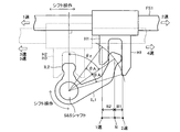
- the engaging portion of the inner lever passes through the rotation center of the S & S shaft and the fork shaft from the rotation center. It is located on a “straight line” tilted by a predetermined angle ( ⁇ z) with respect to a perpendicular line directed toward.
- the engaging portion of the inner lever is engaged with the concave portion of the shift head integrally connected to the fork shaft, so that the engaging portion of the inner lever drives the fork shaft in the axial direction.
- the manual transmission according to the present invention includes a plurality of fixed gears that are provided on the input shaft or the output shaft so as not to rotate relative to each other, and each of the plurality of fixed gears corresponds to each of the plurality of shift stages.
- a plurality of idle gears (G1o, G2o, G3o, G4o, G5o) that are always meshed with the fixed gears of the corresponding gears, and each of which rotates relative to the corresponding shaft of the input shaft and the output shaft.
- a plurality of sleeves provided so as not to be movable relative to each other in the axial direction, each of the plurality of idler gears corresponding to the corresponding idler gear with respect to the corresponding shaft;
- a plurality of sleeves (S1, S2, S3) that can be engaged with the corresponding idler gears to be fixed to the plurality of sleeves, and a plurality of fork shafts that are connected to each of the plurality of sleeves and are movable in the axial direction. (FS1, FS2, FS3).
- the “specific sleeve” corresponds to one or more of the plurality of sleeves
- the “specific fork shaft” corresponds to one or more of the plurality of fork shafts.
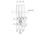
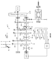
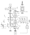
- FIG. 1 is a schematic configuration diagram in a state where an N position of a power transmission control device including a manual transmission for an HV-MT vehicle according to an embodiment of the present invention is selected.
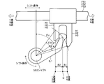
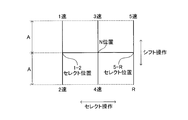
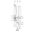
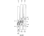
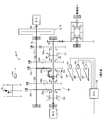
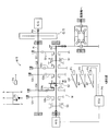
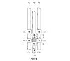
- FIG. It is the schematic diagram which showed the positional relationship of the S & S shaft and the some fork shaft in the state where N position was selected. It is the schematic diagram which showed the engagement state of the "fork shaft” and the “inner lever”. It is the figure which showed the detail of the shift pattern. It is a figure corresponding to Drawing 1 in the state where the 1st speed position was selected. It is a figure corresponding to Drawing 2 in the state where the 1st speed position was selected. It is a figure corresponding to Drawing 1 in the state where the 2nd gear position was selected.
- the present apparatus is “a manual transmission M / T having an engine E / G and a motor generator M / G as a power source and not having a torque converter, a friction clutch C / T, It is applied to a “vehicle equipped with a vehicle”, that is, a so-called “HV-MT vehicle”.
- the “HV-MT vehicle” may be a front wheel drive vehicle, a rear wheel drive vehicle, or a four wheel drive vehicle.
- this device is applied to a vehicle (that is, a normal MT vehicle) having only the engine E / G as a power source and having a manual transmission M / T and a friction clutch C / T. It goes without saying.
- the engine E / G is a well-known internal combustion engine, for example, a gasoline engine that uses gasoline as fuel, or a diesel engine that uses light oil as fuel.
- the manual transmission M / T is a transmission (so-called manual transmission) that does not include a torque converter that selects a gear position according to the shift position of the shift lever SL operated by the driver.
- the M / T includes an input shaft Ai that receives power from the output shaft Ae of the E / G, and an output shaft Ao that receives power from the M / G and outputs power to the driving wheels of the vehicle.
- the input shaft Ai and the output shaft Ao are arranged in parallel to each other.
- the output shaft Ao may be the M / G output shaft itself, or is parallel to the M / G output shaft and connected to the M / G output shaft via a gear train so that power can be transmitted at all times. It may be an axis. Details of the configuration of the M / T will be described later.
- the friction clutch C / T is interposed between the E / G output shaft Ae and the M / T input shaft Ai.
- C / T rotates integrally with Ai with respect to the state of engagement of the friction plates (more specifically, the flywheel that rotates integrally with Ae) according to the operation amount (depression amount) of the clutch pedal CP operated by the driver.
- This is a known clutch in which the axial position of the friction plate changes.
- the C / T joined state (the axial position of the friction plate) is mechanically controlled according to the operation amount of the CP using a link mechanism or the like that mechanically connects the clutch pedal CP and the C / T (friction plate). Or may be adjusted electrically (in a so-called by-wire method) using the driving force of an actuator that operates based on the detection result of a sensor (sensor P1 to be described later) that detects the amount of operation of the CP. May be.
- the motor generator M / G has one of known configurations (for example, an AC synchronous motor), and for example, a rotor (not shown) rotates integrally with the output shaft Ao. That is, a power transmission system is always established between the M / G output shaft and the M / T output shaft Ao.
- EG torque the drive torque of the E / G output shaft Ae
- MG torque the drive torque of the M / G output shaft (output shaft Ao)
- this device has a clutch operation amount sensor P1 that detects an operation amount (depression amount, clutch stroke, etc.) of the clutch pedal CP, and a brake operation amount that detects an operation amount (stepping force, presence / absence of operation, etc.) of the brake pedal BP.
- a sensor P2 an accelerator operation amount sensor P3 that detects the operation amount (accelerator opening) of the accelerator pedal AP, and a shift position sensor P4 that detects the position of the shift lever SL are provided.
- this device includes an electronic control unit ECU.
- the ECU controls the EG torque by controlling the fuel injection amount of the E / G (the opening degree of the throttle valve) based on the information from the sensors P1 to P4 and the other sensors, and the inverter.
- the MG torque is controlled by controlling (not shown).
- shift operation As shown in FIG. 4, a so-called “H pattern” is employed as the shift pattern of the shift lever SL.
- select operation the operation of the shift lever SL in the vehicle left-right direction
- shift operation the operation of the shift lever SL in the vehicle front-rear direction
- “1st speed” and “2nd speed” shift completion positions, “3rd speed” and “4th speed” shift completion positions, and “5th speed” shift completion positions are respectively 1-2 selected.
- the position, the N position, and the 5-R select position are at a position separated by a distance A in the shift operation direction (vehicle longitudinal direction).
- a range of shift positions corresponding to a select operation range including “N position”, “1-2 select position”, and “5-R select position” is collectively referred to as “neutral range”.
- M / T includes sleeves S1, S2, and S3.
- S1, S2 and S3 are sleeves for "1st to 2nd speeds" respectively fitted to corresponding hubs that rotate integrally with the output shaft Ao so that they cannot be rotated relative to each other but can move in the axial direction.
- the sleeves S1, S2, and S3 are integrally connected to the fork shafts FS1, FS2, and FS3 shown in FIGS. 2 and 3 (through corresponding forks), respectively.
- FS1 to FS3 are arranged in parallel to each other.
- Each of FS1, FS2, and FS3 (and therefore S1, S2, and S3) is pivoted by an inner lever IL (see FIGS. 2 and 3) that is integrally provided on the S & S shaft that is interlocked with the operation of the shift lever SL. It is driven in the direction (vertical direction in FIG. 2 and horizontal direction in FIGS. 1 and 3).
- the S & S shaft moves in parallel in the axial direction by a select operation of the shift lever SL (left / right operation in FIGS. 1 and 4), and is moved by the shift operation of the shift lever SL (up / down operation in FIGS. 1 and 4). It is designed to rotate around the center (shift rotation type).
- the S & S shaft and the fork shafts FS1 to FS3 are arranged so as to be perpendicular to each other and have a torsional position relationship.
- FIG. 3 shows the rotation position of the S & S shaft when the shift lever SL is in the neutral range.
- this rotational position is referred to as a “reference position”.
- the engaging portion (tip portion) of the inner lever IL is “the rotation center of the S & S shaft.
- the engaging portion of the inner lever IL is engaged with the concave portion of the shift head H1 that is integrally connected to the FS1 when the shift lever SL is in the 1-2 select position, and is integrated with the FS2 when the SL is in the N position.
- the engaging portion of the IL selectively drives the FS1, FS2, and FS3 in the axial direction.
- neutral positions the axial positions of FS1, FS2, and FS3 when the rotational position of the S & S shaft is at the reference position are referred to as “neutral positions”.
- the SL moves from the 1-2 select position to the “second gear shift completion position” or from the N position to the “fourth gear shift completion position” (that is, moves to the rear side of the vehicle by the distance A).
- the rotational position of the S & S shaft moves from the reference position to the position (second speed position, fourth speed position) rotated clockwise by the angle ⁇ A in FIG.
- the axial position of FS1 (accordingly, S1) or FS2 (accordingly, S2) moves from the neutral position to the position shifted to the right in FIG. 3 by the distance B1 (second speed position, fourth speed position).
- B2> B1 holds. That is, even if the rotation angle of the IL from the reference position is the same counterclockwise and clockwise, the amount of movement in the axial direction of FS1, FS2, and FS3 (thus, S1, S2, and S3) differs. As described above, this is based on the fact that the engaging portion of the IL is positioned on a straight line inclined by a predetermined angle ⁇ z with respect to the “perpendicular”. As described above, each of S1 to S3 corresponds to the “specific sleeve”, each of FS1 to FS3 corresponds to the “specific fork shaft”, and each of H1 to H3 corresponds to the “specific shift head”. . Hereinafter, each shift stage will be described in order.
- the ratio of the rotational speed of Ai to the rotational speed of Ao is called “MT reduction ratio”
- the MT reduction ratio (from the 1st speed to the 5th speed) ( The number of teeth of GNo / the number of teeth of GNi) (N: 1 to 5) gradually decreases.
- the E / G control by this apparatus is generally performed as follows.
- the E / G is maintained in a stopped state (a state in which fuel injection is not performed).
- the E / G stop state the E / G is started (fuel injection is started based on the selection of a gear position for HV traveling (any one of “1st speed” to “5th speed”)).
- the EG torque is controlled based on the accelerator opening and the like.
- the E / G is maintained in the stopped state again based on the selection of “N” or the stop of the vehicle.
- the manual transmission described in the “Background Art” column that is, “one direction side of the fork shaft when the rotational position of the S & S shaft rotates by a first angle from the reference position to the one direction side”
- the distance traveled to the opposite direction side of the fork shaft when the rotational position of the S & S shaft rotates by the first angle from the reference position to the opposite direction side is the same.
- the entire movement range in the axial direction of the fork shaft can be shortened.
- the transmission housing can be further downsized.
- the present invention is not limited to the above embodiment, and various modifications can be employed within the scope of the present invention.
- the sleeves S1 to S3 are all provided on the input shaft Ai, but the sleeves S1 to S3 may be provided on the output shaft Ao. Further, a part of the sleeves S1 to S3 may be provided on the output shaft Ao and the rest on the input shaft Ai. M / G may be omitted.
- the axial positions of the sleeves S1 to S3 are adjusted using the link mechanism (S & S shaft and fork shaft) that mechanically connects the shift lever SL and the sleeves S1 to S3. It is mechanically adjusted according to the shift position.
- the axial positions of the sleeves S1 to S3 may be adjusted electrically (in a so-called by-wire system) using the driving force of the actuator that operates based on the detection result of the shift position sensor P4. .
- all of the fork shafts FS1 to FS3 are the inner lever IL of the S & S shaft (that is, when the rotation position of the S & S shaft is at the reference position, the engaging portion thereof is at a predetermined angle with respect to the “perpendicular”. It is driven by an inner lever located on a straight line inclined by ⁇ z. That is, all of S1 to S3 correspond to the “specific sleeve”, all of FS1 to FS3 correspond to the “specific fork shaft”, and all of H1 to H3 correspond to the “specific shift head”. .
- FS1 is driven by the first inner lever IL1 of the S & S shaft (the same as the inner lever IL shown in FIG. 3), and FS2 and FS3 are driven by the second inner lever IL2 of the S & S shaft.
- the engaging portion of IL2 is located on the “perpendicular line” when the rotation position of the S & S shaft is at the reference position. Therefore, when the rotation position of the S & S shaft is rotated by a first angle from the reference position to the one direction side, the movement distance of the FS2, FS3 to the one direction side, and the rotation position of the S & S shaft is the opposite direction side from the reference position.
- FS2 (or FS3) is driven by the first inner lever IL1 of the S & S shaft (see FIG. 15), and FS1 and FS3 (or FS1 and FS2) are driven by the second inner lever IL2 of the S & S shaft (see FIG. 15). It may be driven.
- S2 (or S3) of S1 to S3 corresponds to the “specific sleeve”
- FS2 (or FS3) of FS1 to FS3 corresponds to the “specific fork shaft”
- H2 of H1 to H3. (Or H3) corresponds to the “specific shift head”.
Landscapes
- Engineering & Computer Science (AREA)
- Mechanical Engineering (AREA)
- Chemical & Material Sciences (AREA)
- Combustion & Propulsion (AREA)
- Transportation (AREA)
- Automation & Control Theory (AREA)
- General Engineering & Computer Science (AREA)
- Gear-Shifting Mechanisms (AREA)
Abstract
L'invention porte sur une boîte de vitesses manuelle. Lorsque la position de rotation d'un axe de passage et sélection (S&S) est dans la position standard, la partie d'attaque d'un levier intérieur (IL) est positionnée au-dessus de la « ligne droite inclinée seulement d'un angle prescrit (θz) par rapport à une ligne perpendiculaire (Z). » L'exécution d'une manœuvre de passage de rapport, de la position de sélection correspondante jusqu'à la « position de passage de rapport complet du premier rapport (ou troisième, cinquième rapport) » fait tourner la position de rotation de l'axe S&S seulement d'un angle (θA) dans le sens inverse de celui des aiguilles d'une montre à partir de la position standard, et déplace l'axe de fourchette (FS1 (ou FS2, FS3)) seulement d'une distance (B2) vers la gauche à partir de la position de point mort. L'exécution d'une manœuvre de passage de rapport depuis la position de sélection correspondante jusqu'à la « position de passage complet du deuxième rapport (ou du quatrième rapport) » fait seulement tourner la position de rotation de l'axe S&S d'un angle (θA) dans le sens des aiguilles d'une montre à partir de la position standard et déplace FS1 (ou FS2) seulement d'une distance (B1) vers la droite à partir de la position de point mort. Le résultat est qu'il est possible de réaliser une boîte de vitesses manuelle utilisée dans un véhicule à boîte de vitesses manuelle qui utilise la grille en H comme grille de passage des rapports, et qui présente une plus petite plage de mouvement totale dans la direction axiale de l'axe de fourchette.
Priority Applications (1)
| Application Number | Priority Date | Filing Date | Title |
|---|---|---|---|
| DE112012001188T DE112012001188T5 (de) | 2011-03-11 | 2012-03-01 | Handschaltgetriebe |
Applications Claiming Priority (2)
| Application Number | Priority Date | Filing Date | Title |
|---|---|---|---|
| JP2011053758A JP2012189156A (ja) | 2011-03-11 | 2011-03-11 | 手動変速機 |
| JP2011-053758 | 2011-03-11 |
Publications (1)
| Publication Number | Publication Date |
|---|---|
| WO2012124494A1 true WO2012124494A1 (fr) | 2012-09-20 |
Family
ID=46830569
Family Applications (1)
| Application Number | Title | Priority Date | Filing Date |
|---|---|---|---|
| PCT/JP2012/055218 Ceased WO2012124494A1 (fr) | 2011-03-11 | 2012-03-01 | Boîte de vitesses manuelle |
Country Status (3)
| Country | Link |
|---|---|
| JP (1) | JP2012189156A (fr) |
| DE (1) | DE112012001188T5 (fr) |
| WO (1) | WO2012124494A1 (fr) |
Families Citing this family (2)
| Publication number | Priority date | Publication date | Assignee | Title |
|---|---|---|---|---|
| KR101765398B1 (ko) | 2015-12-23 | 2017-08-04 | 현대다이모스(주) | 더블 클러치 변속기의 셀렉트 장치 |
| CN113864440B (zh) * | 2021-09-22 | 2024-11-08 | 武汉未来幻影科技有限公司 | 一种适用于手动挡车型的自动换挡装置以及车辆 |
Citations (4)
| Publication number | Priority date | Publication date | Assignee | Title |
|---|---|---|---|---|
| JPH03209064A (ja) * | 1990-01-09 | 1991-09-12 | Kubota Corp | シフトフォークの操作構造 |
| JPH0542822U (ja) * | 1991-11-06 | 1993-06-11 | 本田技研工業株式会社 | 車両用手動変速機 |
| JPH05248539A (ja) * | 1992-03-09 | 1993-09-24 | Kubota Corp | 変速装置の変速操作構造 |
| JPH0932921A (ja) * | 1995-07-17 | 1997-02-07 | Fuji Heavy Ind Ltd | 変速操作機構 |
Family Cites Families (1)
| Publication number | Priority date | Publication date | Assignee | Title |
|---|---|---|---|---|
| JP2010216603A (ja) | 2009-03-18 | 2010-09-30 | Aisin Ai Co Ltd | 手動変速機の操作装置 |
-
2011
- 2011-03-11 JP JP2011053758A patent/JP2012189156A/ja not_active Withdrawn
-
2012
- 2012-03-01 WO PCT/JP2012/055218 patent/WO2012124494A1/fr not_active Ceased
- 2012-03-01 DE DE112012001188T patent/DE112012001188T5/de not_active Withdrawn
Patent Citations (4)
| Publication number | Priority date | Publication date | Assignee | Title |
|---|---|---|---|---|
| JPH03209064A (ja) * | 1990-01-09 | 1991-09-12 | Kubota Corp | シフトフォークの操作構造 |
| JPH0542822U (ja) * | 1991-11-06 | 1993-06-11 | 本田技研工業株式会社 | 車両用手動変速機 |
| JPH05248539A (ja) * | 1992-03-09 | 1993-09-24 | Kubota Corp | 変速装置の変速操作構造 |
| JPH0932921A (ja) * | 1995-07-17 | 1997-02-07 | Fuji Heavy Ind Ltd | 変速操作機構 |
Also Published As
| Publication number | Publication date |
|---|---|
| JP2012189156A (ja) | 2012-10-04 |
| DE112012001188T5 (de) | 2013-12-12 |
Similar Documents
| Publication | Publication Date | Title |
|---|---|---|
| JP5641610B2 (ja) | 手動変速機 | |
| JP5907676B2 (ja) | 手動変速機 | |
| JP5670222B2 (ja) | 手動変速機 | |
| JP5876242B2 (ja) | 手動変速機 | |
| CN103687740B (zh) | 手动变速器 | |
| JP5801068B2 (ja) | 手動変速機 | |
| JP5802478B2 (ja) | 手動変速機 | |
| US9267573B2 (en) | Manual transmission | |
| US20140202282A1 (en) | Manual transmission | |
| WO2012124494A1 (fr) | Boîte de vitesses manuelle | |
| JP5990023B2 (ja) | 車両の動力伝達制御装置 | |
| WO2012081280A1 (fr) | Dispositif de commande de transmission de puissance pour véhicule | |
| JP2012171595A (ja) | 手動変速機 |
Legal Events
| Date | Code | Title | Description |
|---|---|---|---|
| 121 | Ep: the epo has been informed by wipo that ep was designated in this application |
Ref document number: 12757522 Country of ref document: EP Kind code of ref document: A1 |
|
| DPE1 | Request for preliminary examination filed after expiration of 19th month from priority date (pct application filed from 20040101) | ||
| WWE | Wipo information: entry into national phase |
Ref document number: 112012001188 Country of ref document: DE Ref document number: 1120120011880 Country of ref document: DE |
|
| 122 | Ep: pct application non-entry in european phase |
Ref document number: 12757522 Country of ref document: EP Kind code of ref document: A1 |