WO2012124602A1 - Procédé de prétraitement d'une batterie secondaire lithium-ion - Google Patents
Procédé de prétraitement d'une batterie secondaire lithium-ion Download PDFInfo
- Publication number
- WO2012124602A1 WO2012124602A1 PCT/JP2012/055975 JP2012055975W WO2012124602A1 WO 2012124602 A1 WO2012124602 A1 WO 2012124602A1 JP 2012055975 W JP2012055975 W JP 2012055975W WO 2012124602 A1 WO2012124602 A1 WO 2012124602A1
- Authority
- WO
- WIPO (PCT)
- Prior art keywords
- secondary battery
- ion secondary
- lithium ion
- positive electrode
- lithium
- Prior art date
- Legal status (The legal status is an assumption and is not a legal conclusion. Google has not performed a legal analysis and makes no representation as to the accuracy of the status listed.)
- Ceased
Links
Images
Classifications
-
- H—ELECTRICITY
- H01—ELECTRIC ELEMENTS
- H01M—PROCESSES OR MEANS, e.g. BATTERIES, FOR THE DIRECT CONVERSION OF CHEMICAL ENERGY INTO ELECTRICAL ENERGY
- H01M10/00—Secondary cells; Manufacture thereof
- H01M10/05—Accumulators with non-aqueous electrolyte
- H01M10/052—Li-accumulators
- H01M10/0525—Rocking-chair batteries, i.e. batteries with lithium insertion or intercalation in both electrodes; Lithium-ion batteries
-
- H—ELECTRICITY
- H01—ELECTRIC ELEMENTS
- H01M—PROCESSES OR MEANS, e.g. BATTERIES, FOR THE DIRECT CONVERSION OF CHEMICAL ENERGY INTO ELECTRICAL ENERGY
- H01M10/00—Secondary cells; Manufacture thereof
- H01M10/42—Methods or arrangements for servicing or maintenance of secondary cells or secondary half-cells
- H01M10/44—Methods for charging or discharging
-
- H—ELECTRICITY
- H01—ELECTRIC ELEMENTS
- H01M—PROCESSES OR MEANS, e.g. BATTERIES, FOR THE DIRECT CONVERSION OF CHEMICAL ENERGY INTO ELECTRICAL ENERGY
- H01M4/00—Electrodes
- H01M4/02—Electrodes composed of, or comprising, active material
- H01M4/36—Selection of substances as active materials, active masses, active liquids
- H01M4/48—Selection of substances as active materials, active masses, active liquids of inorganic oxides or hydroxides
- H01M4/50—Selection of substances as active materials, active masses, active liquids of inorganic oxides or hydroxides of manganese
- H01M4/505—Selection of substances as active materials, active masses, active liquids of inorganic oxides or hydroxides of manganese of mixed oxides or hydroxides containing manganese for inserting or intercalating light metals, e.g. LiMn2O4 or LiMn2OxFy
-
- H—ELECTRICITY
- H01—ELECTRIC ELEMENTS
- H01M—PROCESSES OR MEANS, e.g. BATTERIES, FOR THE DIRECT CONVERSION OF CHEMICAL ENERGY INTO ELECTRICAL ENERGY
- H01M4/00—Electrodes
- H01M4/02—Electrodes composed of, or comprising, active material
- H01M4/36—Selection of substances as active materials, active masses, active liquids
- H01M4/48—Selection of substances as active materials, active masses, active liquids of inorganic oxides or hydroxides
- H01M4/52—Selection of substances as active materials, active masses, active liquids of inorganic oxides or hydroxides of nickel, cobalt or iron
- H01M4/525—Selection of substances as active materials, active masses, active liquids of inorganic oxides or hydroxides of nickel, cobalt or iron of mixed oxides or hydroxides containing iron, cobalt or nickel for inserting or intercalating light metals, e.g. LiNiO2, LiCoO2 or LiCoOxFy
-
- Y—GENERAL TAGGING OF NEW TECHNOLOGICAL DEVELOPMENTS; GENERAL TAGGING OF CROSS-SECTIONAL TECHNOLOGIES SPANNING OVER SEVERAL SECTIONS OF THE IPC; TECHNICAL SUBJECTS COVERED BY FORMER USPC CROSS-REFERENCE ART COLLECTIONS [XRACs] AND DIGESTS
- Y02—TECHNOLOGIES OR APPLICATIONS FOR MITIGATION OR ADAPTATION AGAINST CLIMATE CHANGE
- Y02E—REDUCTION OF GREENHOUSE GAS [GHG] EMISSIONS, RELATED TO ENERGY GENERATION, TRANSMISSION OR DISTRIBUTION
- Y02E60/00—Enabling technologies; Technologies with a potential or indirect contribution to GHG emissions mitigation
- Y02E60/10—Energy storage using batteries
-
- Y—GENERAL TAGGING OF NEW TECHNOLOGICAL DEVELOPMENTS; GENERAL TAGGING OF CROSS-SECTIONAL TECHNOLOGIES SPANNING OVER SEVERAL SECTIONS OF THE IPC; TECHNICAL SUBJECTS COVERED BY FORMER USPC CROSS-REFERENCE ART COLLECTIONS [XRACs] AND DIGESTS
- Y02—TECHNOLOGIES OR APPLICATIONS FOR MITIGATION OR ADAPTATION AGAINST CLIMATE CHANGE
- Y02P—CLIMATE CHANGE MITIGATION TECHNOLOGIES IN THE PRODUCTION OR PROCESSING OF GOODS
- Y02P70/00—Climate change mitigation technologies in the production process for final industrial or consumer products
- Y02P70/50—Manufacturing or production processes characterised by the final manufactured product
Definitions
- the present invention relates to a pretreatment method for a lithium ion secondary battery using a solid solution system material made of a lithium composite oxide as a positive electrode active material. Moreover, it is related with the lithium ion secondary battery processed by this pre-processing method.
- solid solution positive electrode material has attracted attention as a positive electrode material that may satisfy such requirements.
- the electrochemically inactive layered Li 2 MnO 3 and the electrochemically active layered LiMO 2 (wherein M is a transition metal such as Co or Ni) Solid solutions are expected to exhibit large electrical capacities exceeding 200 mAh / g.
- the lower limit voltage is set to 2.0 V
- the upper limit voltage is set to 4.5 V
- 4.6 V at a current density of 0.2 mA / cm 2 (equivalent to 1 / 12C).
- 4.7V, 4.8V, and charging / discharging in a stepwise manner have been proposed (see Patent Document 1).
- Patent Document 1 that employs the method of repeating the charge / discharge treatment while increasing the upper limit voltage stepwise, although the cycle characteristics can be greatly improved, for example, an extremely long treatment time exceeding 5 days is required. There was a problem that it took.
- an object of the present invention is to provide a pretreatment method of a lithium ion secondary battery that can obtain an effect equivalent to or better than the pretreatment described above in a short time.
- the pretreatment method of the lithium ion secondary battery of the present invention includes a step of preparing a lithium ion secondary battery containing a positive electrode active material represented by the following chemical formula 1: [Formula 1] aLi [Li 1/3 Mn 2/3 ] O 2.
- LiMO 2 (A in the formula is a numerical value greater than 0 and less than 1, and LiMO 2 is a lithium composite oxide containing Ni and Mn) Charging the upper limit potential of the lithium ion secondary battery to 4.5 V or more and less than 5.0 V in terms of a lithium counter electrode, and discharging the lower limit potential to less than 4.0 V in terms of a lithium counter electrode. .
- the charging and discharging are performed at a current rate of 0.1 C or more and 1.3 C or less.
- the lithium ion secondary battery of the present invention is characterized by being processed by the pretreatment method of the present invention.
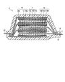
- FIG. 1 is a schematic cross-sectional view showing an example of a lithium ion secondary battery according to an embodiment of the present invention.
- Pretreatment method of lithium ion secondary battery A pretreatment method for a lithium ion secondary battery according to an embodiment of the present invention will be described in detail.
- the pretreatment method of this embodiment is performed on a lithium ion secondary battery using a solid solution system positive electrode active material represented by the following chemical formula 1.
- LiMO 2 (A in the formula is a numerical value greater than 0 and less than 1, and LiMO 2 is a lithium composite oxide containing Ni and Mn) That is, the upper limit potential is 4.5 V or more and less than 5.0 V converted to the lithium counter electrode, the lower limit potential is also converted to the lithium counter electrode and less than 4.0 V, and the current rate is in the range of 0.1 C to 1.3 C.
- Perform charge / discharge treatment By using such a charge / discharge rate, the processing time can be significantly shortened while maintaining the effect obtained by the pre-charge / discharge pretreatment characterized by increasing the conventional upper limit voltage stepwise.
- the lower limit potential during charging and discharging is 4.0 V or more, sufficient Li is not inserted. Therefore, it is considered that an appropriate structural change that should occur in the positive electrode active material is suppressed, and as a result, the effect of improving the cycle durability by the pretreatment is greatly reduced. Therefore, it is preferable to discharge with the lower limit potential being less than 4.0V.
- the upper limit potential during charging is less than 4.5V, the positive electrode active material is not electrochemically activated.
- the upper limit potential is 5.0V or more, the electrolyte used is decomposed. There arises a problem that the battery characteristics deteriorate. Therefore, the upper limit potential is preferably 4.5 V or more and less than 5.0 V.
- the charge / discharge rate is preferably 0.1 C or more and 1.3 C or less.
- the mechanism by which the charge / discharge rate affects the effects of the present invention has not yet been clarified, but is considered as follows.
- the crystal structure of the positive electrode material is disturbed by the process of charging at 4.5 V or higher.
- This disorder of the crystal structure originates from the fact that oxygen ions constituting the crystal at the positive electrode are partially oxidized by charge / discharge and a part thereof is released out of the crystal.
- the solid solution positive electrode active material is activated and a high capacity can be developed, such a charge / discharge process is an essential process for increasing the capacity of the battery.
- the repair mechanism of this crystal structure depends not only on the amount of Li + returning into the crystal but also on the return speed.
- the amount of Li + returning into the crystal depends on the lower limit potential, and the return speed depends on the current rate.
- the pretreatment method for a lithium ion secondary battery of the present invention it is desirable to repeat the charge / discharge treatment at least several times.
- the degree of damage to the crystal structure accompanying the oxidation of oxygen ions due to charging at 4.5 V or more may be increased and may not be repaired. Therefore, it is preferable to perform the process partially in a plurality of times.
- the upper limit potential is increased stepwise when charging and discharging are repeated, that is, the upper limit potential is initially started from a relatively low potential. It is desirable to gradually increase the upper limit potential until a predetermined potential of less than 0V is reached.
- the effect of reducing the pretreatment time while avoiding a sudden change in the crystal structure of the positive electrode active material and maintaining the battery cycle durability at a high level is more certain.
- the pretreatment method of the present invention When the pretreatment method of the present invention is applied to the assembled lithium ion secondary battery, first, the upper and lower potentials for charging and discharging are determined. These potentials need to be values converted to the lithium counter electrode based on the charge and discharge curves of the positive and negative electrodes measured in advance.
- the potential control method may be performed using a reference electrode.
- control may be performed with an electric quantity corresponding to the electric quantity of each charge / discharge when the potential is controlled. In that case, if batteries of the same standard are connected in series, a large number of batteries can be activated at once by this electric quantity control method.
- the lithium ion secondary battery 1 of the present invention uses a solid solution system material represented by the following chemical formula 1 as a positive electrode active material.
- LiMO 2 (A in the formula is a numerical value greater than 0 and less than 1, and LiMO 2 is a lithium composite oxide containing Ni and Mn)
- the lithium ion secondary battery 1 of this invention performs a charging / discharging process by the above upper limit and lower limit electric potential range, and a charging / discharging rate as a pretreatment after a battery assembly. Due to the effect of the pretreatment described above, the lithium ion secondary battery 1 of the present invention can be obtained in a short time and exhibits excellent cycle durability.
- FIG. 1 shows an example of a lithium ion secondary battery according to an embodiment of the present invention.
- the lithium ion secondary battery 1 of this embodiment has a configuration in which a battery element 10 to which a positive electrode tab 21 and a negative electrode tab 22 are attached is enclosed in an exterior body 30.
- the positive electrode tab 21 and the negative electrode tab 22 are led out in the opposite directions from the inside of the exterior body 30 toward the outside.
- the positive electrode tab and the negative electrode tab may be led out in the same direction from the inside of the exterior body toward the outside.
- such a positive electrode tab and a negative electrode tab can be attached to the positive electrode collector and negative electrode collector which are mentioned later by ultrasonic welding, resistance welding, etc., for example.
- the positive electrode tab 21 and the negative electrode tab 22 are made of materials such as aluminum (Al), copper (Cu), titanium (Ti), nickel (Ni), stainless steel (SUS), and alloys thereof.
- the material is not limited thereto, and a conventionally known material that can be used as a tab for a lithium ion secondary battery can be used.
- the positive electrode tab and the negative electrode tab may be made of the same material or different materials.
- a separately prepared tab may be connected to a positive electrode current collector and a negative electrode current collector described later, and each positive electrode current collector and each negative electrode current collector described later are in a foil shape. In some cases, tabs may be formed by extending each one.
- the said exterior body 30 is formed with the film-shaped exterior material from a viewpoint of size reduction and weight reduction, for example.
- the film-shaped exterior material from a viewpoint of size reduction and weight reduction, for example.
- the conventionally well-known material which can be used for the exterior body for lithium ion secondary batteries can be used.
- a polymer-metal composite laminate sheet with excellent thermal conductivity should be used to efficiently transfer heat from the heat source of the automobile and to quickly heat the inside of the battery to the battery operating temperature. Is preferred.
- the battery element 10 in the lithium ion secondary battery 1 of the present embodiment has a configuration in which a plurality of unit cell layers 14 including a positive electrode 11, an electrolyte layer 13, and a negative electrode 12 are stacked. Yes.
- the positive electrode 11 has a configuration in which a positive electrode active material layer 11B is formed on both main surfaces of the positive electrode current collector 11A.
- the negative electrode 12 has a configuration in which a negative electrode active material layer 12B is formed on both main surfaces of the negative electrode current collector 12A.
- the negative electrode active material layer 12 ⁇ / b> B formed on the opposite side is opposed to the electrolyte layer 13.
- a plurality of positive electrodes, electrolyte layers, and negative electrodes are laminated in this order, and the adjacent positive electrode active material layer 11B, electrolyte layer 13, and negative electrode active material layer 12B constitute one single battery layer. That is, the lithium ion secondary battery 1 according to the present embodiment has a configuration in which a plurality of single battery layers 14 are stacked and electrically connected in parallel.
- the negative electrode current collector 12A located on the outermost layer of the battery element 10 has a negative electrode active material layer 12B formed only on one side.
- an insulating layer may be provided on the outer periphery of the unit cell layer 14 in order to insulate between the adjacent positive electrode current collector and negative electrode current collector.
- Such an insulating layer is preferably formed on the outer periphery of the unit cell layer by a material capable of holding the electrolyte contained in the electrolyte layer and preventing electrolyte leakage.
- general-purpose plastics such as polypropylene (PP), polyethylene (PE), polyurethane (PUR), polyamide resin (PA), polytetrafluoroethylene (PTFE), polyvinylidene fluoride (PVdF), and polystyrene (PS) Can be used.
- thermoplastic olefin rubber, silicone rubber, etc. can also be used.
- the positive electrode current collector 11A and the negative electrode current collector 12A are made of a conductive material such as foil or mesh aluminum, copper, stainless steel (SUS), for example.
- the material is not limited to these, and a conventionally known material that can be used as a current collector for a lithium ion secondary battery can be used.
- the size of the current collector can be determined according to the intended use of the battery. For example, if it is used for a large battery that requires a high energy density, a current collector having a large area is used.
- the thickness of the current collector is usually about 1 to 100 ⁇ m.
- the shape of the current collector is not particularly limited.
- a mesh shape (expanded grid or the like) can be used.
- the thin film alloy which is a negative electrode active material directly on the negative electrode collector 12A by sputtering method etc. it is desirable to use current collection foil.
- a metal or a resin in which a conductive filler is added to a conductive polymer material or a non-conductive polymer material can be employed.
- the metal include aluminum, nickel, iron, stainless steel, titanium, and copper.
- covered on the metal surface may be sufficient.
- aluminum, stainless steel, copper, and nickel are preferable from the viewpoints of electronic conductivity, battery operating potential, and adhesion of the negative electrode active material by sputtering to the current collector.
- the conductive polymer material examples include polyaniline, polypyrrole, polythiophene, polyacetylene, polyparaphenylene, polyphenylene vinylene, polyacrylonitrile, and polyoxadiazole. Since such a conductive polymer material has sufficient conductivity without adding a conductive filler, it is advantageous in terms of facilitating the manufacturing process or reducing the weight of the current collector.
- Non-conductive polymer materials include, for example, polyethylene (PE; high density polyethylene (HDPE), low density polyethylene (LDPE), etc.), polypropylene (PP), polyethylene terephthalate (PET), polyether nitrile (PEN), polyimide (PI), polyamideimide (PAI), polyamide (PA), polytetrafluoroethylene (PTFE), styrene-butadiene rubber (SBR), polyacrylonitrile (PAN), polymethyl acrylate (PMA), polymethyl methacrylate (PMMA) , Polyvinyl chloride (PVC), polyvinylidene fluoride (PVdF), polystyrene (PS), and the like.
- PE polyethylene
- HDPE high density polyethylene
- LDPE low density polyethylene
- PP polypropylene
- PET polyethylene terephthalate
- PEN polyether nitrile
- PI polyimide
- PAI polyamideimide
- PA polyamide
- PTFE polyt
- a conductive filler can be added to the conductive polymer material or the non-conductive polymer material as necessary.
- a conductive filler is essential to impart conductivity to the resin.
- the conductive filler can be used without particular limitation as long as it is a substance having conductivity.
- a metal, conductive carbon, etc. are mentioned as a material excellent in electroconductivity, electric potential resistance, or lithium ion interruption
- the metal is not particularly limited, but includes at least one metal selected from the group consisting of Ni, Ti, Al, Cu, Pt, Fe, Cr, Sn, Zn, In, Sb, and K, or these metals.
- the conductive carbon is not particularly limited, but preferably acetylene black, Vulcan (registered trademark), black pearl (registered trademark), carbon nanofiber, ketjen black (registered trademark), carbon nanotube, carbon nanohorn, carbon It contains at least one selected from the group consisting of nanoballoons and fullerenes.
- the amount of the conductive filler added is not particularly limited as long as it is an amount capable of imparting sufficient conductivity to the current collector, and is generally about 5 to 35% by mass of the entire current collector.
- the material is not limited to these, and a conventionally known material used as a current collector for a lithium ion secondary battery can be used.
- the positive electrode is configured by forming a positive electrode active material layer on one or both sides of a positive electrode current collector made of a conductive material such as an aluminum foil, a copper foil, a nickel foil, or a stainless steel foil.
- the positive electrode active material layer 11B includes any one or more of positive electrode materials capable of inserting and extracting lithium as a positive electrode active material, and includes a conductive auxiliary agent and a binder as necessary. May be. In addition, it is not specifically limited as a compounding ratio of these positive electrode active materials, a conductive support agent, and a binder in a positive electrode active material layer.
- a solid solution system material represented by the following chemical formula 1 is used as the positive electrode active material.
- LiMO 2 (A in the formula is a numerical value greater than 0 and less than 1, and LiMO 2 is a lithium composite oxide containing Ni and Mn)
- Examples of such known positive electrode active materials include lithium-transition metal composite oxides, lithium-transition metal phosphate compounds, lithium-transition metal sulfate compounds, ternary systems, NiMn systems, NiCo systems, and spinel Mn systems. Can be mentioned.
- the positive electrode active material made of the solid solution system material represented by the above chemical formula 1 for example, a material synthesized by a solid phase method or a solution method can be used.
- the solution method include a mixed hydroxide method, a composite carbonate method, and an organic acid method.
- it can be produced by a general synthesis method such as a coprecipitation method, a sol-gel method, or a PVA method.
- the lithium composite oxide represented by LiMO 2 contains Ni and Mn as essential components.
- one or more transition metals selected from Co, Al, Ti, Fe, Cu, Mg and the like can also be contained.
- the addition of Co can be expected to improve the conductivity of the active material, and the addition of Al, Ti, Fe, Cu, Mg can be expected to improve the durability by stabilizing the crystal structure.
- the particle size of the positive electrode active material is not particularly limited, but generally finer is more desirable.
- the average particle diameter may be about 1 to 30 ⁇ m, and more preferably about 5 to 20 ⁇ m.
- lithium-transition metal composite oxide examples include LiMn 2 O 4 , LiCoO 2 , LiNiO 2 , Li (Ni, Mn, Co) O 2 , Li (Li, Ni, Mn, Co) O 2 , LiFePO 4 and Examples include those in which some of these transition metals are substituted with other elements.
- Examples of the ternary system include nickel / cobalt / manganese composite cathode materials.
- spinel Mn system include LiMn 2 O 4 .
- NiMn system examples include LiNi 0.5 Mn 1.5 O 4 .
- NiCo system examples include Li (NiCo) O 2 .
- the optimum particle diameters may be blended and used for expressing each unique effect. That is, it is not always necessary to make the particle sizes of all the active materials uniform.
- the binder is added for the purpose of maintaining the electrode structure by binding the active materials or the active material and the current collector.
- a binder examples include polyvinylidene fluoride (PVDF), polytetrafluoroethylene (PTFE), polyvinyl acetate, polyimide (PI), polyamide (PA), polyvinyl chloride (PVC), polymethyl acrylate (PMA), Thermosetting resins such as polymethyl methacrylate (PMMA), polyether nitrile (PEN), polyethylene (PE), polypropylene (PP) and polyacrylonitrile (PAN), epoxy resins, polyurethane resins, and urea resins
- rubber-based materials such as styrene butadiene rubber (SBR) can be used.
- the conductive assistant is also referred to as a conductive agent, and refers to a conductive additive that is blended to improve conductivity.
- the conductive auxiliary agent used in the present invention is not particularly limited, and conventionally known ones can be used.
- carbon materials such as carbon black such as acetylene black, graphite, and carbon fiber can be given.
- a conductive additive By containing a conductive additive, an electronic network inside the active material layer is effectively formed, which contributes to improving the output characteristics of the battery and improving reliability by improving the liquid retention of the electrolytic solution.
- the negative electrode is configured by forming a negative electrode active material layer on one side or both sides of a negative electrode current collector made of a conductive material as described above, similarly to the positive electrode.
- the negative electrode active material layer 12B includes one or more negative electrode materials capable of occluding and releasing lithium as the negative electrode active material, and, if necessary, the above-described positive electrode active material.
- the same conductive assistant and binder may be included. In addition, it is not specifically limited as a compounding ratio of these negative electrode active materials, a conductive support agent, and a binder in a negative electrode active material layer.
- the negative electrode active material applied to the lithium ion secondary battery of the present invention is not particularly limited as long as it can reversibly occlude and release lithium, and a conventionally known negative electrode active material can be used.
- Other negative electrode active materials include, for example, graphite (natural graphite, artificial graphite, etc.), which is highly crystalline carbon, low crystalline carbon (soft carbon, hard carbon), carbon black (Ketjen black, acetylene black, channel black) , Lamp black, oil furnace black, thermal black, etc.), carbon materials such as fullerene, carbon nanotube, carbon nanofiber, carbon nanohorn, and carbon fibril.
- the negative electrode active material Si, Ge, Sn, Pb, Al, In, Zn, H, Ca, Sr, Ba, Ru, Rh, Ir, Pd, Pt, Ag, Au, Cd, Hg, Ga, Tl , C, N, Sb, Bi, O, S, Se, Te, Cl, and the like
- oxides include silicon monoxide (SiO), SiO x (0 ⁇ x ⁇ 2), tin dioxide (SnO 2 ), SnO x (0 ⁇ x ⁇ 2), SnSiO 3 and the like.
- the carbide include silicon carbide (SiC).
- examples of the negative electrode active material include metal materials such as lithium metal and lithium-transition metal composite oxides such as lithium-titanium composite oxide (lithium titanate: Li 4 Ti 5 O 12 ).
- these negative electrode active materials can be used alone or in the form of a mixture of two or more.
- the positive electrode active material layer and the negative electrode active material layer are formed on one surface or both surfaces of each current collector, as described above.
- the negative electrode active material layer can also be formed on the other surface.
- Such an electrode can be applied to a bipolar battery.
- the electrolyte layer is a layer containing a non-aqueous electrolyte.
- the non-aqueous electrolyte contained in the electrolyte layer functions as a lithium ion carrier that moves between the positive and negative electrodes during charge and discharge.
- the thickness of the electrolyte layer is preferably as thin as possible from the viewpoint of reducing internal resistance, and is usually in the range of about 1 to 100 ⁇ m, preferably 5 to 50 ⁇ m.
- the nonaqueous electrolyte is not particularly limited as long as it can exhibit such a function, and a liquid electrolyte or a polymer electrolyte can be used.
- the liquid electrolyte has a form in which a lithium salt (electrolyte salt) is dissolved in an organic solvent.
- organic solvent include ethylene carbonate (EC), propylene carbonate (PC), butylene carbonate (BC), vinylene carbonate (VC), dimethyl carbonate (DMC), diethyl carbonate (DEC), ethyl methyl carbonate (EMC), Examples include carbonates such as methylpropyl carbonate (MPC).
- the lithium salt Li (CF 3 SO 2) 2 N, Li (C 2 F 5 SO 2) 2 N, LiPF 6, LiBF 4, LiAsF 6, LiTaF 6, LiClO 4, LiCF 3 SO 3 , etc.
- a compound that can be added to the active material layer of the electrode can be employed.
- polymer electrolytes are classified into a gel polymer electrolyte containing an electrolytic solution (gel electrolyte) and an intrinsic polymer electrolyte containing no electrolytic solution.
- the gel polymer electrolyte is preferably configured by injecting the liquid electrolyte into a matrix polymer (host polymer) made of an ion conductive polymer.
- the ion conductive polymer used as the matrix polymer (host polymer) is not particularly limited.
- the ion conductive polymer may be the same as or different from the ion conductive polymer used as the electrolyte in the active material layer, but is preferably the same.
- the type of the electrolyte solution composed of the lithium salt and the organic solvent is not particularly limited, and an electrolyte salt such as the lithium salt exemplified above and an organic solvent such as carbonates are used.
- Authentic polymer electrolyte has a lithium salt dissolved in the above matrix polymer and does not contain an organic solvent.
- an intrinsic polymer electrolyte as the electrolyte, there is no fear of liquid leakage from the battery, and the reliability of the battery is improved.
- the matrix polymer of the gel polymer electrolyte or the intrinsic polymer electrolyte can exhibit excellent mechanical strength by forming a crosslinked structure.
- a polymerization process such as thermal polymerization, ultraviolet polymerization, radiation polymerization, or electron beam polymerization is performed on a polymerizable polymer for forming a polymer electrolyte using an appropriate polymerization initiator. That's fine.
- the polymer electrolyte resting polymerizable polymer include PEO and PPO.
- the non-aqueous electrolyte contained in these electrolyte layers may be used alone or in combination of two or more.
- a separator is used for the electrolyte layer.
- the separator include a microporous film made of polyolefin such as polyethylene or polypropylene.
- a lithium ion secondary battery has a structure in which a battery element is housed in a battery case such as a can or a laminate container (packaging body).
- the battery element (electrode structure) is configured by connecting a positive electrode and a negative electrode via an electrolyte layer.
- the battery element is roughly divided into a wound type battery having a structure in which a positive electrode, an electrolyte layer and a negative electrode are wound, and a stacked type battery in which a positive electrode, an electrolyte layer and a negative electrode are stacked.
- it may be called what is called a coin cell, a button battery, a laminate battery, etc. according to the shape and structure of a battery case.
- the total amount of the above four kinds of metal acetates and citric acid were accurately weighed so that the molar ratio was 1: 1. These were put into a sample beaker and dissolved in ultrapure water to obtain an aqueous solution. Then, it applied to the spray-drying apparatus and the mixed precursor of the powder was obtained by the spray-drying method. The obtained mixed precursor sample was put in a crucible and calcined at 450 ° C. for 10 hours in the air. Then, it put into the mortar and grind
- the pelletized sample was subjected to main firing in the air at a firing temperature of 900 ° C. for 12 hours in the air with a heating time of 7 hours. Then, quenching (rapid cooling) is performed using liquid nitrogen, and 0.6Li [Li 1/3 Mn 2/3 ] O 2 .0.4Li [Ni 0.4575 Co 0.0825 Mn 0.4575 ] O 2 is used.
- the solid solution positive electrode active material represented was obtained.
- composition ratio of the obtained positive electrode active material sample was confirmed to be the above composition by inductively coupled plasma (ICP) elemental analysis. Further, the crystal structure of the obtained sample was examined by a powder X-ray diffraction method. As a result, it was confirmed that when a superlattice peak with 2 ⁇ of 21 ° to 25 ° was removed, indexing was possible with the space group R-3m, and the above solid solution system compound was obtained.
- ICP inductively coupled plasma
- the metal lithium foil (negative electrode) of diameter 15mm was used as a counter electrode, and the cell was assembled through the glass filter paper as a separator.
- the electrolytic solution a solution containing lithium hexafluorophosphate (LiPF 6 ) in a solvent in which ethylene carbonate (EC) and dimethyl carbonate (DMC) were mixed at a volume ratio of 1: 2 was used.
- EC ethylene carbonate
- DMC dimethyl carbonate
- Example 1 The charge / discharge rate was set to 0.50C. Further, charging was performed at a constant current, with the positive electrode potential being 4.5 V relative to the lithium counter electrode, with the charge upper limit potential. Thereafter, the discharge was performed until the potential of the positive electrode was equivalent to 2.0 V with respect to the lithium counter electrode, with the discharge lower limit potential. This charge / discharge operation was repeated twice. (2) Next, the battery was charged until the potential of the positive electrode reached 4.6 V relative to the lithium counter electrode, with the upper limit potential being charged. Thereafter, the discharge was performed until the potential of the positive electrode was equivalent to 2.0 V with respect to the lithium counter electrode, with the discharge lower limit potential. This charge / discharge operation was repeated twice in the same manner.
- Example 2 A charge / discharge treatment similar to that in Example 1 was performed on the evaluation cell except that the charge / discharge rate was set to 0.33C.
- Example 3 A charge / discharge treatment similar to that of Example 2 was performed on the evaluation cell except that the lower limit discharge potential was set to 3.45V.
- Example 4 The evaluation cell was subjected to the same charge / discharge treatment as in Example 1 except that the discharge lower limit potential was set to 3.00V.
- Example 5 As preconditions, the charge / discharge rate is set to 0.67C, the first two charge upper limit potentials are 4.6V, the next two charge upper limit potentials are 4.7V, and the last two times. was set to 4.8V. Except for these changes, the same charge / discharge treatment as in Example 1 was performed on the evaluation cell.
- Example 1 A charge / discharge treatment similar to that in Example 1 was performed on the evaluation cell except that the charge / discharge rate was set to 0.083C.
- Example 3 A charge / discharge treatment similar to that in Example 1 was performed on the evaluation cell except that the charge / discharge rate was set to 1.33C.
- Comparative Example 4 The same charge / discharge treatment as that of Comparative Example 1 was performed on the evaluation cell, except that the lower limit discharge potential was set to 4.10V.
- the processing conditions for shortening the time required for the pretreatment were found without impairing the effect of the conventional pretreatment corresponding to the result of Comparative Example 1.
- the current rate of the preprocessing is set to be larger than that in the conventional method and within an appropriate numerical range, and the discharge lower limit potential may be set to an appropriate range. That is, the current rate during charge / discharge is a charge / discharge rate of 0.1 C to 1.3 C.
- the upper limit potential is converted to a lithium counter electrode and set to 4.5 V or more and less than 5.0 V
- the lower limit potential is converted to a lithium counter electrode and set to less than 4.0 V. It has been clarified that by performing such pretreatment, it is possible to manufacture a high-energy lithium ion secondary battery excellent in durability with high productivity.
Landscapes
- Chemical & Material Sciences (AREA)
- Chemical Kinetics & Catalysis (AREA)
- Electrochemistry (AREA)
- General Chemical & Material Sciences (AREA)
- Engineering & Computer Science (AREA)
- Inorganic Chemistry (AREA)
- Manufacturing & Machinery (AREA)
- Materials Engineering (AREA)
- Battery Electrode And Active Subsutance (AREA)
- Secondary Cells (AREA)
Abstract
Ce procédé de pré-traitement d'une batterie secondaire lithium-ion comporte : une étape de préparation d'une batterie secondaire lithium-ion contenant la matière active de cathode représentée par la formule chimique (1) ; et une étape de charge avec le potentiel de limite supérieure de la batterie secondaire lithium-ion qui est d'au moins 4,5 V et inférieur à 5,0 V en termes d'une contre-électrode de lithium, et de décharge avec le potentiel de limite inférieure qui est inférieur à 4,0 V en termes d'une contre-électrode de lithium. Egalement, la charge et la décharge sont caractérisées en ce qu'elles sont effectuées à un taux de courant de 0,1-1,3 C inclus. Formule 1 : aLi[Li1/3Mn2/3]O2
.(1-a)LiMO2 (Dans la formule : a est une valeur au-dessus de 0 et inférieure à 1 ; et LiMO2 est un oxyde complexe de lithium contenant Ni et Mn).
Applications Claiming Priority (2)
| Application Number | Priority Date | Filing Date | Title |
|---|---|---|---|
| JP2011-057446 | 2011-03-16 | ||
| JP2011057446A JP2012195126A (ja) | 2011-03-16 | 2011-03-16 | リチウムイオン二次電池の前処理方法 |
Publications (1)
| Publication Number | Publication Date |
|---|---|
| WO2012124602A1 true WO2012124602A1 (fr) | 2012-09-20 |
Family
ID=46830675
Family Applications (1)
| Application Number | Title | Priority Date | Filing Date |
|---|---|---|---|
| PCT/JP2012/055975 Ceased WO2012124602A1 (fr) | 2011-03-16 | 2012-03-08 | Procédé de prétraitement d'une batterie secondaire lithium-ion |
Country Status (2)
| Country | Link |
|---|---|
| JP (1) | JP2012195126A (fr) |
| WO (1) | WO2012124602A1 (fr) |
Cited By (2)
| Publication number | Priority date | Publication date | Assignee | Title |
|---|---|---|---|---|
| WO2013115390A1 (fr) * | 2012-02-01 | 2013-08-08 | 日産自動車株式会社 | Oxyde de métal de transition contenant du lithium en solution solide, cathode de batterie secondaire d'électrolyte non aqueux et batterie secondaire d'électrolyte non aqueux |
| WO2015015894A1 (fr) * | 2013-07-31 | 2015-02-05 | 日産自動車株式会社 | Électrode positive utilisable dans un accumulateur à électrolyte non aqueux et accumulateur à électrolyte non aqueux l'utilisant |
Families Citing this family (2)
| Publication number | Priority date | Publication date | Assignee | Title |
|---|---|---|---|---|
| JP6167775B2 (ja) * | 2013-09-06 | 2017-07-26 | 日産自動車株式会社 | 二次電池の制御装置及び制御方法 |
| WO2016209014A1 (fr) * | 2015-06-26 | 2016-12-29 | 주식회사 엘지화학 | Procédé permettant de fabriquer une batterie rechargeable au lithium et batterie rechargeable au lithium fabriquée à l'aide de ce dernier |
Citations (7)
| Publication number | Priority date | Publication date | Assignee | Title |
|---|---|---|---|---|
| JP2007095443A (ja) * | 2005-09-28 | 2007-04-12 | Sanyo Electric Co Ltd | 非水電解質二次電池 |
| JP2009176533A (ja) * | 2008-01-23 | 2009-08-06 | Toyota Motor Corp | リチウム二次電池の検査方法及び製造方法 |
| JP2010103086A (ja) * | 2008-09-26 | 2010-05-06 | Nissan Motor Co Ltd | リチウムイオン電池用正極 |
| JP2010108873A (ja) * | 2008-10-31 | 2010-05-13 | Nissan Motor Co Ltd | リチウムイオン電池とその使用方法 |
| JP2010129481A (ja) * | 2008-11-28 | 2010-06-10 | Mitsui Mining & Smelting Co Ltd | 非水電解液二次電池用正極 |
| WO2011016113A1 (fr) * | 2009-08-04 | 2011-02-10 | トヨタ自動車株式会社 | Batterie secondaire au lithium-ion à électrolyte non aqueux |
| WO2011078389A1 (fr) * | 2009-12-25 | 2011-06-30 | 株式会社豊田自動織機 | Procédé pour produire un oxyde complexe, un matériau actif d'électrode positive pour une batterie secondaire lithium-ion, et batterie secondaire lithium-ion |
-
2011
- 2011-03-16 JP JP2011057446A patent/JP2012195126A/ja not_active Withdrawn
-
2012
- 2012-03-08 WO PCT/JP2012/055975 patent/WO2012124602A1/fr not_active Ceased
Patent Citations (7)
| Publication number | Priority date | Publication date | Assignee | Title |
|---|---|---|---|---|
| JP2007095443A (ja) * | 2005-09-28 | 2007-04-12 | Sanyo Electric Co Ltd | 非水電解質二次電池 |
| JP2009176533A (ja) * | 2008-01-23 | 2009-08-06 | Toyota Motor Corp | リチウム二次電池の検査方法及び製造方法 |
| JP2010103086A (ja) * | 2008-09-26 | 2010-05-06 | Nissan Motor Co Ltd | リチウムイオン電池用正極 |
| JP2010108873A (ja) * | 2008-10-31 | 2010-05-13 | Nissan Motor Co Ltd | リチウムイオン電池とその使用方法 |
| JP2010129481A (ja) * | 2008-11-28 | 2010-06-10 | Mitsui Mining & Smelting Co Ltd | 非水電解液二次電池用正極 |
| WO2011016113A1 (fr) * | 2009-08-04 | 2011-02-10 | トヨタ自動車株式会社 | Batterie secondaire au lithium-ion à électrolyte non aqueux |
| WO2011078389A1 (fr) * | 2009-12-25 | 2011-06-30 | 株式会社豊田自動織機 | Procédé pour produire un oxyde complexe, un matériau actif d'électrode positive pour une batterie secondaire lithium-ion, et batterie secondaire lithium-ion |
Cited By (2)
| Publication number | Priority date | Publication date | Assignee | Title |
|---|---|---|---|---|
| WO2013115390A1 (fr) * | 2012-02-01 | 2013-08-08 | 日産自動車株式会社 | Oxyde de métal de transition contenant du lithium en solution solide, cathode de batterie secondaire d'électrolyte non aqueux et batterie secondaire d'électrolyte non aqueux |
| WO2015015894A1 (fr) * | 2013-07-31 | 2015-02-05 | 日産自動車株式会社 | Électrode positive utilisable dans un accumulateur à électrolyte non aqueux et accumulateur à électrolyte non aqueux l'utilisant |
Also Published As
| Publication number | Publication date |
|---|---|
| JP2012195126A (ja) | 2012-10-11 |
Similar Documents
| Publication | Publication Date | Title |
|---|---|---|
| JP5357268B2 (ja) | 電気デバイス用正極材料およびこれを用いた電気デバイス | |
| KR101625313B1 (ko) | 전기 디바이스용 부극 활물질 | |
| KR101505351B1 (ko) | 리튬 이온 2차 전지용 정극 활물질 | |
| CN103563134B (zh) | 电气设备用负极活性物质 | |
| CN103548184B (zh) | 电气设备用负极活性物质、电气设备用负极及电气设备 | |
| KR101660100B1 (ko) | 전기 디바이스용 부극 활물질 | |
| WO2012121240A1 (fr) | Matériau actif d'électrode négative pour dispositifs électriques | |
| JP5691315B2 (ja) | リチウムイオン電池用正極およびこれを用いたリチウムイオン電池 | |
| CN103563135B (zh) | 电气设备用负极活性物质 | |
| WO2013099440A1 (fr) | Matière active d'électrode négative destinée à un dispositif électrique, électrode négative destinée à un dispositif électrique et dispositif électrique | |
| WO2013088846A1 (fr) | Matériau actif d'électrode négative pour dispositif électrique | |
| JP2011204563A (ja) | 非水二次電池の製造方法 | |
| CN107112518A (zh) | 电气设备用负极活性物质和使用其的电气设备 | |
| CN111183537A (zh) | 负极活性物质的预掺杂方法、以及电气设备用电极及电气设备的制造方法 | |
| KR101385334B1 (ko) | 리튬 이온 2차 전지용 복합 정극 활물질 및 이것을 사용한 리튬 이온 2차 전지 | |
| CN107112517A (zh) | 电气设备用负极活性物质和使用其的电气设备 | |
| WO2012124602A1 (fr) | Procédé de prétraitement d'une batterie secondaire lithium-ion | |
| JP5626035B2 (ja) | リチウムイオン二次電池の前処理方法及び使用方法 | |
| WO2014199782A1 (fr) | Matériau actif d'anode pour dispositif électrique, et dispositif électrique l'utilisant | |
| WO2013125465A1 (fr) | Matériau actif d'électrode positive | |
| WO2013058091A1 (fr) | Substance active d'électrode négative pour utilisation dans un dispositif électrique |
Legal Events
| Date | Code | Title | Description |
|---|---|---|---|
| 121 | Ep: the epo has been informed by wipo that ep was designated in this application |
Ref document number: 12758280 Country of ref document: EP Kind code of ref document: A1 |
|
| NENP | Non-entry into the national phase |
Ref country code: DE |
|
| 122 | Ep: pct application non-entry in european phase |
Ref document number: 12758280 Country of ref document: EP Kind code of ref document: A1 |