WO2012124657A1 - 走行振動抑制装置を備えた作業車両 - Google Patents
走行振動抑制装置を備えた作業車両 Download PDFInfo
- Publication number
- WO2012124657A1 WO2012124657A1 PCT/JP2012/056295 JP2012056295W WO2012124657A1 WO 2012124657 A1 WO2012124657 A1 WO 2012124657A1 JP 2012056295 W JP2012056295 W JP 2012056295W WO 2012124657 A1 WO2012124657 A1 WO 2012124657A1
- Authority
- WO
- WIPO (PCT)
- Prior art keywords
- height position
- control valve
- bucket
- work
- lift cylinder
- Prior art date
- Legal status (The legal status is an assumption and is not a legal conclusion. Google has not performed a legal analysis and makes no representation as to the accuracy of the status listed.)
- Ceased
Links
Images


Classifications
-
- E—FIXED CONSTRUCTIONS
- E02—HYDRAULIC ENGINEERING; FOUNDATIONS; SOIL SHIFTING
- E02F—DREDGING; SOIL-SHIFTING
- E02F9/00—Component parts of dredgers or soil-shifting machines, not restricted to one of the kinds covered by groups E02F3/00 - E02F7/00
- E02F9/20—Drives; Control devices
- E02F9/22—Hydraulic or pneumatic drives
- E02F9/2203—Arrangements for controlling the attitude of actuators, e.g. speed, floating function
- E02F9/2207—Arrangements for controlling the attitude of actuators, e.g. speed, floating function for reducing or compensating oscillations
-
- B—PERFORMING OPERATIONS; TRANSPORTING
- B60—VEHICLES IN GENERAL
- B60G—VEHICLE SUSPENSION ARRANGEMENTS
- B60G17/00—Resilient suspensions having means for adjusting the spring or vibration-damper characteristics, for regulating the distance between a supporting surface and a sprung part of vehicle or for locking suspension during use to meet varying vehicular or surface conditions, e.g. due to speed or load
- B60G17/015—Resilient suspensions having means for adjusting the spring or vibration-damper characteristics, for regulating the distance between a supporting surface and a sprung part of vehicle or for locking suspension during use to meet varying vehicular or surface conditions, e.g. due to speed or load the regulating means comprising electric or electronic elements
- B60G17/016—Resilient suspensions having means for adjusting the spring or vibration-damper characteristics, for regulating the distance between a supporting surface and a sprung part of vehicle or for locking suspension during use to meet varying vehicular or surface conditions, e.g. due to speed or load the regulating means comprising electric or electronic elements characterised by their responsiveness, when the vehicle is travelling, to specific motion, a specific condition, or driver input
-
- B—PERFORMING OPERATIONS; TRANSPORTING
- B60—VEHICLES IN GENERAL
- B60G—VEHICLE SUSPENSION ARRANGEMENTS
- B60G17/00—Resilient suspensions having means for adjusting the spring or vibration-damper characteristics, for regulating the distance between a supporting surface and a sprung part of vehicle or for locking suspension during use to meet varying vehicular or surface conditions, e.g. due to speed or load
- B60G17/02—Spring characteristics, e.g. mechanical springs and mechanical adjusting means
- B60G17/04—Spring characteristics, e.g. mechanical springs and mechanical adjusting means fluid spring characteristics
-
- E—FIXED CONSTRUCTIONS
- E02—HYDRAULIC ENGINEERING; FOUNDATIONS; SOIL SHIFTING
- E02F—DREDGING; SOIL-SHIFTING
- E02F9/00—Component parts of dredgers or soil-shifting machines, not restricted to one of the kinds covered by groups E02F3/00 - E02F7/00
- E02F9/20—Drives; Control devices
- E02F9/22—Hydraulic or pneumatic drives
- E02F9/2217—Hydraulic or pneumatic drives with energy recovery arrangements, e.g. using accumulators, flywheels
-
- B—PERFORMING OPERATIONS; TRANSPORTING
- B60—VEHICLES IN GENERAL
- B60G—VEHICLE SUSPENSION ARRANGEMENTS
- B60G2300/00—Indexing codes relating to the type of vehicle
- B60G2300/09—Construction vehicles, e.g. graders, excavators
-
- B—PERFORMING OPERATIONS; TRANSPORTING
- B60—VEHICLES IN GENERAL
- B60G—VEHICLE SUSPENSION ARRANGEMENTS
- B60G2400/00—Indexing codes relating to detected, measured or calculated conditions or factors
- B60G2400/60—Load
- B60G2400/61—Load distribution
Definitions
- the present invention relates to a work vehicle equipped with a traveling vibration suppression device, and more particularly to a means for increasing the operational stability of a front work machine when the traveling vibration suppression device is switched on and off.
- the ride control device is a hydraulic accumulator connected via a control valve to a lift cylinder hydraulic circuit that supplies hydraulic oil to the lift cylinder.
- the control valve By opening the control valve, the hydraulic oil between the lift cylinder and the hydraulic accumulator is connected.
- the fluctuation of the bottom pressure of the lift cylinder generated by the vertical movement of the work vehicle is absorbed by the hydraulic accumulator to reduce the shock of the entire vehicle body.
- the control valve is basically switched by the operator manually operating the ride control switch. However, the vehicle speed is determined in advance so that the control valve is automatically switched according to the operation status of the work vehicle.
- a technique for automatically switching the control valve from the closed state to the open state when the set speed is exceeded has been proposed (see, for example, Patent Document 1).
- control valve is automatically switched from the closed state to the open state during high-speed traveling when the vertical movement of the work vehicle increases, and the hydraulic cylinder accumulator absorbs the fluctuation in the bottom pressure of the lift cylinder. Can reduce the operator's fatigue.
- Patent Document 1 since the technique described in Patent Document 1 is configured to automatically switch the control valve in accordance with the vehicle speed regardless of the operation state of the work vehicle, the front of the work vehicle in a situation where the vehicle speed exceeds the set speed.
- the damper effect of the hydraulic accumulator acts on the front work machine and the operation of the front work machine becomes unstable.
- the wheel loader is driven to push the bucket into the earth and then the front work machine is operated to take the sand into the bucket.
- the vehicle speed is higher than the set speed, due to the damper effect of the hydraulic accumulator, the force acting on the bucket escapes to the hydraulic accumulator via the lift cylinder, so the force is not transmitted to the bucket and the timing for starting excavation is delayed.
- the operator a feel.
- the present invention has been made in view of such problems of the prior art, and its object is to increase the operational stability of the front work machine during excavation work and loading work,
- An object of the present invention is to provide a work vehicle including a traveling vibration suppressing device that is less likely to cause anxiety.
- the present invention provides a lift cylinder that moves a work tool up and down within a predetermined movable range, a hydraulic accumulator connected to the lift cylinder via a control valve, and opens and closes the control valve.
- the ride control unit outputs a sensor that outputs a detection signal according to a height position of the work implement, and a switching signal of the control valve according to the detection signal.
- the controller determines that the height position of the work tool is between a lower limit position of the movable range and a first height position set thereabove, and the movable When it is determined that the second height position is set higher than the first height position below the upper limit position of the range, the switching signal for switching the control valve to the closed state When the height position of the working tool exceeds the first height position and is less than the second height position, a switching signal for switching the control valve to the open state is output. It is characterized by doing.
- excavation work is performed in a state where the work tool such as a bucket is lowered to a position close to the lower limit position of the movable range, and the loading work is performed to a position close to the upper limit position of the movable range. Performed in the elevated state. Also, when traveling, it is normal to raise the work tool to a position above the lower limit position of the movable range and below the center position of the movable range so that the bottom surface of the work tool does not rub the ground. It is. Therefore, it is possible to appropriately set the first and second height positions based on the normal operation mode and the operator's preference, and the work tool is placed at a height position where excavation work and loading work are performed.
- control valve is switched to the closed state to shut off the flow of hydraulic oil between the lift cylinder and the hydraulic accumulator, thereby preventing the work implement from being shaken and removing the operator's uncomfortable feeling and anxiety. it can. Also, when there is a work implement at the height position during traveling, the control valve is switched to the open state and hydraulic fluid is allowed to flow between the lift cylinder and the hydraulic accumulator, thereby reducing the bottom pressure fluctuation of the lift cylinder. Since it can be mitigated by the damper effect of the accumulator, the work vehicle can be driven stably.
- the controller can move from the first height position to the first height position from the lower limit position of the movable range to the first height position.
- a flag that enables output of the switching signal according to the detection signal between the second height position and between the second height position and the upper limit position of the movable range. Only for the height position of the working machine in which the flag for enabling the output of the switching signal according to the detection signal is stored in the storage area, according to the detection signal. The switching signal is output.
- control valve is opened to give the hydraulic accumulator damper effect to the work implement, or the control valve is closed to cancel the hydraulic accumulator dampening effect acting on the work implement depends on the operator's preference However, since it is large, it is not appropriate to uniformly set and cancel the damper effect for all work vehicles. Accordingly, a flag storage area is provided, and the switching signal output according to the detection signal is output only for the height position of the working machine in which the flag that enables the switching signal output according to the detection signal is stored in the storage area. If it is set as the structure which performs, since an operator can set the provision or cancellation
- the height position of the work tool is between a first height position set above the lower limit position of the movable range.
- the control valve is switched to the closed state.
- the damper effect by the vibration suppressing device is released, and the working tool can be prevented from shaking.
- the control valve is switched to the open state, so that the bottom pressure fluctuation of the lift cylinder is caused to travel. It can be mitigated by the damper effect of the vibration suppressing device, and the running stability of the work vehicle can be improved. Therefore, the operability and ride comfort of the work vehicle can be improved, and the burden on the operator can be reduced.
- the wheel loader 1 is connected to the rear vehicle body 3 including the cab 2 and the front side of the rear vehicle body 3 (the advance side of the wheel loader 1) via the connection pin 4.
- Front vehicle body 5, rear vehicle body 3, rear wheel 6 and front wheel 7 provided on front vehicle body 5, front work machine 8 attached to the front part of front vehicle body 5, and hydraulic pressure of front work machine 8 It is mainly composed of a traveling vibration suppressing device 9 added to the system.
- the rear wheel 6 and the front wheel 7 are connected to a transmission 37 (see FIG. 2) mounted on the rear vehicle body 3, and are driven by an engine 36 (see FIG. 2) mounted on the rear vehicle body 3 as well.
- the front work machine 8 is driven by hydraulic oil discharged from a hydraulic pump (not shown) driven by the engine 36.
- a hydraulic pump and traveling vibration suppression device 9 are also mounted on the rear vehicle body 3.
- the front vehicle body 5 is configured to bend in the left-right direction with respect to the rear vehicle body 3, and by operating a steering device (not shown) provided in the cab 2 during traveling, Are bent leftward or rightward, and the wheel loader 1 is advanced in that direction.
- the front work machine 8 is connected to an arm 11 having one end connected to the front vehicle body 5 via a connecting pin 10, and a bucket (working tool) 13 attached to the tip of the arm 11 via a connecting pin 12. Both ends of the lift cylinder 16 are connected to the front vehicle body 5 and the arm 11 via pins 14 and 15; the bell crank 18 is connected to the arm 11 via a connecting pin 17 so as to be swingable; A link member 19 connected to the bell crank 18 and having the other end connected to the bucket 13; a bucket tilt cylinder 22 having both ends connected to the front vehicle body 5 and the bell crank 18 via connecting pins 20 and 21; Consists of. In this example, only one arm 11, connecting pins 12, 14, 15, and lift cylinder 16 are provided. However, in the actual machine, each of these members is a pair on the left and right sides of the bucket 13. Provided.
- the lift cylinder 16 and the bucket tilt cylinder 22 are driven by hydraulic oil discharged from a hydraulic pump (not shown).
- a hydraulic pump not shown
- the lift cylinder 16 can be extended and contracted, that is, the arm 11 and the bucket 13 can be raised and lowered by operating an operation device such as an operation lever provided in the cab 2.
- an operation device such as an operation lever provided in the cab 2.
- the bucket tilt cylinder 22 is extended, the bucket 13 turns upward, and when the bucket tilt cylinder 22 is contracted, the bucket 13 turns downward.
- the expansion and contraction of the bucket tilt cylinder 22, that is, the upward turning / downward turning of the bucket 13 can be performed by operating an operation device such as an operation lever provided in the cab 2.
- the traveling vibration suppression device 9 includes a hydraulic accumulator 31 that circulates hydraulic oil between the lift cylinder 16 and the flow of hydraulic oil between the lift cylinder 16 and the hydraulic accumulator 31.
- a control valve 32 that switches between opening and closing, a ride control unit 33 that switches opening and closing of the control valve 32, and a hydraulic circuit 34 that opens and closes the control valve 32 in response to a command from the ride control unit 33.
- FIG. 2 only one hydraulic accumulator 31 is displayed, but two or more hydraulic accumulators 31 may be provided depending on the size and capacity of the hydraulic system used. 2 indicates a charging valve that allows the bottom pressure of the lift cylinder 16 and the hydraulic accumulator 31 to flow up to a preset pressure value.
- the ride control unit 33 includes a main controller 35 that controls the entire wheel loader 1, an engine controller 38 that controls the driving of the engine 36 and the transmission 37 in response to a command from the main controller 35, and a ride control switch that is operated by an operator. 39, an angle sensor 40 which is attached concentrically with the connecting pin 10 and detects the turning angle of the arm 11 with respect to the front vehicle body 5, and an indicator 42 connected to the main controller 35 via the monitor unit 41. .
- the ride control switch 39 has an on / off switch, and its output signal is input to the main controller 35.
- the main controller 35 When the operator performs an on operation, the main controller 35 outputs a switching signal of the control valve 32 to control the control valve. 32 is switched to the open state to allow the hydraulic oil to flow between the lift cylinder 16 and the hydraulic accumulator 31.
- a switching signal for the control valve 32 is output from the main controller 35 to switch the control valve 32 to a closed state, thereby interrupting the flow of hydraulic oil between the lift cylinder 16 and the hydraulic accumulator 31.
- the operation state of the ride control switch 39 is displayed on the indicator 42 via the monitor unit 41.
- the main controller 35 calculates the height position of the bucket 13 from the output signal of the angle sensor 40.
- the height position of the bucket 13 refers to the height position of the connection pin 12 that connects the arm 11 and the bucket 13, and the turning radius of the connection pin 12 that is a known value and the output of the angle sensor 39. It can be calculated from the value.
- the main controller 35 includes a lower limit position H0 and an upper limit position H3 of the movable range, and a first height position H1 above the lower limit position H0 in the vertical movement direction of the bucket 13.
- the second height position H2 below the upper limit position H3 and above the first height position H1 is stored, and automatic switching of the control valve 32 according to the height position of the bucket 13 is permitted.
- the lower limit position H0 of the bucket 13 is a position where the outer surface of the bucket 13 is in contact with the ground, and the upper limit position H3 is determined by the vehicle size (size) of the wheel loader 1.
- the first and second height positions H1 and H2 are based on the preference of the operator, and the height position of the bucket 13 that is empirically raised during traveling is a reference.
- the height position H of the bucket 13 is in the range of H0 ⁇ H ⁇ H1, the case of being in the range of H1 ⁇ H ⁇ H2, and the case of being in the range of H2 ⁇ H ⁇ H3.
- the control valve 32 is automatically switched according to the height position H of the bucket 13 for the entire movable range of the bucket 13.
- the control valve 32 is switched to the closed state when the height position H of the bucket 13 is in the range of H0 ⁇ H ⁇ H1 and in the range of H2 ⁇ H ⁇ H3.
- H1 ⁇ H ⁇ H2 the control valve 32 is switched to the open state.
- the bucket 13 can be prevented from being shaken, so that these work can be performed without a sense of incongruity, and the sense of incongruity and anxiety of the operator can be eliminated.
- the fluctuation of the gravity of the bucket 13 acting on the front vehicle body 5 is alleviated by the damper effect of the hydraulic accumulator 31, so the running stability of the wheel loader 1 can be improved.
- the operation of the main controller 35 will be described in detail later with reference to FIG.
- the hydraulic circuit 34 is configured as follows. That is, as shown in FIG. 2, the rod side chamber 16 a of the lift cylinder 16 is connected to the hydraulic oil tank 43 via the control valve 32, and the bottom side chamber 16 b of the lift cylinder 16 is connected to the liquid via the control valve 32.
- the pressure accumulator 31 is connected.
- the control valve 32 is a pilot operated valve, and is opened and closed according to a hydraulic pilot signal from an electromagnetic pilot valve 44 for ride control. When the control valve 32 is in the open state, the hydraulic oil can flow between the rod side chamber 16a of the lift cylinder 16 and the hydraulic oil tank 43, and between the bottom side chamber 16b of the lift cylinder 16 and the hydraulic accumulator 31, A damper effect can be imparted to the vertical movement of the bucket 13.
- the electromagnetic pilot valve 44 is switched by a switching signal output from the main controller 35. That is, when a signal for switching the control valve 32 to the open state is output from the main controller 35, the electromagnetic pilot valve 44 opens an oil passage that guides the pilot pressure discharged from the pilot pump 45 to the pilot port of the control valve 32, The control valve 32 is switched to the open state. On the other hand, when a signal for switching the control valve 32 to the closed state is output from the main controller 35, the electromagnetic pilot valve 44 opens an oil passage for dropping the pilot pressure to the hydraulic oil tank 43, and the built-in return spring The control valve 32 is switched to the closed state by the elastic force.
- step S1 the main controller 35 reads the output signal of the ride control switch 39 (step S1), and determines whether or not the output signal of the ride control switch 39 is an ON signal (step S2). If it is determined in step S2 that the output signal of the ride control switch 39 is an OFF signal, the process proceeds to step S7, and the system is terminated.
- step S2 If it is determined in step S2 that the output signal of the ride control switch 39 is an ON signal, the height position of the bucket 13 calculated by the main controller 35 is read (step S3) and stored in the main controller 35. The flag is read (step S4). Thereafter, it is determined whether or not the height position H of the read bucket 13 is in the range of H0 ⁇ H ⁇ H1 (step S5), and H0 ⁇ H. It is determined in this order whether or not automatic switching of the control valve 32 is allowed by the operator in the range of ⁇ H1 (step S6).
- step S5 When it is determined in step S5 that the height position H of the bucket 13 is in the range of H0 ⁇ H ⁇ H1, and it is determined in step S6 that automatic switching of the control valve 32 is permitted for the range of H0 ⁇ H ⁇ H1.
- step S8 a signal for switching the control valve 32 to the closed state is output to the electromagnetic pilot valve 44. If it is determined in step S6 that automatic switching of the control valve 32 is not permitted for the range of H0 ⁇ H ⁇ H1, the process proceeds to step S7, and the control valve 32 is opened in the electromagnetic pilot valve 44. Outputs a switching signal.
- step S5 When it is determined in step S5 that the height position H of the bucket 13 is not in the range of H0 ⁇ H ⁇ H1, the process proceeds to step S9, and the height position H of the bucket 13 is in the range of H1 ⁇ H ⁇ H2. It is determined whether or not there is. If it is determined in step S9 that the height position H of the bucket 13 is in the range of H1 ⁇ H ⁇ H2, the process proceeds to step S7, and a signal for switching the control valve 32 to the open state is output to the electromagnetic pilot valve 44. To do.
- step S9 determines whether or not the height position H of the bucket 13 is in the range of H2 ⁇ H ⁇ H3 is determined.
- step S10 determines whether automatic switching of the control valve 32 is permitted by the operator in the range of H2 ⁇ H ⁇ H3 are performed in this order.
- step S11 determines whether automatic switching of the control valve 32 is permitted for the range of H2 ⁇ H ⁇ H3.
- the main controller 35 outputs a signal for switching the control valve 32 to the closed state to the electromagnetic pilot valve 44. If it is determined in step S10 that automatic switching of the control valve 32 is not permitted in the range of H2 ⁇ H ⁇ H3, the process proceeds to step S7, and the control valve 32 is opened in the electromagnetic pilot valve 44. Outputs a switching signal.
- the work vehicle including the traveling vibration suppressing device switches the control valve 32 to the closed state when the bucket 13 is at the height position when performing excavation work or loading work, and lifts the lift. Since the flow of the hydraulic oil between the cylinder 16 and the hydraulic accumulator 31 is blocked, the bucket 13 can be prevented from shaking and the operation can be performed without a sense of incongruity, and the operator can feel a sense of discomfort and anxiety. Further, when the bucket 13 is at the height position during travel, the control valve 32 is switched to the open state so that the hydraulic oil is circulated between the lift cylinder 16 and the hydraulic accumulator 31, so that the bottom pressure of the lift cylinder 16 is increased. The fluctuation can be mitigated by the damper effect of the hydraulic accumulator 31, and the running stability of the wheel loader 1 can be improved.
- the present invention can be used to improve operability and running stability in a work vehicle such as a wheel loader.
Landscapes
- Engineering & Computer Science (AREA)
- Mining & Mineral Resources (AREA)
- Civil Engineering (AREA)
- General Engineering & Computer Science (AREA)
- Structural Engineering (AREA)
- Mechanical Engineering (AREA)
- Operation Control Of Excavators (AREA)
- Vehicle Body Suspensions (AREA)
- Vibration Prevention Devices (AREA)
- Fluid-Damping Devices (AREA)
Abstract
【課題】掘削作業時及び積み込み作業時におけるフロント作業機の動作安定性を高め、オペレータに違和感や不安感を与えにくい走行振動抑制装置を備えた作業車両を提供する。 【解決手段】メインコントローラ35により、リフトシリンダ16と液圧アキュムレータ31との間の作動油の流通を断続する制御弁32の開閉を制御する。メインコントローラ35は、バケット13高さ位置がバケット13の可動範囲の下限位置H0からその上方に設定された第1の高さ位置H1の間にあると判定したとき、及び可動範囲の上限位置H3からその下方の第1の高さ位置H1よりも上方に設定された第2の高さ位置H2にあると判定したときには、制御弁32を閉状態に切り換える。また、バケット13の高さ位置が第1の高さ位置H1を超え、かつ第2の高さ位置H2未満であると判定したときには、制御弁32を開状態に切り換える。
Description
本発明は、走行振動抑制装置を備えた作業車両に係り、特に、走行振動抑制装置のオンオフ切換時におけるフロント作業機の動作安定性を高める手段に関する。
ホイールローダ等の作業車両は、通常緩衝用サスペンションシステムを備えておらず、走行時に大きなピッチングやバウンシングが作用するために乗り心地が悪く、オペレータが疲労しやすい。走行中の作業車両に作用するピッチングやバウンシングは、作業車両に備えられたバケット、アーム及びリフトシリンダ等からなるフロント作業機と、当該フロント作業機が支承する土砂等の積み荷の合計質量が大きいほど大きくなるので、バケットに土砂等を満載して高速で走行する場合などにおいて特に乗り心地が悪くなる。このような問題を解決するため、従来、ライドコントロール装置と呼ばれる走行振動抑制装置を備えた作業車両が提案されている。
ライドコントロール装置は、リフトシリンダに作動油を供給するリフトシリンダ油圧回路に制御弁を介して液圧アキュムレータを接続したもので、制御弁を開くことによりリフトシリンダと液圧アキュムレータとの間の作動油の流通を可能とし、作業車両の上下動に伴って発生するリフトシリンダのボトム圧変動を液圧アキュムレータに吸収させて、車体全体のショックを軽減するものである。制御弁の切換は、基本的にはオペレータがライドコントロールスイッチを手動操作することにより行うが、作業車両の稼動状況に応じて自動的に制御弁の切り換えが行われるように、車速が予め定められた設定速度以上になったときに、自動的に制御弁を閉状態から開状態に切り換える技術も従来提案されている(例えば、特許文献1参照。)。この従来技術によると、作業車両の上下動が大きくなる高速走行時に、自動的に制御弁を閉状態から開状態に切り換えて、リフトシリンダのボトム圧変動を液圧アキュムレータに吸収させるので、車体全体のショックを軽減することができて、オペレータの疲労を緩和することができる。
しかしながら、特許文献1に記載の技術は、作業車両の稼動状況に拘わりなく、車速に応じて制御弁を自動的に切り換える構成であるので、作業車両の車速が設定速度を超えている状況でフロント作業機を操作すると、フロント作業機に液圧アキュムレータのダンパ効果が作用し、フロント作業機の動作が不安定になるという問題がある。
例えば、ホイールローダを用いて土砂をダンプトラックに積み込むという作業を行う際には、バケットに土砂を満載したホイールローダを走行させ、衝突を回避可能な所要の位置までダンプトラックに接近した段階で、車速を落としつつフロント作業機を操作してバケットを積み込み可能な高さまで上昇させ、土砂の積み込みが可能な位置までダンプトラックに接近した段階で停車して、ダンプトラックへの積み込みを行うという手順で作業が行われるが、フロント作業機を操作する際の車速が設定速度よりも高い場合には、液圧アキュムレータのダンパ効果によってバケットが上下に動揺するため、オペレータに違和感や不安感を与える。また、掘削時には、ホイールローダを走行させてバケットを土砂の中に突き込み、次いで、フロント作業機を操作してバケット内に土砂を取り込むという作業が行われるが、フロント作業機を操作する際の車速が設定速度よりも高い場合には、液圧アキュムレータのダンパ効果により、バケットに作用する力がリフトシリンダを介して液圧アキュムレータに逃げるので、バケットに力が伝わらず、掘削開始のタイミングが遅れる感触をオペレータに与える。
本発明は、このような従来技術の問題点に鑑みてなされたものであり、その目的とするところは、掘削作業時及び積み込み作業時におけるフロント作業機の動作安定性を高め、オペレータに違和感や不安感を与えにくい走行振動抑制装置を備えた作業車両を提供することにある。
本発明は、前記の課題を解決するため、作業具を所定の可動範囲内で上下動するリフトシリンダと、制御弁を介して前記リフトシリンダに接続された液圧アキュムレータと、前記制御弁を開閉するライドコントロール部とを備えた作業車両において、前記ライドコントロール部は、前記作業具の高さ位置に応じた検出信号を出力するセンサと、前記検出信号に応じた前記制御弁の切換信号を出力するコントローラとを有し、前記コントローラは、前記作業具の高さ位置が前記可動範囲の下限位置からその上方に設定された第1の高さ位置の間にあると判定したとき、及び前記可動範囲の上限位置からその下方の前記第1の高さ位置よりも上方に設定された第2の高さ位置にあると判定したときには、前記制御弁を閉状態に切り換える切換信号を出力し、前記作業具の高さ位置が前記第1の高さ位置を超え、かつ前記第2の高さ位置未満であると判定したときには、前記制御弁を開状態に切り換える切換信号を出力することを特徴とする。
言うまでもなく、掘削作業は、バケット等の作業具をその可動範囲の下限位置に近い位置まで下降した状態で行われ、積み込み作業は、バケット等の作業具をその可動範囲の上限位置に近い位置まで上昇した状態で行われる。また、走行時には、作業具の底面が地面をこすることがないように、作業具をその可動範囲の下限位置よりも上方で、可動範囲の中央位置よりも下方の位置まで上昇させるのが普通である。したがって、このような通常の操作態様やオペレータの好みに基づいて第1及び第2の高さ位置を適切に設定することが可能であり、掘削作業や積み込み作業を行う高さ位置に作業具があるときには、制御弁を閉状態に切り換えてリフトシリンダと液圧アキュムレータとの間の作動油の流通を遮断することにより、作業具の動揺を防止できて、オペレータの違和感や不安感を取り除くことができる。また、走行時の高さ位置に作業具があるときには、制御弁を開状態に切り換えてリフトシリンダと液圧アキュムレータとの間で作動油を流通させることにより、リフトシリンダのボトム圧変動を液圧アキュムレータのダンパ効果によって緩和することができるので、作業車両の安定な走行が可能になる。
また本発明は、前記構成の走行振動抑制装置を備えた作業車両において、前記コントローラは、前記可動範囲の下限位置から前記第1の高さ位置までの間、前記第1の高さ位置から前記第2の高さ位置までの間、及び前記第2の高さ位置から前記可動範囲の上限位置までの間について、前記検出信号に応じた前記切換信号の出力を可能にするフラグ又は不可能にするフラグの記憶領域を有しており、当該記憶領域に前記検出信号に応じた前記切換信号の出力を可能にするフラグが記憶された前記作業機の高さ位置についてのみ、前記検出信号に応じた前記切換信号の出力を行うことを特徴とする。
制御弁を開状態にして作業具に液圧アキュムレータのダンパ効果を付与するか、或いは制御弁を閉状態にして作業具に作用する液圧アキュムレータのダンパ効果を解除するかは、オペレータの好みによるところが大きいので、全ての作業車両について一律にダンパ効果の付与及び解除を設定することは適切ではない。そこで、フラグの記憶領域を設け、当該記憶領域に検出信号に応じた切換信号の出力を可能にするフラグが記憶された作業機の高さ位置についてのみ、検出信号に応じた前記切換信号の出力を行う構成にすると、オペレータが自分の好みに応じて、各高さ領域についてダンパ効果の付与又は解除を設定できるので、使い勝手が良好な作業車両とすることができる。
本発明は、ライドコントロール装置と呼ばれる走行振動抑制装置を備えた作業車両において、作業具の高さ位置が可動範囲の下限位置からその上方に設定された第1の高さ位置の間にあると判定したとき、及び可動範囲の上限位置からその下方の第1の高さ位置よりも上方に設定された第2の高さ位置にあると判定したときには、制御弁を閉状態に切り換えるので、走行振動抑制装置によるダンパ効果が解除され、作業具の動揺を防止することができる。また、作業具の高さ位置が第1の高さ位置を超え、かつ第2の高さ位置未満であると判定したときには、制御弁を開状態に切り換えるので、リフトシリンダのボトム圧変動を走行振動抑制装置のダンパ効果で緩和でき、作業車両の走行安定性を良好なものにすることができる。よって、作業車両の操作性と乗り心地とを改善でき、オペレータの負担を軽減することができる。
以下、本発明に係る走行振動抑制装置を備えた作業車両の実施形態を、ホイールローダを例にとり、図を参照しながら説明する。
図1に示すように、実施形態に係るホイールローダ1は、キャブ2を備えた後部車体3と、連結ピン4を介して後部車体3の前方側(ホイールローダ1の前進側)に連結された前部車体5と、これら後部車体3及び前部車体5に設けられた後輪6及び前輪7と、前部車体5の前方部分に取り付けられたフロント作業機8と、フロント作業機8の油圧系に付加される走行振動抑制装置9とから主に構成されている。
後輪6及び前輪7は、後部車体3に搭載されたトランスミッション37(図2参照)に接続されており、同じく後部車体3に搭載されたエンジン36(図2参照)により駆動される。これに対して、フロント作業機8は、エンジン36により駆動される油圧ポンプ(図示省略)から吐出される作動油により駆動される。油圧ポンプ及び走行振動抑制装置9も、後部車体3に搭載される。なお、前部車体5は、後部車体3に対して左右方向に屈曲するように構成されており、走行時にキャブ2内に備えられた図示しないステアリング装置を操作することにより、後部車体3に対して左方向又は右方向に屈曲して、その方向にホイールローダ1を進行させる。
フロント作業機8は、一端が連結ピン10を介して前部車体5に連結されたアーム11と、連結ピン12を介してアーム11の先端部に取り付けられたバケット(作業具)13と、連結ピン14,15を介して両端部が前部車体5とアーム11とに連結されたリフトシリンダ16と、連結ピン17を介してアーム11に揺動可能に連結されたベルクランク18と、一端がベルクランク18に連結され、他端がバケット13に連結されたリンク部材19と、連結ピン20,21を介して両端部が前部車体5とベルクランク18とに連結されたバケット傾斜シリンダ22とからなる。なお、本例においては、アーム11、連結ピン12,14,15、リフトシリンダ16がそれぞれ1つずつしか備えられていないが、実機においては、これらの各部材がバケット13の左右に一組ずつ備えられる。
リフトシリンダ16及びバケット傾斜シリンダ22は、図示しない油圧ポンプから吐出される作動油により駆動される。リフトシリンダ16を伸張させると、アーム11及びバケット13が上昇し、リフトシリンダ16を収縮させると、アーム11及びバケット13が下降する。リフトシリンダ16の伸張・収縮、つまりアーム11及びバケット13の上昇・下降は、キャブ2内に備えられた操作レバー等の操作機器を操作することにより行うことができる。また、バケット傾斜シリンダ22を伸張させると、バケット13が上向きに旋回し、バケット傾斜シリンダ22を収縮させると、バケット13が下向きに旋回する。バケット傾斜シリンダ22の伸張・収縮、つまりバケット13の上向き旋回・下向き旋回も、キャブ2内に備えられた操作レバー等の操作機器を操作することにより行うことができる。
走行振動抑制装置9は、図2に示すように、リフトシリンダ16との間で作動油の流通を行う液圧アキュムレータ31と、これらリフトシリンダ16と液圧アキュムレータ31との間の作動油の流れを切り換える制御弁32と、該制御弁32の開閉を切り換えるライドコントロール部33と、該ライドコントロール部33からの指令に応じて制御弁32の開閉操作を行う油圧回路34とから構成される。なお、図2においては、液圧アキュムレータ31が1つのみ表示されているが、用いる油圧システムの大きさと容量によっては、2つ以上の液圧アキュムレータ31を備えることも可能である。また、図2の符号32aは、予め設定された圧力値までリフトシリンダ16のボトム圧と液圧アキュムレータ31とを流通させるチャージング用のバルブを示している。
ライドコントロール部33は、ホイールローダ1の制御全体を司るメインコントローラ35と、メインコントローラ35からの指令を受けてエンジン36及びトランスミッション37の駆動を制御するエンジンコントローラ38と、オペレータが操作するライドコントロールスイッチ39と、連結ピン10と同心に取り付けられ、前部車体5に対するアーム11の旋回角度を検出する角度センサ40と、モニタユニット41を介してメインコントローラ35に接続されたインジケータ42とから構成される。
ライドコントロールスイッチ39は、オンオフスイッチをもって構成されていて、その出力信号はメインコントローラ35に入力されており、オペレータがオン操作したときには、メインコントローラ35から制御弁32の切換信号を出力して制御弁32を開状態に切り換え、リフトシリンダ16と液圧アキュムレータ31との間の作動油の流通を可能とする。また、オフ操作したときには、メインコントローラ35から制御弁32の切換信号を出力して制御弁32を閉状態に切り換え、リフトシリンダ16と液圧アキュムレータ31との間の作動油の流通を遮断する。ライドコントロールスイッチ39の操作状態は、モニタユニット41を介してインジケータ42に表示される。
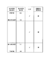
メインコントローラ35は、角度センサ40の出力信号よりバケット13の高さ位置を算出する。本実施形態において、バケット13の高さ位置とは、アーム11とバケット13とを連結する連結ピン12の高さ位置をいい、既知の値である連結ピン12の旋回半径と角度センサ39の出力値とから算出することができる。また、メインコントローラ35には、図3に示すように、バケット13の上下動方向に関して、可動範囲の下限位置H0及び上限位置H3と、下限位置H0よりも上方の第1の高さ位置H1と、上限位置H3よりも下方で第1の高さ位置H1よりも上方の第2の高さ位置H2とが記憶されると共に、バケット13の高さ位置に応じた制御弁32の自動切換を許容するか否かを選択するフラグが記憶される。なお、バケット13の下限位置H0はバケット13の外面が地面と接する位置であり、上限位置H3はホイールローダ1の車格(サイズ)によって定まる。また、第1及び第2の高さ位置H1,H2は、オペレータの好みに基づくものであり、走行時に経験的に上昇させるバケット13の高さ位置が基準となる。
図3の例では、バケット13の高さ位置Hが、H0≦H≦H1の範囲にある場合、H1<H<H2の範囲にある場合、及びH2≦H≦H3の範囲にある場合の全てについて、制御弁32の自動切換を許容することを示すレ点が記憶されており、バケット13の全可動範囲について、バケット13の高さ位置Hに応じた制御弁32の自動切換が行われる。即ち、本例にあっては、バケット13の高さ位置Hが、H0≦H≦H1の範囲にある場合及びH2≦H≦H3の範囲にある場合において、制御弁32が閉状態に切り換えられ、H1<H<H2の範囲にある場合において、制御弁32が開状態に切り換えられる。これにより、掘削作業時及び積み込み作業時においては、バケット13の動揺を防止することができるので、これらの作業を違和感無く行うことができて、オペレータの違和感及び不安感を解消することができる。これに対して、走行時には、液圧アキュムレータ31のダンパ効果によって前部車体5に作用するバケット13の重力変動が緩和されるので、ホイールローダ1の走行安定性を高めることができる。このメインコントローラ35の動作については、後に図4を用いてより詳細に説明する。
油圧回路34については、以下のように構成される。即ち、図2に示すように、リフトシリンダ16のロッド側室16aは、制御弁32を介して作動油タンク43に接続されており、リフトシリンダ16のボトム側室16bは、制御弁32を介して液圧アキュムレータ31に接続されている。制御弁32は、パイロット作動弁であり、ライドコントロール用の電磁パイロット弁44からの油圧パイロット信号に応じて開閉される。制御弁32が開状態にあるとき、作動油はリフトシリンダ16のロッド側室16aと作動油タンク43との間、及び、リフトシリンダ16のボトム側室16bと液圧アキュムレータ31と間が流通可能となり、バケット13の上下動にダンパ効果を付与することができる。これに対して、制御弁32が閉状態にあるとき、作動油はリフトシリンダ16のロッド側室16aと作動油タンク43との間、及び、リフトシリンダ16のボトム側室16bと液圧アキュムレータ31と間で流通不能となり、バケット13の重量がリフトシリンダ16を介して直接的に前部車体5に作用する。
電磁パイロット弁44は、メインコントローラ35から出力される切換信号により切換操作される。即ち、メインコントローラ35から制御弁32を開状態に切り換える信号が出力されると、電磁パイロット弁44は、パイロットポンプ45から吐出されるパイロット圧を制御弁32のパイロットポートに導く油路を開き、制御弁32を開状態に切り換える。これに対して、メインコントローラ35から制御弁32を閉状態に切り換える信号が出力されると、電磁パイロット弁44は、パイロット圧を作動油タンク43に落とす油路を開き、内蔵された戻しばねの弾性力によって制御弁32を閉状態に切り換える。
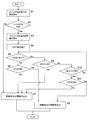
以下、図4を用いて、実施形態に係る作業車両の動作について説明する。エンジン36を始動(スタート)すると、メインコントローラ35はライドコントロールスイッチ39の出力信号を読み取り(ステップS1)、ライドコントロールスイッチ39の出力信号がON信号であるか否かを判定する(ステップS2)。ステップS2でライドコントロールスイッチ39の出力信号はOFF信号であると判定した場合には、ステップS7に移行して、システムを終了(エンド)する。
ステップS2で、ライドコントロールスイッチ39の出力信号はON信号であると判定した場合には、メインコントローラ35にて算出されたバケット13の高さ位置の読み取り(ステップS3)と、メインコントローラ35に記憶されたフラグの読み取り(ステップS4)とを行い、しかる後に、読み取られたバケット13の高さ位置HがH0≦H≦H1の範囲にあるか否かの判定(ステップS5)と、H0≦H≦H1の範囲についてオペレータにより制御弁32の自動切換が許容されているか否かの判定(ステップS6)をこの順に行う。ステップS5でバケット13の高さ位置HがH0≦H≦H1の範囲にあると判定され、ステップS6でH0≦H≦H1の範囲について制御弁32の自動切換が許容されていると判定した場合には、ステップS8に移行して、電磁パイロット弁44に制御弁32を閉状態に切り換える信号を出力する。なお、ステップS6でH0≦H≦H1の範囲について制御弁32の自動切換が許容されていないと判定した場合には、ステップS7に移行して、電磁パイロット弁44に制御弁32を開状態に切り換える信号を出力する。
ステップS5で、バケット13の高さ位置HがH0≦H≦H1の範囲にないと判定した場合は、ステップS9に移行して、バケット13の高さ位置HがH1<H<H2の範囲にあるか否かの判定を行う。ステップS9でバケット13の高さ位置HがH1<H<H2の範囲にあると判定した場合には、ステップS7に移行して、電磁パイロット弁44に制御弁32を開状態に切り換える信号を出力する。
さらに、ステップS9で、バケット13の高さ位置HがH1<H<H2の範囲にないと判定した場合は、バケット13の高さ位置HがH2≦H≦H3の範囲にあるか否かの判定(ステップS10)と、H2≦H≦H3の範囲についてオペレータにより制御弁32の自動切換が許容されているか否かの判定(ステップS11)とをこの順に行う。ステップS10でバケット13の高さ位置HがH2≦H≦H3の範囲にあると判定され、ステップS11でH2≦H≦H3の範囲について制御弁32の自動切換が許容されていると判定した場合、メインコントローラ35は電磁パイロット弁44に制御弁32を閉状態に切り換える信号を出力する。なお、ステップS10でH2≦H≦H3の範囲について制御弁32の自動切換が許容されていないと判定した場合には、ステップS7に移行して、電磁パイロット弁44に制御弁32を開状態に切り換える信号を出力する。
このように、本実施形態に係る走行振動抑制装置を備えた作業車両は、バケット13が掘削作業や積み込み作業を行う際の高さ位置にあるときには、制御弁32を閉状態に切り換えて、リフトシリンダ16と液圧アキュムレータ31との間の作動油の流通を遮断するので、バケット13の動揺を防止し作業を違和感無く行うことができ、オペレータの違和感や不安感を取り除くことができる。また、バケット13が走行時の高さ位置にあるときには、制御弁32を開状態に切り換えて、リフトシリンダ16と液圧アキュムレータ31との間で作動油を流通させるので、リフトシリンダ16のボトム圧変動を液圧アキュムレータ31のダンパ効果によって緩和することができ、ホイールローダ1の走行安定性を高めることができる。
本発明は、ホイールローダ等の作業車両における操作性及び走行安定性の改善に利用できる。
1 ホイールローダ
2 キャブ
3 後部車体
4,10,12,14,15,17,20,21 連結ピン
5 前部車体
6 後輪
7 前輪
8 フロント作業機
9 走行振動抑制装置
11 アーム
13 バケット(作業具)
16 リフトシリンダ
16a ロッド側室
16b ボトム側室
18 ベルクランク
19 リンク部材
22 バケット傾斜シリンダ
31 液圧アキュムレータ
32 制御弁
33 ライドコントロール部
34 油圧回路
35 メインコントローラ
36 エンジン
37 トランスミッション
38 エンジンコントローラ
39 ライドコントロールスイッチ
40 角度センサ
41 モニタユニット
42 インジケータ
43 作動油タンク
44 電磁パイロット弁
45 パイロットポンプ
Claims (2)
- 作業具を所定の可動範囲内で上下動するリフトシリンダと、制御弁を介して前記リフトシリンダに接続された液圧アキュムレータと、前記制御弁を開閉するライドコントロール部とを備えた作業車両において、
前記ライドコントロール部は、前記作業具の高さ位置に応じた検出信号を出力するセンサと、前記検出信号に応じた前記制御弁の切換信号を出力するコントローラとを有し、
前記コントローラは、前記作業具の高さ位置が前記可動範囲の下限位置からその上方に設定された第1の高さ位置の間にあると判定したとき、及び前記可動範囲の上限位置からその下方の前記第1の高さ位置よりも上方に設定された第2の高さ位置にあると判定したときには、前記制御弁を閉状態に切り換える切換信号を出力し、前記作業具の高さ位置が前記第1の高さ位置を超え、かつ前記第2の高さ位置未満であると判定したときには、前記制御弁を開状態に切り換える切換信号を出力することを特徴とする走行振動抑制装置を備えた作業車両。 - 前記コントローラは、前記可動範囲の下限位置から前記第1の高さ位置までの間、前記第1の高さ位置から前記第2の高さ位置までの間、及び前記第2の高さ位置から前記可動範囲の上限位置までの間について、前記検出信号に応じた前記切換信号の出力を可能にするフラグ又は不可能にするフラグの記憶領域を有しており、当該記憶領域に前記検出信号に応じた前記切換信号の出力を可能にするフラグが記憶された前記作業機の高さ位置についてのみ、前記検出信号に応じた前記切換信号の出力を行うことを特徴とする請求項1に記載の走行振動抑制装置を備えた作業車両。
Applications Claiming Priority (2)
| Application Number | Priority Date | Filing Date | Title |
|---|---|---|---|
| JP2011-056636 | 2011-03-15 | ||
| JP2011056636A JP2012193509A (ja) | 2011-03-15 | 2011-03-15 | 走行振動抑制装置を備えた作業車両 |
Publications (1)
| Publication Number | Publication Date |
|---|---|
| WO2012124657A1 true WO2012124657A1 (ja) | 2012-09-20 |
Family
ID=46830726
Family Applications (1)
| Application Number | Title | Priority Date | Filing Date |
|---|---|---|---|
| PCT/JP2012/056295 Ceased WO2012124657A1 (ja) | 2011-03-15 | 2012-03-12 | 走行振動抑制装置を備えた作業車両 |
Country Status (2)
| Country | Link |
|---|---|
| JP (1) | JP2012193509A (ja) |
| WO (1) | WO2012124657A1 (ja) |
Families Citing this family (2)
| Publication number | Priority date | Publication date | Assignee | Title |
|---|---|---|---|---|
| CN107150565A (zh) * | 2017-06-15 | 2017-09-12 | 湖南三快而居住宅工业有限公司 | 一种油气悬挂装置、控制方法及运材半挂车 |
| JP7034010B2 (ja) * | 2018-06-04 | 2022-03-11 | 日立建機株式会社 | ホイール式作業機械 |
Citations (2)
| Publication number | Priority date | Publication date | Assignee | Title |
|---|---|---|---|---|
| JPS6442358U (ja) * | 1987-09-07 | 1989-03-14 | ||
| JP3016273U (ja) * | 1995-03-28 | 1995-09-26 | 古河機械金属株式会社 | ホイールローダの走行安定機構の自動入切装置 |
-
2011
- 2011-03-15 JP JP2011056636A patent/JP2012193509A/ja not_active Withdrawn
-
2012
- 2012-03-12 WO PCT/JP2012/056295 patent/WO2012124657A1/ja not_active Ceased
Patent Citations (2)
| Publication number | Priority date | Publication date | Assignee | Title |
|---|---|---|---|---|
| JPS6442358U (ja) * | 1987-09-07 | 1989-03-14 | ||
| JP3016273U (ja) * | 1995-03-28 | 1995-09-26 | 古河機械金属株式会社 | ホイールローダの走行安定機構の自動入切装置 |
Also Published As
| Publication number | Publication date |
|---|---|
| JP2012193509A (ja) | 2012-10-11 |
Similar Documents
| Publication | Publication Date | Title |
|---|---|---|
| US20130073151A1 (en) | Damper operation control device and damper operation control method for working vehicle | |
| JP5707313B2 (ja) | 作業車両 | |
| JP5277449B2 (ja) | 作業車両並びに作業車両の制御方法および制御装置 | |
| CN111655938B (zh) | 挖土机 | |
| JP7557488B2 (ja) | ショベル | |
| KR101669452B1 (ko) | 포크 리프트의 유압 제어 장치 | |
| JP2010265639A (ja) | 作業車両 | |
| JP5005016B2 (ja) | 作業車両の走行振動抑制装置 | |
| RU2008129646A (ru) | Рабочая машина | |
| WO2012124657A1 (ja) | 走行振動抑制装置を備えた作業車両 | |
| EP3095746B1 (en) | Hydraulic control device of a forklift truck | |
| JP2005155230A (ja) | 車輪式建設機械の走行振動抑制油圧回路 | |
| JP5690620B2 (ja) | 走行振動抑制装置を備えた作業車両 | |
| JP2012013156A (ja) | 作業機械 | |
| US12385224B2 (en) | Wheeled construction machine | |
| JP4131497B2 (ja) | 車輪式建設機械の走行振動抑制油圧回路 | |
| JP6678141B2 (ja) | 油圧ショベル | |
| JP5315443B2 (ja) | ホイールローダ | |
| JP2607678Y2 (ja) | 作業機の振動抑制装置 | |
| JPH0714203U (ja) | 作業機の振動抑制装置 | |
| JP2006077451A (ja) | 作業車両の作業機用油圧ポンプの容量制御方法及び容量制御装置 | |
| JP3000197U (ja) | 建設車両の走行安定機構における作業装置降下抑制装置 | |
| JPH1181391A (ja) | 作業機の制振制御装置 | |
| US12392111B2 (en) | Work machine | |
| JP4966244B2 (ja) | 作業車のサスペンション構造 |
Legal Events
| Date | Code | Title | Description |
|---|---|---|---|
| 121 | Ep: the epo has been informed by wipo that ep was designated in this application |
Ref document number: 12758373 Country of ref document: EP Kind code of ref document: A1 |
|
| NENP | Non-entry into the national phase |
Ref country code: DE |
|
| 122 | Ep: pct application non-entry in european phase |
Ref document number: 12758373 Country of ref document: EP Kind code of ref document: A1 |