WO2012127523A1 - Appareil de culture pour la visualisation microscopique et son procédé d'utilisation - Google Patents
Appareil de culture pour la visualisation microscopique et son procédé d'utilisation Download PDFInfo
- Publication number
- WO2012127523A1 WO2012127523A1 PCT/JP2011/001660 JP2011001660W WO2012127523A1 WO 2012127523 A1 WO2012127523 A1 WO 2012127523A1 JP 2011001660 W JP2011001660 W JP 2011001660W WO 2012127523 A1 WO2012127523 A1 WO 2012127523A1
- Authority
- WO
- WIPO (PCT)
- Prior art keywords
- culture apparatus
- temperature
- container
- lid
- culture
- Prior art date
- Legal status (The legal status is an assumption and is not a legal conclusion. Google has not performed a legal analysis and makes no representation as to the accuracy of the status listed.)
- Ceased
Links
Images


Classifications
-
- C—CHEMISTRY; METALLURGY
- C12—BIOCHEMISTRY; BEER; SPIRITS; WINE; VINEGAR; MICROBIOLOGY; ENZYMOLOGY; MUTATION OR GENETIC ENGINEERING
- C12M—APPARATUS FOR ENZYMOLOGY OR MICROBIOLOGY; APPARATUS FOR CULTURING MICROORGANISMS FOR PRODUCING BIOMASS, FOR GROWING CELLS OR FOR OBTAINING FERMENTATION OR METABOLIC PRODUCTS, i.e. BIOREACTORS OR FERMENTERS
- C12M1/00—Apparatus for enzymology or microbiology
- C12M1/34—Measuring or testing with condition measuring or sensing means, e.g. colony counters
-
- C—CHEMISTRY; METALLURGY
- C12—BIOCHEMISTRY; BEER; SPIRITS; WINE; VINEGAR; MICROBIOLOGY; ENZYMOLOGY; MUTATION OR GENETIC ENGINEERING
- C12M—APPARATUS FOR ENZYMOLOGY OR MICROBIOLOGY; APPARATUS FOR CULTURING MICROORGANISMS FOR PRODUCING BIOMASS, FOR GROWING CELLS OR FOR OBTAINING FERMENTATION OR METABOLIC PRODUCTS, i.e. BIOREACTORS OR FERMENTERS
- C12M1/00—Apparatus for enzymology or microbiology
- C12M1/36—Apparatus for enzymology or microbiology including condition or time responsive control, e.g. automatically controlled fermentors
- C12M1/38—Temperature-responsive control
-
- C—CHEMISTRY; METALLURGY
- C12—BIOCHEMISTRY; BEER; SPIRITS; WINE; VINEGAR; MICROBIOLOGY; ENZYMOLOGY; MUTATION OR GENETIC ENGINEERING
- C12M—APPARATUS FOR ENZYMOLOGY OR MICROBIOLOGY; APPARATUS FOR CULTURING MICROORGANISMS FOR PRODUCING BIOMASS, FOR GROWING CELLS OR FOR OBTAINING FERMENTATION OR METABOLIC PRODUCTS, i.e. BIOREACTORS OR FERMENTERS
- C12M23/00—Constructional details, e.g. recesses, hinges
- C12M23/02—Form or structure of the vessel
- C12M23/12—Well or multiwell plates
-
- C—CHEMISTRY; METALLURGY
- C12—BIOCHEMISTRY; BEER; SPIRITS; WINE; VINEGAR; MICROBIOLOGY; ENZYMOLOGY; MUTATION OR GENETIC ENGINEERING
- C12M—APPARATUS FOR ENZYMOLOGY OR MICROBIOLOGY; APPARATUS FOR CULTURING MICROORGANISMS FOR PRODUCING BIOMASS, FOR GROWING CELLS OR FOR OBTAINING FERMENTATION OR METABOLIC PRODUCTS, i.e. BIOREACTORS OR FERMENTERS
- C12M23/00—Constructional details, e.g. recesses, hinges
- C12M23/22—Transparent or translucent parts
-
- C—CHEMISTRY; METALLURGY
- C12—BIOCHEMISTRY; BEER; SPIRITS; WINE; VINEGAR; MICROBIOLOGY; ENZYMOLOGY; MUTATION OR GENETIC ENGINEERING
- C12M—APPARATUS FOR ENZYMOLOGY OR MICROBIOLOGY; APPARATUS FOR CULTURING MICROORGANISMS FOR PRODUCING BIOMASS, FOR GROWING CELLS OR FOR OBTAINING FERMENTATION OR METABOLIC PRODUCTS, i.e. BIOREACTORS OR FERMENTERS
- C12M23/00—Constructional details, e.g. recesses, hinges
- C12M23/38—Caps; Covers; Plugs; Pouring means
-
- C—CHEMISTRY; METALLURGY
- C12—BIOCHEMISTRY; BEER; SPIRITS; WINE; VINEGAR; MICROBIOLOGY; ENZYMOLOGY; MUTATION OR GENETIC ENGINEERING
- C12M—APPARATUS FOR ENZYMOLOGY OR MICROBIOLOGY; APPARATUS FOR CULTURING MICROORGANISMS FOR PRODUCING BIOMASS, FOR GROWING CELLS OR FOR OBTAINING FERMENTATION OR METABOLIC PRODUCTS, i.e. BIOREACTORS OR FERMENTERS
- C12M23/00—Constructional details, e.g. recesses, hinges
- C12M23/48—Holding appliances; Racks; Supports
-
- C—CHEMISTRY; METALLURGY
- C12—BIOCHEMISTRY; BEER; SPIRITS; WINE; VINEGAR; MICROBIOLOGY; ENZYMOLOGY; MUTATION OR GENETIC ENGINEERING
- C12M—APPARATUS FOR ENZYMOLOGY OR MICROBIOLOGY; APPARATUS FOR CULTURING MICROORGANISMS FOR PRODUCING BIOMASS, FOR GROWING CELLS OR FOR OBTAINING FERMENTATION OR METABOLIC PRODUCTS, i.e. BIOREACTORS OR FERMENTERS
- C12M3/00—Tissue, human, animal or plant cell, or virus culture apparatus
-
- C—CHEMISTRY; METALLURGY
- C12—BIOCHEMISTRY; BEER; SPIRITS; WINE; VINEGAR; MICROBIOLOGY; ENZYMOLOGY; MUTATION OR GENETIC ENGINEERING
- C12M—APPARATUS FOR ENZYMOLOGY OR MICROBIOLOGY; APPARATUS FOR CULTURING MICROORGANISMS FOR PRODUCING BIOMASS, FOR GROWING CELLS OR FOR OBTAINING FERMENTATION OR METABOLIC PRODUCTS, i.e. BIOREACTORS OR FERMENTERS
- C12M41/00—Means for regulation, monitoring, measurement or control, e.g. flow regulation
- C12M41/12—Means for regulation, monitoring, measurement or control, e.g. flow regulation of temperature
- C12M41/14—Incubators; Climatic chambers
-
- C—CHEMISTRY; METALLURGY
- C12—BIOCHEMISTRY; BEER; SPIRITS; WINE; VINEGAR; MICROBIOLOGY; ENZYMOLOGY; MUTATION OR GENETIC ENGINEERING
- C12M—APPARATUS FOR ENZYMOLOGY OR MICROBIOLOGY; APPARATUS FOR CULTURING MICROORGANISMS FOR PRODUCING BIOMASS, FOR GROWING CELLS OR FOR OBTAINING FERMENTATION OR METABOLIC PRODUCTS, i.e. BIOREACTORS OR FERMENTERS
- C12M41/00—Means for regulation, monitoring, measurement or control, e.g. flow regulation
- C12M41/30—Means for regulation, monitoring, measurement or control, e.g. flow regulation of concentration
- C12M41/36—Means for regulation, monitoring, measurement or control, e.g. flow regulation of concentration of biomass, e.g. colony counters or by turbidity measurements
-
- G—PHYSICS
- G02—OPTICS
- G02B—OPTICAL ELEMENTS, SYSTEMS OR APPARATUS
- G02B21/00—Microscopes
- G02B21/24—Base structure
- G02B21/30—Base structure with heating device
-
- G—PHYSICS
- G02—OPTICS
- G02B—OPTICAL ELEMENTS, SYSTEMS OR APPARATUS
- G02B21/00—Microscopes
- G02B21/34—Microscope slides, e.g. mounting specimens on microscope slides
-
- G—PHYSICS
- G02—OPTICS
- G02B—OPTICAL ELEMENTS, SYSTEMS OR APPARATUS
- G02B7/00—Mountings, adjusting means, or light-tight connections, for optical elements
- G02B7/008—Mountings, adjusting means, or light-tight connections, for optical elements with means for compensating for changes in temperature or for controlling the temperature; thermal stabilisation
Definitions
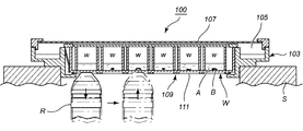
- the present invention relates to a culture apparatus for microscopic observation suitable for observing a sample such as a cell.
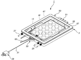
- This culture apparatus for microscopic observation 100 includes a housing unit 103 and a lid body 107 that closes the upper surface side opening.
- a water tank 105 is provided along the inner edge side in the storage unit 103, and the inside is a storage space.
- a container in which a culture solution A and a sample B such as a cell are placed in the storage space, for example, In a state in which the well plate W is accommodated, it is installed on the microscope stage S and used.
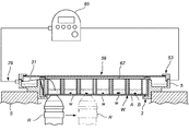
- the temperature needs to be kept constant, for example, about 37 ° C. Therefore, conventionally, a heating plate 109 formed of a thin plate of aluminum having high heat conductivity is placed on the lower surface side opening of the storage unit 103, and a well plate W is placed thereon to heat the culture medium A from below.
- a heating plate 109 formed of a thin plate of aluminum having high heat conductivity is placed on the lower surface side opening of the storage unit 103, and a well plate W is placed thereon to heat the culture medium A from below.
- the heating plate 109 is used as a translucent part by making a hole 111 in a portion where each well w is opposed so as not to hinder microscopic observation.
- an inverted microscope when used, there is a tendency to bring the objective lens R closer to the lower surface of the housing unit 103 than before, but as described above.
- the warm plate 109 when the microscope stage S is moved two-dimensionally in the XY direction to change the observation target from one well w to the adjacent well w, as shown by the arrows, Once the objective lens R is retracted, an operation of moving the microscope stage S and then bringing the objective lens R back again is necessary, and the programming is complicated even if the objective lens R is automatically operated.
- the objective lens R is used as an oil immersion or water immersion lens by filling between the lower surface of the bare container and the objective lens R with oil or water.
- the liquid ball easily collapses.
- the heating plate 109 Since there is a difference in the distance to each well w, a temperature gradient is generated between the wells w. Further, even in one well w, a temperature gradient is generated between the edge side and the inner side.
- the present invention provides a culture apparatus for microscopic observation that enables efficient execution of microscopic observation at a high magnification while maintaining a sample of cells or the like in a culture solution at a constant temperature, and use of an example thereof Its purpose is to provide a method.
- the present invention solves the above-mentioned problems, and the invention according to claim 1 includes a storage unit that stores a container containing a culture solution and a sample, and a lid that closes an upper surface side opening of the storage unit.
- a microscopic observation culture apparatus used for microscopic observation of the sample installed on a stage of a microscope, a transparent planar top heater provided in a portion corresponding to the observation range of the lid, and a fine wire
- a temperature detection means for directly measuring the temperature of the culture solution supplied into the container contained in the container and entering the inside of the storage unit, from the temperature detection means
- a culture apparatus for microscope observation characterized in that the temperature of the transparent planar top heater is controlled by a feedback method based on temperature information.
- the invention of claim 2 is the culture apparatus for microscopic observation described in claim 1, further comprising introduction means for introducing the detection portion of the temperature detection means into the accommodation unit in a freely adjustable length.
- a third aspect of the invention is the microscope observation culture apparatus according to the first or second aspect of the invention, in which a lid for a dedicated container is provided, and the detection unit of the temperature detection means is the lid.
- a culture apparatus for microscopic observation wherein the culture apparatus is introduced into a container through introduction means attached to a body.
- the invention according to claim 4 is the culture apparatus for microscope observation according to claim 3, wherein the lid of the container is formed of transparent glass.
- the invention of claim 5 is the method of using the culture apparatus for microscopic observation according to any one of claims 1 to 4, wherein a container divided by a plurality of sections, or a plurality of containers is provided. Use characterized by being housed in a unit and using one of the sections or containers to detect the temperature of the temperature detection means and using the remaining sections or containers for microscopic observation. Is the method.
- the culture device for microscopic observation of the present invention it is possible to efficiently perform microscopic observation at a high magnification while maintaining a sample such as a cell in a culture solution at a constant temperature.
- FIG. 2 is a partially enlarged perspective view on the side of a storage unit related to temperature control means of the microscope observation culture apparatus of FIG. 1.
- FIG. 2 is a partially enlarged perspective view of a container side related to temperature control means of the microscope observation culture apparatus of FIG. 1. It is operation
- movement explanatory drawing of an objective lens when the conventional culture apparatus for microscope observation is used.
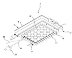
- FIG. 1 indicates a main body portion formed in a substantially rectangular frame shape, and an upper surface side opening 7 and a lower surface side opening 9 are formed in the main body portion 5, respectively.
- An inner flange 11 is formed on the lower surface side opening 9 side, and the lower surface side opening 9 is smaller than the upper surface side opening 7.
- the side surface of the adapter 13 is fitted and fixed to the edge of the lower surface side opening 9 of the main body 5.
- the adapter 13 is also formed in a substantially rectangular frame shape, and an inner flange 17 is formed on the lower end side opening 15 side.
- Reference numeral 19 denotes a presser spring, and the base end of the presser spring 19 is connected to each of four locations on the upper end surface of the adapter 13 so as to be rotatable within the adapter 13.
- the adapter 13 is for the well plate W. When the well plate W is detachably fitted, the adapter 13 is stably fixed to the adapter 13 by the elastic force of the presser spring 19 described above.
- the lower end side of the adapter 13 protrudes downward from the accommodation unit 3, and a step portion 21 is formed between the adapter 13 and the accommodation unit 3.
- a concave space defined between the inner surface of the main body 5, the outer surface of the adapter 13, and the upper surface of the inner flange 11 of the main body 5 serves as the water tank 23.
- a water supply hose 25 and a gas supply hose 27 are attached to the main body 5, and the tips of the water supply hose 27 enter the water tank 23, and the tip of the gas supply hose 27 extends to the vicinity of the bottom surface.
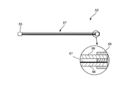
- a detector holder 33 is provided as an in-container introduction unit for the thin-line thermocouple detector 31 of the temperature detector 29.
- the base block 35 of the detection unit holder 33 is fixed to the outer surface of the main body unit 5, and the base block 35 corresponds to the pair of screw holes 37 and 37 and the detection unit 31.
- a shallow groove 39 is formed.
- the groove 39 communicates with a groove 41 formed on the upper end surface of the main body 5, and the grooves 39 and 41 serve as an introduction path into the main body 5 of the detection unit 31.
- a presser block 43 is provided corresponding to the base block 35, and a pair of holes 45, 45 are also formed in the presser block 43 corresponding to the pair of screw holes 37, 37 on the base block 35 side.
- a suitable portion of the detection unit 31 is inserted from the groove 39 of the base block 35 to the groove 41 of the main body 5, and the presser block 43 is aligned from above so that the lower surface side protrusion fits into the groove 39 of the base block 35.
- the detection unit 31 is fixed in a state of being introduced into the main body unit 5.
- the detection unit 31 can adjust the length of introduction into the main body unit 5 by changing the insertion positions in the grooves 39 and 41, and the predetermined well of the well plate W can be adjusted. It is possible to enter a sufficient length so as to reach w.
- the main body 5 is also provided with a mounting holder 51 for a pair of perfusion hoses so that perfusion culture is possible.
- a lid 53 is provided so as to close the upper end side opening 7 relative to the housing unit 3 having the above structure.
- the lid 53 has a substantially rectangular shape
- the frame 55 holds a transparent transparent portion 57 having a rectangular shape.
- Two transparent glass plates 59 are arranged with a gap in the light transmitting portion 57, and a transparent conductive film 61 is formed on the upper surface of the lower transparent glass plate 59.
- the transparent conductive film 61 is caused to generate heat by being energized through the electric cord 63, and has a function as a transparent planar top heater. Since an air layer is interposed between the two transparent glass plates 59, 59, a heat insulating effect can be expected.
- the electric cord 63 on the lid 53 side and the temperature detection means 29 are both connected to the controller 65, and the controller 65 is transparently conductive by a feedback method based on the temperature information from the temperature detection means 29 and the target temperature. The amount of current supplied to the film 61 is adjusted.
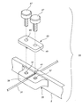
- the well plate W to be attached to the adapter 13 may or may not have a lid, but the well plate W to be attached in this embodiment has a lid 67 and is a detection unit of the temperature detection means 29.
- the lid 67 is provided with an in-well plate introducing means.
- the lid 67 is made of transparent glass in order to suppress fluorescent color development.
- the lid 67 is box-shaped and is fitted into a stepped portion formed on the outer surface of the well plate W so as to close the upper surface opening of the well plate W. Yes.
- a small rectangular hole 69 is formed in the upper wall portion of the lid 67 on the side wall portion side, and a pair of screw holes 71 and 71 are formed in the upper end surface of the exposed side wall portion. In addition, a shallow groove (not shown) corresponding to the detection unit 31 is formed between them.
- a rectangular holding plate 73 having a size that fits into the rectangular hole 69 is provided. The holding plate 73 also has a pair of screw holes 75 and 75 corresponding to the pair of screw holes 71 and 71. .
- the detecting unit 31 is inserted into the groove, the presser plate 73 is fitted into the rectangular hole 69 from above, and the presser screw 77 is tightened into the screw holes 75 and 71 to be introduced into the well plate W of the detecting unit 31. It is fixed in the state that was done.
- the detection unit 31 can be bent, and after extending to a predetermined well w in the well plate W, it can be bent and lowered to the vicinity of the bottom surface of the well w.
- An adapter 13 is attached to the main body 5 of the housing unit 3 in advance.
- the adapter 13 is fitted with a dummy well plate W (closed with a lid 67) and closed with a lid 53 to define a culture space, and then carbon dioxide (CO 2 ) is supplied from the gas supply hose 27.
- CO 2 carbon dioxide
- the transparent conductive film 61 of the transparent planar top heater is energized through the electric cord 63 to generate heat.
- a heater is also installed on the bottom side of the water tank 23. By heating the heater, water in the water tank 23 is evaporated to bring the culture space to a desired humidity.
- the gas supply hose 27, the water supply hose 25, and the heater described above are also under the control of the controller 65, and the culture space is maintained constant.
- the accommodation unit 3 is installed on the microscope stage S.
- the step portion 21 on the lower surface side of the main body portion 5 of the housing unit 3 is placed on the edge of the hole of the microscope stage S.
- a well plate W for microscopic observation is prepared.
- the culture medium A and the sample B are placed in each well w in advance, but one well w on the outer edge side of the well plate W is dedicated to temperature detection, and only the culture medium A is placed.
- the tip exposed from the protective tube of the detection unit 31 of the temperature detection means 29 is inserted into the well w dedicated to temperature detection, lowered to the vicinity of the bottom surface and immersed in the culture medium A, and then the lid 67.
- the opening on the upper surface side of the well plate W is closed, and the detection unit 31 is fixed by the introduction means in the well plate.
- the lid 53 of the storage unit 3 is opened, the dummy well plate W is taken out, the well plate W for microscopic observation is fitted, and the detection unit After fixing the detection unit 31 of the temperature detection means 29 via the holder 33, the storage unit 3 is closed again with the lid 53.
- the culture solution containing the sample put in each well w of the well plate W in the culture space is maintained in an environment such as a predetermined humidity and temperature suitable for culture and enters an observable mode.
- the sample B that has entered the plurality of wells w is observed in parallel while the microscope stage S is moved.
- the portion where each well w is arranged is bare on the lower side over the entire surface, and the wells w are bare and are flush with each other. Therefore, the microscope stage S can be moved in the XY directions while the objective lens R is in the state closest to the well w for observation.
- the transparent planar top heaters are opposed to each well w at an equal distance, the culture solution A and sample B contained in any well w are uniformly heated. Furthermore, since the transparent planar top heater is heated based on the direct temperature information of the culture medium A, it is possible to sequentially follow even minute temperature fluctuations without delay.
- the entered sample B can always be maintained at a target heating temperature with high accuracy.
- a container such as a well plate is not a dedicated one for the culture apparatus for microscopic observation of the present invention, but may be used in combination with an optional one. If the container is to be closed with a lid, the lid If the one described in the above embodiment is used, the detection part of the temperature detection means can be successfully introduced into the container.
- the container is not limited to a well plate but may be a dish. In that case, for example, two dishes can be used, and one dish can be used exclusively for temperature detection.
- preparing a dedicated one for temperature detection is a case where it becomes an obstacle at the time of observation work or if you are concerned about contamination from the detection unit, but the detection unit can be sterilized, If you do not care about them, you can put the sample in the well where the detector is inserted and use it for microscopic observation.
- the culture device for microscopic observation of the present invention can be used as an accessory of a microscope.
- Lid body 55 ... Frame body 57 ... Translucent part 59 ... Transparent glass plate 61 ... Transparent conductive film 63 ... Electric cord 65 ... Controller 67: Lid (well plate) 69 ... Rectangular hole 71 ... Screw hole 73 ... Presser plate 75 ... Screw hole 77 ... Presser screw W ... Well plate w ... Well A ... Culture medium B ... Sample S ... Microscope stage R ... Objective lens
Landscapes
- Chemical & Material Sciences (AREA)
- Health & Medical Sciences (AREA)
- Life Sciences & Earth Sciences (AREA)
- Engineering & Computer Science (AREA)
- Bioinformatics & Cheminformatics (AREA)
- Wood Science & Technology (AREA)
- Zoology (AREA)
- Organic Chemistry (AREA)
- Biotechnology (AREA)
- Biomedical Technology (AREA)
- General Health & Medical Sciences (AREA)
- Sustainable Development (AREA)
- Microbiology (AREA)
- Biochemistry (AREA)
- General Engineering & Computer Science (AREA)
- Genetics & Genomics (AREA)
- Physics & Mathematics (AREA)
- Analytical Chemistry (AREA)
- Clinical Laboratory Science (AREA)
- General Physics & Mathematics (AREA)
- Optics & Photonics (AREA)
- Thermal Sciences (AREA)
- Medicinal Chemistry (AREA)
- Cell Biology (AREA)
- Virology (AREA)
- Apparatus Associated With Microorganisms And Enzymes (AREA)
- Microscoopes, Condenser (AREA)
Abstract
Priority Applications (8)
| Application Number | Priority Date | Filing Date | Title |
|---|---|---|---|
| AU2011363361A AU2011363361B2 (en) | 2011-03-22 | 2011-03-22 | Culture Apparatus for Microscope Viewing and Method Therefor |
| CA2804568A CA2804568A1 (fr) | 2011-03-22 | 2011-03-22 | Appareil de culture pour la visualisation microscopique et son procede d'utilisation |
| KR1020137007209A KR101741650B1 (ko) | 2011-03-22 | 2011-03-22 | 현미경 관찰용 배양장치 및 그 사용 방법 |
| JP2013505611A JP5709976B2 (ja) | 2011-03-22 | 2011-03-22 | 顕微鏡観察用培養装置およびその使用方法 |
| US13/808,004 US8822204B2 (en) | 2011-03-22 | 2011-03-22 | Culture apparatus for microscope viewing and method therefor |
| PCT/JP2011/001660 WO2012127523A1 (fr) | 2011-03-22 | 2011-03-22 | Appareil de culture pour la visualisation microscopique et son procédé d'utilisation |
| EP11861878.4A EP2690167B1 (fr) | 2011-03-22 | 2011-03-22 | Appareil de culture pour la visualisation microscopique et son procédé d'utilisation |
| CN201180046154.9A CN103476919B (zh) | 2011-03-22 | 2011-03-22 | 显微镜观察用培养装置及其使用方法 |
Applications Claiming Priority (1)
| Application Number | Priority Date | Filing Date | Title |
|---|---|---|---|
| PCT/JP2011/001660 WO2012127523A1 (fr) | 2011-03-22 | 2011-03-22 | Appareil de culture pour la visualisation microscopique et son procédé d'utilisation |
Publications (1)
| Publication Number | Publication Date |
|---|---|
| WO2012127523A1 true WO2012127523A1 (fr) | 2012-09-27 |
Family
ID=46878730
Family Applications (1)
| Application Number | Title | Priority Date | Filing Date |
|---|---|---|---|
| PCT/JP2011/001660 Ceased WO2012127523A1 (fr) | 2011-03-22 | 2011-03-22 | Appareil de culture pour la visualisation microscopique et son procédé d'utilisation |
Country Status (8)
| Country | Link |
|---|---|
| US (1) | US8822204B2 (fr) |
| EP (1) | EP2690167B1 (fr) |
| JP (1) | JP5709976B2 (fr) |
| KR (1) | KR101741650B1 (fr) |
| CN (1) | CN103476919B (fr) |
| AU (1) | AU2011363361B2 (fr) |
| CA (1) | CA2804568A1 (fr) |
| WO (1) | WO2012127523A1 (fr) |
Cited By (8)
| Publication number | Priority date | Publication date | Assignee | Title |
|---|---|---|---|---|
| JP2016021969A (ja) * | 2014-07-24 | 2016-02-08 | 国立大学法人 東京大学 | 細胞培養装置およびこれを備える細胞培養試験観察システム |
| JP2017520242A (ja) * | 2014-06-06 | 2017-07-27 | ジェンザイム・コーポレーション | 灌流培養方法およびその使用 |
| CN110709501A (zh) * | 2017-05-04 | 2020-01-17 | 苏黎世大学 | 细胞培养装置 |
| JP2021513344A (ja) * | 2018-02-09 | 2021-05-27 | グローバル・ライフ・サイエンシズ・ソリューションズ・ユーエスエー・エルエルシー | バイオプロセッシングのための使い捨てキット |
| US11920119B2 (en) | 2018-02-09 | 2024-03-05 | Global Life Sciences Solutions Usa Llc | Systems and methods for bioprocessing |
| US11932842B2 (en) | 2018-02-09 | 2024-03-19 | Global Life Sciences Solutions Usa Llc | Bioprocessing apparatus |
| US12077743B2 (en) | 2018-02-09 | 2024-09-03 | Global Life Sciences Solutions Usa Llc | Apparatus for fluid line management in a bioprocessing system |
| US12252682B2 (en) | 2018-02-09 | 2025-03-18 | Global Life Sciences Solutions Usa Llc | System and method for fluid flow management in a bioprocessing system |
Families Citing this family (21)
| Publication number | Priority date | Publication date | Assignee | Title |
|---|---|---|---|---|
| JP5831867B2 (ja) * | 2011-03-30 | 2015-12-09 | 国立大学法人島根大学 | 物質相互作用をリアルタイムに可視化する技術 |
| CA2887135A1 (fr) * | 2012-10-08 | 2014-04-17 | University Of Virgina Patent Foundation D/B/A University Of Virginia Licensing & Ventures Group | Lecteur de plaque multi-puits miniaturise pour criblage phenotypique |
| US9315769B2 (en) | 2012-12-11 | 2016-04-19 | Billups-Rothenberg, Inc. | Incubator chamber |
| USD740947S1 (en) * | 2013-05-14 | 2015-10-13 | Life Technologies Corporation | Microscope stage-top incubator system |
| US20170002307A1 (en) * | 2014-03-10 | 2017-01-05 | SCREEN Holdings Co., Ltd. | Imaging Apparatus, Imaging System and Incubator |
| WO2016124505A1 (fr) * | 2015-02-05 | 2016-08-11 | General Electric Company | Système de bioréacteur pour culture cellulaire |
| GB2539275A (en) * | 2015-06-12 | 2016-12-14 | Planer Plc | Incubator |
| CN105068236A (zh) * | 2015-07-30 | 2015-11-18 | 苏州欧可罗电子科技有限公司 | 一种高效率加热式显微镜 |
| US10351812B2 (en) * | 2015-08-28 | 2019-07-16 | Axion Biosystems, Inc. | Device and system for creating and maintaining a localized environment for a cell culture plate |
| IL299626A (en) | 2015-10-01 | 2023-03-01 | Berkeley Lights Inc | Multi-well plate incubator |
| US20190352594A1 (en) * | 2016-11-10 | 2019-11-21 | Kataoka Corporation | Culture vessel housing apparatus |
| EP3548602B1 (fr) | 2016-12-01 | 2024-09-25 | Bruker Cellular Analysis, Inc. | Incubateur en plaque de puits |
| JP2018102228A (ja) * | 2016-12-27 | 2018-07-05 | オリンパス株式会社 | 観察装置 |
| JP2020531038A (ja) | 2017-08-31 | 2020-11-05 | フィリップ・モーリス・プロダクツ・ソシエテ・アノニム | インビトロ曝露のための細胞培養プレート、デバイスおよび方法 |
| EP3450940B1 (fr) | 2017-09-05 | 2023-06-07 | PeCon GmbH | Dispositif de mesure |
| EP3724315A1 (fr) * | 2017-12-15 | 2020-10-21 | Technische Universität Ilmenau | Agencement de microbioréacteur |
| US10889792B2 (en) | 2018-02-09 | 2021-01-12 | Global Life Sciences Solutions Usa Llc | Cell expansion vessel systems and methods |
| FR3111356B1 (fr) * | 2020-06-12 | 2022-07-01 | Commissariat Energie Atomique | Boîte de culture |
| EP4412761A1 (fr) * | 2021-10-07 | 2024-08-14 | CooperSurgical, Inc. | Incubateurs modulaires pour postes de travail configurables |
| CN114815214A (zh) * | 2022-05-18 | 2022-07-29 | 苏州博致医疗科技有限公司 | 一种基于压电驱动的三维运动台 |
| EP4393598A1 (fr) * | 2022-12-27 | 2024-07-03 | TECAN Trading AG | Plaque d'équilibrage de température pour un lecteur de microplaque et lecteur de microplaque doté d'une telle plaque d'équilibrage de température |
Citations (2)
| Publication number | Priority date | Publication date | Assignee | Title |
|---|---|---|---|---|
| JP2004141143A (ja) * | 2002-08-28 | 2004-05-20 | Tokai Hit:Kk | 顕微鏡観察用培養器 |
| JP2008259430A (ja) | 2007-04-10 | 2008-10-30 | Tokai Hit:Kk | 顕微鏡観察用培養器 |
Family Cites Families (7)
| Publication number | Priority date | Publication date | Assignee | Title |
|---|---|---|---|---|
| US4629862A (en) * | 1984-03-28 | 1986-12-16 | Olympus Optical Company Ltd. | Sample heater for use in microscopes |
| US6365367B1 (en) * | 1999-12-06 | 2002-04-02 | Cellomics, Inc. | Environmental chamber for the analysis of live cells |
| JP4321841B2 (ja) * | 2001-09-27 | 2009-08-26 | 株式会社東海ヒット | 顕微鏡観察用培養器 |
| US7623289B2 (en) * | 2004-07-22 | 2009-11-24 | Olympus Corporation | Observation apparatus having thermoregulation mechanism |
| JP4354446B2 (ja) * | 2005-10-13 | 2009-10-28 | 株式会社東海ヒット | 顕微鏡ステージ及び顕微鏡観察用ユニット |
| HU227211B1 (en) * | 2007-05-22 | 2010-11-29 | Miklos Csiszer | Incubator procedure for observing living cells with microscope |
| JP2009201509A (ja) * | 2008-02-01 | 2009-09-10 | Kunio Isono | 透明導電膜加工からなる培養容器とその製造方法 |
-
2011
- 2011-03-22 US US13/808,004 patent/US8822204B2/en active Active
- 2011-03-22 JP JP2013505611A patent/JP5709976B2/ja not_active Expired - Fee Related
- 2011-03-22 CA CA2804568A patent/CA2804568A1/fr not_active Abandoned
- 2011-03-22 EP EP11861878.4A patent/EP2690167B1/fr not_active Not-in-force
- 2011-03-22 AU AU2011363361A patent/AU2011363361B2/en not_active Ceased
- 2011-03-22 CN CN201180046154.9A patent/CN103476919B/zh not_active Expired - Fee Related
- 2011-03-22 WO PCT/JP2011/001660 patent/WO2012127523A1/fr not_active Ceased
- 2011-03-22 KR KR1020137007209A patent/KR101741650B1/ko not_active Expired - Fee Related
Patent Citations (2)
| Publication number | Priority date | Publication date | Assignee | Title |
|---|---|---|---|---|
| JP2004141143A (ja) * | 2002-08-28 | 2004-05-20 | Tokai Hit:Kk | 顕微鏡観察用培養器 |
| JP2008259430A (ja) | 2007-04-10 | 2008-10-30 | Tokai Hit:Kk | 顕微鏡観察用培養器 |
Cited By (16)
| Publication number | Priority date | Publication date | Assignee | Title |
|---|---|---|---|---|
| JP2017520242A (ja) * | 2014-06-06 | 2017-07-27 | ジェンザイム・コーポレーション | 灌流培養方法およびその使用 |
| US12378517B2 (en) | 2014-06-06 | 2025-08-05 | Genzyme Corporation | Perfusion culturing methods and uses thereof |
| US11060058B2 (en) | 2014-06-06 | 2021-07-13 | Genzyme Corporation | Perfusion culturing methods and uses thereof |
| US12006510B2 (en) | 2014-06-06 | 2024-06-11 | Genzyme Corporation | Perfusion culturing methods and uses thereof |
| JP2016021969A (ja) * | 2014-07-24 | 2016-02-08 | 国立大学法人 東京大学 | 細胞培養装置およびこれを備える細胞培養試験観察システム |
| CN110709501A (zh) * | 2017-05-04 | 2020-01-17 | 苏黎世大学 | 细胞培养装置 |
| JP2020518290A (ja) * | 2017-05-04 | 2020-06-25 | ユニベアズィテート チューリッヒ | 細胞培養装置 |
| JP7203392B2 (ja) | 2017-05-04 | 2023-01-13 | ユニベアズィテート チューリッヒ | 細胞培養装置 |
| JP2023133326A (ja) * | 2018-02-09 | 2023-09-22 | グローバル・ライフ・サイエンシズ・ソリューションズ・ユーエスエー・エルエルシー | バイオプロセッシングのための使い捨てキット |
| US11920119B2 (en) | 2018-02-09 | 2024-03-05 | Global Life Sciences Solutions Usa Llc | Systems and methods for bioprocessing |
| US11932842B2 (en) | 2018-02-09 | 2024-03-19 | Global Life Sciences Solutions Usa Llc | Bioprocessing apparatus |
| JP7314151B2 (ja) | 2018-02-09 | 2023-07-25 | グローバル・ライフ・サイエンシズ・ソリューションズ・ユーエスエー・エルエルシー | バイオプロセッシングのための使い捨てキット |
| US12077743B2 (en) | 2018-02-09 | 2024-09-03 | Global Life Sciences Solutions Usa Llc | Apparatus for fluid line management in a bioprocessing system |
| JP7643792B2 (ja) | 2018-02-09 | 2025-03-11 | グローバル・ライフ・サイエンシズ・ソリューションズ・ユーエスエー・エルエルシー | バイオプロセッシングのための使い捨てキット |
| US12252682B2 (en) | 2018-02-09 | 2025-03-18 | Global Life Sciences Solutions Usa Llc | System and method for fluid flow management in a bioprocessing system |
| JP2021513344A (ja) * | 2018-02-09 | 2021-05-27 | グローバル・ライフ・サイエンシズ・ソリューションズ・ユーエスエー・エルエルシー | バイオプロセッシングのための使い捨てキット |
Also Published As
| Publication number | Publication date |
|---|---|
| KR101741650B1 (ko) | 2017-05-31 |
| JPWO2012127523A1 (ja) | 2014-07-24 |
| CN103476919A (zh) | 2013-12-25 |
| US8822204B2 (en) | 2014-09-02 |
| KR20140008294A (ko) | 2014-01-21 |
| EP2690167B1 (fr) | 2017-07-26 |
| JP5709976B2 (ja) | 2015-04-30 |
| AU2011363361B2 (en) | 2014-08-14 |
| EP2690167A4 (fr) | 2014-11-19 |
| CN103476919B (zh) | 2016-03-16 |
| US20130109081A1 (en) | 2013-05-02 |
| AU2011363361A1 (en) | 2013-01-31 |
| CA2804568A1 (fr) | 2012-09-27 |
| EP2690167A1 (fr) | 2014-01-29 |
Similar Documents
| Publication | Publication Date | Title |
|---|---|---|
| JP5709976B2 (ja) | 顕微鏡観察用培養装置およびその使用方法 | |
| CN101300518B (zh) | 显微镜载物台和显微镜观察单元 | |
| JP4321841B2 (ja) | 顕微鏡観察用培養器 | |
| US7718423B2 (en) | Incubator for observation by microscope | |
| US20060092506A1 (en) | Microscope and method of preventing dew condensation on objective lens | |
| US7816126B2 (en) | Culture observation apparatus, sample tray heat-insulating device and lid | |
| JP5010867B2 (ja) | 培養顕微鏡装置 | |
| JP2007033460A (ja) | 旋光計 | |
| WO2005095576A2 (fr) | Incubateur a etage microscope pour une enveloppe d'eau (ou tout autre fluide) contenant du co2 a temperature commandee | |
| JP6548912B2 (ja) | 熱分析装置 | |
| JP3115673U (ja) | シャーレの蓋及びシャーレ | |
| JP5837838B2 (ja) | 顕微鏡観察用培養装置 | |
| KR101665057B1 (ko) | 스프링 타입 초저온 샘플 플런저 장치 및 이를 이용한 시료 그리드의 냉각방법 | |
| US12330148B2 (en) | Humidified sample preparation station for serial crystallography | |
| JP2011200223A (ja) | インキュベータ装置 | |
| JP2012191859A (ja) | 顕微鏡観察用培養装置 | |
| JP2014095786A (ja) | 顕微鏡観察用培養装置および容器用アタッチメント | |
| US20170211032A1 (en) | Temperature regulating container | |
| JP4831730B2 (ja) | 培養液貯留用器具、シャーレの蓋 | |
| JP2009271250A (ja) | 顕微鏡装置 | |
| KR102651182B1 (ko) | 인큐베이터 | |
| JP2019017340A (ja) | 細胞培養観察装置と細胞観察ユニット | |
| JP2009118808A (ja) | 培養容器用蓋 | |
| HK1079573B (en) | Incubator for observation by microscope |
Legal Events
| Date | Code | Title | Description |
|---|---|---|---|
| WWE | Wipo information: entry into national phase |
Ref document number: 201180046154.9 Country of ref document: CN |
|
| 121 | Ep: the epo has been informed by wipo that ep was designated in this application |
Ref document number: 11861878 Country of ref document: EP Kind code of ref document: A1 |
|
| WWE | Wipo information: entry into national phase |
Ref document number: 13808004 Country of ref document: US |
|
| ENP | Entry into the national phase |
Ref document number: 2804568 Country of ref document: CA |
|
| REEP | Request for entry into the european phase |
Ref document number: 2011861878 Country of ref document: EP |
|
| WWE | Wipo information: entry into national phase |
Ref document number: 2011861878 Country of ref document: EP |
|
| ENP | Entry into the national phase |
Ref document number: 2011363361 Country of ref document: AU Date of ref document: 20110322 Kind code of ref document: A Ref document number: 2013505611 Country of ref document: JP Kind code of ref document: A |
|
| ENP | Entry into the national phase |
Ref document number: 20137007209 Country of ref document: KR Kind code of ref document: A |
|
| NENP | Non-entry into the national phase |
Ref country code: DE |