WO2012127571A1 - Appareil de commande de laminage, procédé de commande de laminage et programme de commande de laminage - Google Patents
Appareil de commande de laminage, procédé de commande de laminage et programme de commande de laminage Download PDFInfo
- Publication number
- WO2012127571A1 WO2012127571A1 PCT/JP2011/056590 JP2011056590W WO2012127571A1 WO 2012127571 A1 WO2012127571 A1 WO 2012127571A1 JP 2011056590 W JP2011056590 W JP 2011056590W WO 2012127571 A1 WO2012127571 A1 WO 2012127571A1
- Authority
- WO
- WIPO (PCT)
- Prior art keywords
- rolling
- plate thickness
- period
- speed
- rolled
- Prior art date
- Legal status (The legal status is an assumption and is not a legal conclusion. Google has not performed a legal analysis and makes no representation as to the accuracy of the status listed.)
- Ceased
Links
Images






Classifications
-
- B—PERFORMING OPERATIONS; TRANSPORTING
- B21—MECHANICAL METAL-WORKING WITHOUT ESSENTIALLY REMOVING MATERIAL; PUNCHING METAL
- B21B—ROLLING OF METAL
- B21B37/00—Control devices or methods specially adapted for metal-rolling mills or the work produced thereby
- B21B37/16—Control of thickness, width, diameter or other transverse dimensions
- B21B37/18—Automatic gauge control
- B21B37/20—Automatic gauge control in tandem mills
Definitions
- the present invention relates to a rolling control device, a rolling control method, and a rolling control program, and more particularly, to learning of parameters for rolling control while rolling to produce an actual product.
- the rolling operation is performed by controlling the tension and rolling load applied to the material to be rolled using the roll gap, which is the interval between the upper and lower work rolls, and the roll speed of the equipment before and after the rolling mill.
- the roll gap and roll speed which are the control operation amount of the rolling mill, are operated according to a preset pattern, and the thickness, tension, and rolling load of the material to be rolled, which are the control state amount of the rolling mill, are set to the set values. Feedback control to maintain is implemented.
- the deformation resistance and the coefficient of friction are dynamic parameters that change depending on the operation state such as the work roll and roll coolant friction and the state of the material of the non-rolled material, and need to be recalculated if the conditions are different. Therefore, it is desired to increase the number of samples by obtaining the deformation resistance and the friction coefficient based on the values measured during the rolling operation.
- Patent Documents 1 to 3 Conventionally, various methods for obtaining suitable parameters during rolling operation have been proposed (see, for example, Patent Documents 1 to 3).
- the method disclosed in the above document is a method for obtaining a suitable parameter for correcting the parameter, and the present invention for acquiring data samples under various conditions while performing a rolling operation has the gist thereof. Different.
- the friction coefficient ⁇ can be calculated by a mathematical model using the rolling speed. In general, the behavior of the friction coefficient becomes remarkable at the low speed portion. In order to secure the number of samples with respect to speed, it is desired to collect data in a wide speed range. Further, the deformation resistance k can be calculated by a mathematical model using the rolling reduction and rolling speed. By intentionally manipulating the rolling reduction when calculating the deformation resistance, it is possible to increase the number of data samples of the deformation resistance and improve the calculation accuracy of the deformation resistance.
- the present invention has been made in view of the above circumstances, and an object of the present invention is to obtain data samples under various conditions while performing a rolling operation without deteriorating product quality.
- One aspect of the present invention is a rolling control device that controls a tandem rolling mill that rolls a material to be rolled with a plurality of pairs of rolls, and specifies the plate thickness of the material to be rolled by the plurality of pairs of rolls.
- a roll gap control unit that controls the roll gaps of the plurality of pairs of rolls by feedback control so as to approach the set plate thickness, and a conveyance speed setting unit that sets a time-series change in the conveyance speed of the material to be rolled And the time series change of the set plate thickness for controlling the roll gap of the rolls other than the last stage roll among the plurality of pairs of rolls, based on the time series change of the set transport speed
- the setting plate thickness change setting unit to be set, and the rolling based on the measured value of the rolling state in the rolling executed based on the conveying speed and the setting plate thickness set so as to change in time series Rolling control apparatus characterized by comprising a parameter calculator for calculating parameters in the control of.
- Another aspect of the present invention is a rolling control method for controlling a tandem rolling mill that rolls a material to be rolled with a plurality of pairs of rolls, the plate of the material being rolled by the plurality of pairs of rolls. Control the roll gaps of the plurality of pairs of rolls by feedback control so as to bring the thickness closer to the specified set plate thickness, set a time-series change in the conveyance speed of the material to be rolled, Of the rolls, the time series change of the set plate thickness for controlling the roll gap of the rolls other than the last roll is set based on the time series change of the set transport speed, and the time series changes.
- a parameter for controlling the rolling mill is calculated based on an actual measurement value of a rolling state in the rolling performed based on the conveyance speed and the set plate thickness set to be performed.
- Still another aspect of the present invention is a rolling control program for controlling a tandem rolling mill that rolls a material to be rolled with a plurality of pairs of rolls, the rolling material being rolled by the plurality of pairs of rolls. Controlling the roll gaps of the plurality of pairs of rolls by feedback control so as to bring the plate thickness closer to the specified set plate thickness, and setting a time-series change in the conveyance speed of the material to be rolled, Of the plurality of pairs of rolls, a change in the time series of the set plate thickness for controlling the roll gap of a roll other than the last roll is set based on the time series change in the set transport speed.
- Kicking wherein the and a step of calculating a parameter in the information processing apparatus.
- Embodiment 1 In the present embodiment, in a tandem rolling mill including four rolling stands, data samples under various conditions are collected by performing rolling while changing rolling conditions such as a roll gap of a rolling stand other than the last stage. An example of control for learning a rolling model by calculating deformation resistance and a friction coefficient will be described.
- FIG. 1 is a block diagram illustrating functional configurations of a rolling mill 10 and a rolling control device 100 according to the present embodiment.
- the rolling mill 10 according to the present embodiment includes four rolling stands 1, and between the respective rolling stands 1, the former stage of the foremost rolling stand 1 and the latter stage of the last stage rolling stand 1. Is provided with a thickness gauge 2 for measuring the thicknesses h 0 to h 4 of the material M to be rolled.
- Each rolling stand 1 is provided with a rolling load measuring device 3 for measuring rolling loads P 1 to P 4 for the material to be rolled.
- each rolling stand 1 is provided with a PLG (Pulse Logic Generator) 4 for measuring roll speeds RV 1 to RV 4 of a work roll that actually rolls the material to be rolled, which serves as a roll speed measuring device. Used. As shown in FIG. 1, the work roll of the rolling stand 1 is driven by a motor M.
- PLG Pulse Logic Generator
- a plate-shaped rolled material M wound up in a coil shape is unwound and supplied to the rolling mill 10, and is rolled in order by a plurality of rolling stands 1 shown in FIG. 1. Is done.
- rolling control is performed for each coil in which the material to be rolled is wound.
- the end of the rolled material included in the coil being rolled and the tip of the rolled material of the coil to be rolled next are connected by welding or the like.
- rolling is performed continuously.
- the rolling control apparatus 100 includes a rolling state monitoring unit 101, a friction coefficient calculation unit 102, a deformation resistance calculation unit 103, a rolling load calculation unit 104, a setup calculation unit 105, and a speed change amount calculation unit 106. , Cutting speed changing unit 107, rolling reduction rate change specification calculating unit 108, setting plate thickness changing unit 109, integrator reset unit 110, roll gap control unit 111, abnormality monitoring unit 112, rolling reduction rate change amount correcting unit 113, and alarm output unit 114.
- the rolling state monitoring unit 101 monitors the rolling state in the rolling mill 10 by acquiring information on h 0 to h 4 , P 1 to P 4 , and RV 1 to RV 4 described above from the rolling mill 10.
- the friction coefficient calculation unit 102 and the deformation resistance calculation unit 103 acquire information on the above-described h 0 to h 4 , P 1 to P 4 , and RV 1 to RV 4 from the rolling state monitoring unit 101, and the following equation (1) Based on the above, the friction coefficient ⁇ and the deformation resistance k are calculated respectively.
- Equation (1) P is the rolling load of the rolling stand 1
- b is the sheet width of the material to be rolled
- k is the deformation resistance of the material to be rolled
- f 1 is the tension correction term of the material to be rolled
- f 2 is the material to be rolled.
- Zp is a known learning coefficient for learning the calculated value of the rolling load from the actual rolling load.
- H as the parameter of f 1 is the thickness of the material to be rolled on the entry side of the rolling stand
- h is the thickness of the material to be rolled on the exit side of the rolling stand.
- the rolling load P is P 1
- the parameter H of the tension correction term f 1 is H 0
- h is h 1. It is done.
- the rolling load calculation unit 104 is based on the friction coefficient ⁇ calculated by the friction coefficient calculation unit 102, the deformation resistance k calculated by the deformation resistance calculation unit 103, and the rolling record acquired by the rolling state monitoring unit 101 in the rolling of the next coil. Determine the rolling load. That is, the friction coefficient calculation unit 102, the deformation resistance calculation unit 103, and the rolling load calculation unit 104 function as a parameter calculation unit that calculates parameters in the control of the rolling mill 10.
- the setup calculation unit 105 determines a rolling condition including a line speed in the rolling mill 10 and a reduction ratio in each rolling stand for each coil rolled in the rolling mill 10.
- an object is to acquire various data samples by performing rolling under various conditions in the rolling mill 10.
- the setup calculation unit 105 controls the various conditions.
- the speed change amount calculation unit 106 determines the speed at which the motor M drives the work roll of the rolling stand 1, that is, the rolling speed, based on the rolling conditions determined by the setup calculation unit 105. And the speed change part 107 controls the rotational speed at the time of the motor M driving a work roll based on the rolling speed determined by the speed change amount calculation part 106.
- the rolling reduction change specification calculation unit 108 controls the setting of the rolling reduction of the material to be rolled by the work roll of the rolling stand 1 based on the rolling conditions determined by the setup calculation unit 105. Specifically, the reduction ratio change specification calculation unit 108. In addition to the timing to start and end the change of the rolling reduction, the amount of change in the rolling reduction is determined.
- the set plate thickness changing unit 109 determines the set plate thickness based on the change start timing, change end timing, and change amount of the reduction rate determined by the reduction rate change specification calculating unit 108. This set plate thickness is a target value used in feedback control of rolling results.
- the integrator reset unit 110 outputs a reset signal for resetting the integration period in the feedback control in accordance with the change in the set plate thickness input from the set plate thickness changing unit 109.
- the roll gap control unit 111 is based on the following formula (2) based on the information of h 0 to h 4 input from the rolling state monitoring unit 101 and the set plate thickness input from the set plate thickness changing unit 109. The roll gap of the rolling stand 1 is adjusted.
- ⁇ S is a roll gap change amount output as a control value for feedback control by the roll gap control unit 111
- ⁇ h is a set plate thickness of the exit side thickness of the rolling stand 1 input from the rolling state monitoring unit 101.
- Deviation. C is a constant determined by the properties of the rolling stand 1 and the material M to be rolled.
- the rolling state monitoring unit 101 acquires information on h 0 to h 4 , P 1 to P 4 , and RV 1 to RV 4 at a predetermined sampling period.
- the roll gap control unit 111 performs feedback control by calculating and outputting the roll gap change amount based on the equation (2) according to the sampling period. Further, the roll gap control unit 111 sets the entire period in which the rolling state information is input from the rolling state monitoring unit 101 as an integration period until the reset signal is input from the integrator reset unit 110, and the reset signal is input. And reset the integration period.
- the rolling mill 10 includes four rolling stands 1. Accordingly, the set plate thickness changing unit 109 and the roll gap control unit 111 according to this embodiment control the set plate thickness for each rolling stand 1. Then, among the four rolling stands 1 shown in FIG. 1, the set thickness of the fourth rolling stand, which is the last stage, is set to the product thickness that is the final target thickness, and the first to third setting thicknesses are The thickness is set so as to gradually approach the product thickness from the original thickness of the material to be rolled.
- Abnormality monitoring unit 112 of the information of the rolling state of the rolling state monitoring unit 101 obtains, based on the final product thickness and comprising information h 4, filled the tolerance of the product thickness to a predetermined Monitor whether or not
- the value of h 4 is, when an off-tolerance as product thickness
- the abnormality monitoring unit 112 outputs an abnormality detection signal indicating that the abnormality was detected.
- the abnormality monitoring unit 112 detects a slip between the rolling stand 1 and the material to be rolled based on the information of h 0 to h 4 , P 1 to P 4 , and RV 1 to RV 4 acquired by the rolling state monitoring unit 101.
- the abnormality monitoring unit 112 is an abnormality detection unit that detects a rolling abnormality.
- the rolling-down rate change amount correcting unit 113 outputs a control signal for causing the rolling-down rate change specification calculating unit 108 to correct the setting value of the rolling-down rate based on the abnormality detection signal output from the abnormality monitoring unit 112.
- the alarm output unit 114 notifies the operator of the occurrence of off-gauge based on the abnormality detection signal output from the abnormality monitoring unit 112.
- FIG. 1 is realized by a combination of software and hardware.
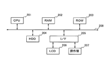
- the hardware which comprises each functional block of the rolling control apparatus 100 is demonstrated with reference to FIG.
- FIG. 2 is a block diagram showing a hardware configuration for realizing each functional block of the rolling control apparatus 100 according to the present embodiment.
- the rolling control apparatus 100 according to the present embodiment has the same configuration as an information processing terminal such as a general server or a PC (Personal Computer).
- the rolling control apparatus 100 includes a CPU (Central Processing Unit) 201, a RAM (Random Access Memory) 202, a ROM (Read Only Memory) 203, an HDD (Hard Disk Drive) 204, and an I / F 205. 208 is connected. Further, an LCD (Liquid Crystal Display) 206 and an operation unit 207 are connected to the I / F 205.
- a CPU Central Processing Unit
- RAM Random Access Memory
- ROM Read Only Memory
- HDD Hard Disk Drive
- I / F 205 I / F 205.
- the CPU 201 is a calculation means and controls the entire operation of the rolling control apparatus 100.
- the RAM 202 is a volatile storage medium capable of reading and writing information at high speed, and is used as a work area when the CPU 201 processes information.
- the ROM 203 is a read-only nonvolatile storage medium and stores a program such as firmware.
- the HDD 204 is a non-volatile storage medium capable of reading and writing information, and stores an OS (Operating System), various control programs, application programs, and the like.
- the I / F 205 connects and controls the bus 208 and various hardware and networks.
- the I / F 205 also functions as an input / output unit for the rolling control device 100 to exchange information with the rolling mill 10.
- the LCD 206 is a visual user interface for the operator to check the state of the rolling control device 100.
- the operation unit 207 is a user interface for an operator to input information to the rolling control device 100, such as a keyboard and a mouse.
- a program stored in a recording medium such as the ROM 203, the HDD 204, or an optical disk (not shown) is read to the RAM 202, and the CPU 201 performs an operation according to the program, thereby configuring a software control unit.
- the function of the rolling control apparatus 100 according to the present embodiment is realized by a combination of the software control unit configured as described above and hardware.
- the gist according to the present embodiment is that the setting of the rolling conditions by the setup calculation unit 105, the determination of the set plate thickness by the reduction ratio change specification calculation unit 108 and the set plate thickness change unit 109, and The learning of the rolling model is based on the calculation of the friction coefficient ⁇ and the deformation resistance k in the rolling operation under the rolling conditions thus determined.
- the operation according to the gist of the present embodiment will be described.
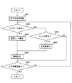
- FIG. 3 is a flowchart showing the operation mode determination operation by the setup calculation unit 105.
- the setup calculation unit 105 determines that the material type of the coil to be rolled next is the same as the material type of the coil of the material to be rolled currently being rolled. It is determined whether or not there is (S301). The material type of the coil to be rolled is input to the rolling control device 100 by the operator's manual work.
- the setup calculation unit 105 determines whether or not it is set to perform the rolling operation in the coil learning mode (S302). As a result of the determination in S302, if it is not in every coil learning mode (S302 / NO), the setup calculation unit 105 determines that it is a normal rolling mode (S304), and ends the process.
- FIG. 4 shows “line speed”, “mode judgment timing”, “set plate thickness change timing”, “set plate thickness change amount”, “integrator reset timing”, “parameter calculation timing” in the learning rolling mode. , Shows a timing chart showing “rolling load model calculation timing"
- the “line speed” that is the conveyance speed of the material to be rolled is periodically reduced. As described above, this is a cutting speed for cutting a material to be rolled that has been rolled in the case where continuous rolling is performed by welding and connecting different coils, and this embodiment relates to this embodiment. This is the lowest and lowest speed in the line speed control of the rolling mill 10.
- the line speed according to the present embodiment changes in each of an acceleration period in which acceleration is performed from the cut speed, a subsequent steady period, and a deceleration period in which the speed is reduced from the steady period speed to the cut speed.
- the steady speed in the steady period is a rolling speed that is a conveyance speed of the material to be rolled in a normal rolling operation
- the steady period is a normal period.
- the “line speed” shown in FIG. 4 corresponds to the roll speed for any one of the four rolling stands 1 as shown in FIG.
- the roll speed of the plurality of rolling stands 1 included in the tandem rolling mill is set higher as it is arranged in the subsequent stage.
- the Accordingly, the acceleration, steady state, and deceleration control of the line speed as shown in FIG. 4 is controlled corresponding to the difference in the roll speed for each rolling stand as described above.
- the “mode determination timing” is a timing at which the operation described with reference to FIG. 3 is executed, and is a timing before the above-described deceleration for the cutting speed is started. Note that the mode calculation timing in this embodiment is determined by the setup calculation unit 105 according to the line speed change control by the speed change unit 107.
- the “set plate thickness change timing” is a signal indicating the timing at which the roll gap control unit 111 changes the direction in which the set plate thickness for calculating ⁇ h used in feedback control is changed. Be controlled. As shown in FIG. 4, the reduction ratio change specification calculation unit 108 indicates the set plate thickness change timing by a signal indicating the timing of changing from the reference value in the positive direction and the timing of changing in the negative direction.
- the set plate thickness change timing is obtained by dividing the line speed deceleration period, the acceleration period, and the steady period into four as shown in FIG. Specifically, in the first period in which the original set plate thickness is changed to the maximum set plate thickness in the positive direction, in the negative direction, the maximum set plate thickness is changed to the original set plate thickness. During the second period, the original setting plate thickness is changed in the negative direction so as to be the minimum setting plate thickness. In the third period, the minimum setting plate thickness is changed in the positive direction so as to be the original setting plate thickness. Four periods of the fourth period are obtained by dividing each of the deceleration period, the acceleration period, and the steady period into four.
- the rolling reduction rate change specification calculation unit 108 is thicker than the standard for the first period in which the set plate thickness is increased from the standard set plate thickness in each of the acceleration period, the deceleration period, and the normal period.
- the second period to return from the set plate thickness to the standard set plate thickness, the third period to reduce the set plate thickness from the standard set plate thickness, the fourth period to return from the set plate thickness thinner than the standard to the standard set plate thickness Four periods are set.
- the “set plate thickness change amount” is a signal indicating the change amount of the set plate thickness corresponding to the “set plate thickness change timing” described above, and is controlled by the set plate thickness changing unit 109. As shown in FIG. 4, the set plate thickness changing unit 109 indicates the set plate thickness change amount by a signal indicating the change amount in the positive direction and the change amount in the negative direction from the original set plate thickness. The set plate thickness changing unit 109 obtains the “set plate thickness change timing” and the change rate of the reduction rate from the reduction rate change specification calculating unit 108 and calculates the “set plate thickness change amount”.
- the rolling mill 10 includes four rolling stands 1, but the “set plate thickness change amount” shown in FIG. 4 is set based on the change in line speed as shown in FIG. In accordance with the “set plate thickness change timing”, the roll gap control for each rolling stand 1 is applied at the same timing.
- “Integrator reset timing” is a reset signal indicating the timing at which the integrator reset unit 110 resets the integration period by the roll gap control unit 111, and is controlled by the integrator reset unit 110.
- the integrator reset unit 110 refers to the “set plate thickness change amount” output from the set plate thickness change unit 109, and changes the “set plate thickness change amount” change rate, that is, the “set plate thickness change amount”.
- a reset signal is output at the timing when "" changes into a crank shape.
- the “parameter calculation timing” is a signal indicating a period during which the friction coefficient calculation unit 102 and the deformation resistance calculation unit 103 calculate the friction coefficient ⁇ and the deformation resistance k, and the friction coefficient calculation unit 102 and the deformation resistance calculation unit 103 respectively. Be controlled. As shown in FIG. 4, the “parameter calculation timing” according to the present embodiment is set with an acceleration period, a steady period, and a deceleration period as one cycle.
- Rolling load model calculation timing is a signal indicating the timing at which the rolling load calculation unit 104 calculates the rolling load model based on the parameters calculated by the friction coefficient calculation unit 102 and the deformation resistance calculation unit 103. It is controlled by the calculation unit 104.
- h 0 to h 4 under various rolling conditions can be obtained by performing the rolling operation while changing the set plate thickness according to the acceleration period, the steady period, and the deceleration period of the line speed.
- the gist of the present embodiment is to obtain information of P 1 to P 4 and RV 1 to RV 4 and calculate parameters.
- the integrator reset unit 110 also outputs a reset signal at a predetermined timing for the feedback control for the fourth rolling stand 1.
- This predetermined timing means that the portion where the plate thickness of the material to be rolled changes into a crank shape by rolling according to the “set plate thickness change amount” in FIG. This is the timing to reach the rolling stand 1.
- the integrator reset unit 110 outputs an integration reset signal for the feedback control for the third rolling stand 1 and then delays it for the period obtained by the above calculation to delay the fourth rolling stand 1.
- a reset signal is output in response to feedback control.
- FIG. 4 The calculation of “set plate thickness change timing” and “set plate thickness change amount” shown in FIG. 4 is one of the gist according to the present embodiment.
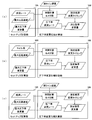
- FIGS. 5A to 5C calculation modes of “set plate thickness change timing” and “set plate thickness change amount” will be described.
- FIGS. 5A to 5C are functional block diagrams showing calculation modes of “set plate thickness change timing” and “set plate thickness change amount” by the setup calculation unit 105 and the reduction rate change specification calculation unit 108. FIG. .
- FIG. 5A is a diagram illustrating a calculation mode of “set plate thickness change timing” and “set plate thickness change amount” in the acceleration period of the line speed.
- the acceleration rate, the maximum rolling speed, and the maximum reduction rate change amount are input from the setup calculation unit 105 to the reduction rate change specification calculation unit 108.
- the rolling rate monitoring specification unit 101 receives line speed measurement values RV 1 to RV 4 as current line speeds.
- the calculation timing of the rolling load model in this embodiment is the period when the line speed has fallen to the cutting speed. Therefore, the measured values RV 1 to RV 4 of the line speed input from the rolling state monitoring unit 101 to the reduction rate change specification calculating unit 108 as the current line speed are the cutting speeds.
- the reduction ratio change specification calculation unit 108 calculates the time required for the acceleration of the line speed, that is, the acceleration period described in FIG. 4 based on the current line speed, the acceleration rate, and the maximum rolling speed among the input information. As described with reference to FIG. 4, the “set plate thickness change timing” is calculated by dividing the time into four. That is, the acceleration rate and the maximum rolling speed shown in FIG. 5A are information for setting a time-series change in the conveyance speed of the material to be rolled, and the setup calculation unit 105 functions as a conveyance speed setting unit. .
- the rolling reduction rate change specification calculation unit 108 is configured to set the “setting plate thickness changing timing” based on the maximum rolling reduction rate change amount and the predetermined rolling reduction rate change rate input from the setup calculation unit 105 and the “set plate thickness change timing” calculated above. “Thickness change amount” is calculated. That is, the rolling reduction rate change specification calculation unit 108 functions as a set plate thickness change setting unit that sets time-series changes in the set plate thickness.
- the predetermined reduction rate change rate will be described with reference to FIG.
- the first to third rolling stands 1 are conveyed to the fourth rolling stand 1 by performing learning rolling as shown in FIG. 4, that is, rolling while changing the set plate thickness.
- learning rolling as shown in FIG. 4, that is, rolling while changing the set plate thickness.
- a material to be rolled whose thickness changes in a crank shape according to the position in the direction is supplied.
- the product plate thickness needs to be realized in the fourth rolling stand 1.
- FIG. 6 is a diagram showing an example of changes in the inlet side plate thickness and the outlet side plate thickness in the case of performing feedback control as in the above equation (2).
- a deviation g corresponding to the change rate of the inlet side plate thickness occurs at the crank side change point in the outlet side plate thickness. This always occurs as long as the control based on the integral calculation as shown in Expression (2) is performed.
- the reduction rate change rate set in the reduction rate change specification calculation unit 108 is the rate of change of the outlet side plate thickness of the third rolling stand 1 so that no off gauge is generated in the outlet side plate thickness of the fourth rolling stand 1. It is.
- the maximum reduction rate change amount input from the setup calculation unit 105 is a threshold set by the setup calculation unit 105 in order to avoid the occurrence of slip.
- the setup calculation unit 105 sets a threshold value for the change amount of the reduction ratio as the maximum reduction ratio change amount, and prevents the occurrence of slip.
- FIG. 7 is a diagram showing a mode in which the “set plate thickness change amount” is obtained based on the reduction rate change rate, the set plate thickness change timing, and the maximum reduction rate change amount.
- the “set plate thickness change amount” can be typically obtained as a “calculation result” shown in FIG. 7 based on the rolling reduction rate change rate and the set plate thickness change timing.
- the rolling reduction rate change specification calculation unit 108 applies the maximum rolling reduction rate change amount input from the setup calculation unit 105 and sets the “set plate thickness change amount” obtained as the “calculation result” as a threshold value. If there is a portion exceeding the maximum reduction rate change amount, the result corrected as “actual” in FIG. 7 is calculated as “set plate thickness change amount”.
- FIG. 5B is a diagram showing a calculation mode of “set plate thickness change timing” and “set plate thickness change amount” in the steady period of the line speed.
- the coil length and the maximum rolling speed are input from the setup calculation unit 105 to the reduction rate change specification calculation unit 108.
- the time required for the normal rolling that is, the normal period described in FIG. 4 is calculated based on the coil length and the maximum rolling speed among the input information.
- “set plate thickness change timing” and “set plate thickness change amount” are calculated.
- FIG. 5C is a diagram showing a calculation mode of “set plate thickness change timing” and “set plate thickness change amount” during the line speed deceleration period.
- the deceleration rate, the maximum rolling speed, and the maximum reduction rate change amount are input from the setup calculation unit 105 to the reduction rate change specification calculation unit 108.
- the rolling rate monitoring specification unit 101 receives line speed measurement values RV 1 to RV 4 as current line speeds.
- the reduction rate change specification calculation unit 108 determines the time required for the line speed to be reduced based on the current line speed, the deceleration rate, and the cut speed in the input information, that is, the deceleration period described in FIG.
- “set plate thickness change timing” and “set plate thickness change amount” are calculated.
- the calculation timing of the rolling load model is a period during which the line speed falls to the cutting speed, it is input from the rolling state monitoring unit 101 to the reduction rate change specification calculation unit 108 as the current line speed.
- the measured values RV 1 to RV 4 of the line speed are cut speeds.
- the cutting speed may be input from the setup calculation unit 105 to the reduction ratio change specification calculation unit 108.
- the set plate thickness is set for each acceleration period, steady period, and deceleration period of the line speed.
- the rolling operation is started, and the reduction of the rolling reduction is started by the rolling model set by the setup calculation unit 105.
- the abnormality monitoring unit 112 detects an off-gauge based on the measured values of the rolling state such as h 0 to h 4 , P 1 to P 4 , RV 1 to RV 4 and the like input from the rolling state monitoring unit 101 (S802 / YES) ), Notification of the off-gage occurrence and the rolling state at the occurrence of the off-gauge to the reduction rate change amount correcting unit 113.
- the reduction rate change amount correction unit 113 corrects the reduction rate change rate stored in the reduction rate change specification calculation unit 108 so that the off-gauge is eliminated (S803).
- the abnormality monitoring unit 112 notifies the rolling reduction change amount correcting unit 113 of the occurrence of the slip and the rolling state at the time of the occurrence of the slip.
- the reduction rate change amount correction unit 113 inputs the maximum reduction rate change amount corrected so as to eliminate the slip to the reduction rate change specification calculation unit 108 (S805).
- the abnormality detection unit 112 controls the alarm output unit 114 to output an alarm (S806).
- the abnormality detection unit 112 repeats the process from S802 until the reduction of the rolling reduction is completed (S807 / NO), and ends the process when the change of the rolling reduction is completed (S807 / YES).
- the parameters under various rolling conditions can be collected by changing the rolling reduction of the first to third rolling stands in time series. Described as an example. However, this is only an example, and control in other rolling stands is optional as long as the target plate thickness of the product is controlled in at least the last rolling stand.
- Embodiment 2 FIG. In the first embodiment, as described with reference to FIG. 6, an example has been described in which the rolling reduction rate change rate is determined so that the deviation g generated in the outlet side plate thickness of the fourth rolling stand does not become an off gauge. There is no problem as long as sufficient samples can be collected by this rolling reduction rate change rate. However, if the rolling reduction rate change rate is determined after the set plate thickness changing timing is determined as shown in FIG. 4, the rolling reduction rate may be changed. The possible range is determined. If the range is not sufficient, sufficient samples cannot be collected.
- the deviation g as shown in FIG. 6 is absorbed by performing feedback control of the rolling stand 1 not by the integral equation as shown in the above equation (2) but by the double integral equation. Is possible. Therefore, when the roll gap control unit 111 performs feedback control by double integration, the reduction rate change specification calculation unit 108 changes the reduction rate at a rate higher than a predetermined reduction rate change rate. The “thickness change amount” may be obtained, and further, a predetermined reduction rate change rate may be omitted.
- the case where the range is not sufficient means, for example, a case where the maximum amount of change in the reduction rate determined by the set plate thickness change timing and the reduction rate change rate is less than the maximum reduction rate change amount input from the setup calculation unit 105.
- the maximum reduction rate change amount is 70%, 80%, or the like, which is less than a predetermined ratio.
- Embodiment 3 The problem of the deviation g as described with reference to FIG. 6 is caused by the feedback corresponding to the change in the entrance side plate thickness.
- the entrance side plate thickness in the 4th rolling stand 1 is the exit side plate thickness in the 3rd rolling stand 1
- the change of the entrance side plate thickness in the 4th rolling stand 1 can be detected in advance. Feed forward control can be performed.
- the roll gap control unit 111 performs feedforward control according to the exit side plate thickness of the third rolling stand 1,
- the deviation g as shown in FIG. 6 can be eliminated. This eliminates the need to control the rate of change of the outlet side plate thickness of the third rolling stand 1 in order to cope with the deviation g as shown in FIG.
- the “set plate thickness change amount” can be calculated so that the rolling reduction is changed at a desired rate.
- Embodiment 4 In the first embodiment, on the premise of an acceleration period from the cutting speed, a steady period, and a deceleration period to the cutting speed, various data samples are collected by changing the set plate thickness into a crank shape for each period.
- the embodiment has been described.
- the samples collected in the low speed period of the line speed are only just before the end of the deceleration period and immediately after the start of the acceleration period. Therefore, in order to increase the number of samples in the low speed period, the line speed may be changed for data sample collection, instead of determining the steady period other than the acceleration period from the cut speed and the deceleration period to the cut speed.
- FIG. 9 is a timing chart in the learning rolling mode and corresponds to FIG.
- the line speed also changes during the period T, which is the steady period in FIG.
- the change rate of the line speed changes in accordance with the timing when the set plate thickness change amount changes in a crank shape.
Landscapes
- Engineering & Computer Science (AREA)
- Mechanical Engineering (AREA)
- Control Of Metal Rolling (AREA)
Abstract
L'invention a pour objet un appareil, un procédé et un programme servant à acquérir des échantillons de données dans différentes conditions sans compromettre la qualité du produit au cours d'une opération de laminage. Pour ce faire, la présente invention comprend : une unité de commande d'espace de laminage (111) qui commande un espace de laminage d'une pluralité de socles de laminage (1) par le biais d'une commande en circuit fermé de sorte qu'une épaisseur de plaque d'un matériau laminé qui est laminé par la pluralité de socles de laminages (1) se rapproche d'une épaisseur de plaque prédéfinie ; une unité de calcul de réglage (105) qui règle un changement de vitesse linéaire ; une unité de calcul de spécification de changement de réduction de laminage (108) qui règle un changement séquentiel de l'épaisseur de plaque prédéfinie pour commander l'espace de laminage de la pluralité de socles de laminage (1) autre que celui le plus en arrière sur la base du changement séquentiel de la vitesse linéaire ; et une unité de calcul de coefficient de frottement (102) et une unité de calcul de résistance à la déformation (103) qui calculent un coefficient de frottement et une résistance à la déformation sur la base d'une valeur mesurée réelle d'un état de laminage du laminage effectué sur la base de l'épaisseur de plaque prédéfinie et de la vitesse linéaire réglée pour changer séquentiellement.
Priority Applications (3)
| Application Number | Priority Date | Filing Date | Title |
|---|---|---|---|
| JP2013505633A JP5631481B2 (ja) | 2011-03-18 | 2011-03-18 | 圧延制御装置、圧延制御方法および圧延制御プログラム |
| PCT/JP2011/056590 WO2012127571A1 (fr) | 2011-03-18 | 2011-03-18 | Appareil de commande de laminage, procédé de commande de laminage et programme de commande de laminage |
| CN201180067985.4A CN103384572B (zh) | 2011-03-18 | 2011-03-18 | 轧制控制装置、轧制控制方法以及轧制控制程序 |
Applications Claiming Priority (1)
| Application Number | Priority Date | Filing Date | Title |
|---|---|---|---|
| PCT/JP2011/056590 WO2012127571A1 (fr) | 2011-03-18 | 2011-03-18 | Appareil de commande de laminage, procédé de commande de laminage et programme de commande de laminage |
Publications (1)
| Publication Number | Publication Date |
|---|---|
| WO2012127571A1 true WO2012127571A1 (fr) | 2012-09-27 |
Family
ID=46878768
Family Applications (1)
| Application Number | Title | Priority Date | Filing Date |
|---|---|---|---|
| PCT/JP2011/056590 Ceased WO2012127571A1 (fr) | 2011-03-18 | 2011-03-18 | Appareil de commande de laminage, procédé de commande de laminage et programme de commande de laminage |
Country Status (3)
| Country | Link |
|---|---|
| JP (1) | JP5631481B2 (fr) |
| CN (1) | CN103384572B (fr) |
| WO (1) | WO2012127571A1 (fr) |
Cited By (4)
| Publication number | Priority date | Publication date | Assignee | Title |
|---|---|---|---|---|
| JP2014108451A (ja) * | 2012-12-04 | 2014-06-12 | Jfe Steel Corp | タンデム圧延機のライン加速時の最高圧延速度設定支援方法及び装置 |
| CN104908145A (zh) * | 2014-03-12 | 2015-09-16 | 佛山市恒力泰机械有限公司 | 一种通过储存和调用参数组合的压制方法 |
| CN113210438A (zh) * | 2021-05-20 | 2021-08-06 | 广西北港不锈钢有限公司 | 一种不锈钢冷轧薄板的高速轧制方法 |
| CN118616676A (zh) * | 2024-08-12 | 2024-09-10 | 东北大学 | 连铸圆坯凝固末端压下时机确定方法及装置、介质、设备 |
Families Citing this family (8)
| Publication number | Priority date | Publication date | Assignee | Title |
|---|---|---|---|---|
| JP6438753B2 (ja) * | 2014-12-05 | 2018-12-19 | 株式会社日立製作所 | タンデム圧延ミルの制御装置およびタンデム圧延ミルの制御方法 |
| JP2016157313A (ja) * | 2015-02-25 | 2016-09-01 | 東芝三菱電機産業システム株式会社 | 鉄鋼プラントの傾向監視装置 |
| JP6404195B2 (ja) * | 2015-09-16 | 2018-10-10 | 株式会社日立製作所 | プラント制御装置、圧延制御装置、プラント制御方法およびプラント制御プログラム |
| JP6672094B2 (ja) * | 2016-07-01 | 2020-03-25 | 株式会社日立製作所 | プラント制御装置、圧延制御装置、プラント制御方法およびプラント制御プログラム |
| JP6674349B2 (ja) * | 2016-07-21 | 2020-04-01 | 株式会社日立製作所 | 圧延制御装置、圧延制御方法およびプログラム |
| JP7034046B2 (ja) * | 2018-10-05 | 2022-03-11 | 株式会社日立製作所 | 制御装置および制御方法 |
| KR102398307B1 (ko) * | 2019-03-26 | 2022-05-16 | 도시바 미쓰비시덴키 산교시스템 가부시키가이샤 | 이상 판정 지원 장치 |
| CN114466711B (zh) * | 2020-09-04 | 2023-11-28 | 东芝三菱电机产业系统株式会社 | 冷连轧机的控制系统 |
Citations (3)
| Publication number | Priority date | Publication date | Assignee | Title |
|---|---|---|---|---|
| JP2004050211A (ja) * | 2002-07-18 | 2004-02-19 | Toshiba Mitsubishi-Electric Industrial System Corp | 圧延プロセスのモデル学習装置 |
| WO2009113719A1 (fr) * | 2008-03-14 | 2009-09-17 | 新日本製鐵株式会社 | Procédé d'apprentissage de prédiction de pression de laminage pour laminage de tôles fortes à chaud |
| JP2010036220A (ja) * | 2008-08-05 | 2010-02-18 | Kobe Steel Ltd | 圧延条件演算装置および該方法ならびに圧延システム |
Family Cites Families (5)
| Publication number | Priority date | Publication date | Assignee | Title |
|---|---|---|---|---|
| CN1234476C (zh) * | 2002-02-06 | 2006-01-04 | 中国第二重型机械集团公司 | 控制板形和板厚的轧制方法及适于该方法的无间隙轧机 |
| JP4227497B2 (ja) * | 2003-10-15 | 2009-02-18 | 株式会社日立製作所 | 圧延機のフィードフォワード板厚制御装置及びその制御方法 |
| CN100369683C (zh) * | 2006-01-24 | 2008-02-20 | 东北大学 | 一种快速高精度板带轧制过程自动控制厚度的方法 |
| JP2007245204A (ja) * | 2006-03-16 | 2007-09-27 | Jfe Steel Kk | 圧延荷重モデルの学習方法及びその装置 |
| JP2009208115A (ja) * | 2008-03-04 | 2009-09-17 | Kobe Steel Ltd | 圧延制御パラメータの算出方法及び算出装置、圧延シミュレーション装置 |
-
2011
- 2011-03-18 WO PCT/JP2011/056590 patent/WO2012127571A1/fr not_active Ceased
- 2011-03-18 CN CN201180067985.4A patent/CN103384572B/zh active Active
- 2011-03-18 JP JP2013505633A patent/JP5631481B2/ja active Active
Patent Citations (3)
| Publication number | Priority date | Publication date | Assignee | Title |
|---|---|---|---|---|
| JP2004050211A (ja) * | 2002-07-18 | 2004-02-19 | Toshiba Mitsubishi-Electric Industrial System Corp | 圧延プロセスのモデル学習装置 |
| WO2009113719A1 (fr) * | 2008-03-14 | 2009-09-17 | 新日本製鐵株式会社 | Procédé d'apprentissage de prédiction de pression de laminage pour laminage de tôles fortes à chaud |
| JP2010036220A (ja) * | 2008-08-05 | 2010-02-18 | Kobe Steel Ltd | 圧延条件演算装置および該方法ならびに圧延システム |
Cited By (5)
| Publication number | Priority date | Publication date | Assignee | Title |
|---|---|---|---|---|
| JP2014108451A (ja) * | 2012-12-04 | 2014-06-12 | Jfe Steel Corp | タンデム圧延機のライン加速時の最高圧延速度設定支援方法及び装置 |
| CN104908145A (zh) * | 2014-03-12 | 2015-09-16 | 佛山市恒力泰机械有限公司 | 一种通过储存和调用参数组合的压制方法 |
| CN113210438A (zh) * | 2021-05-20 | 2021-08-06 | 广西北港不锈钢有限公司 | 一种不锈钢冷轧薄板的高速轧制方法 |
| CN118616676A (zh) * | 2024-08-12 | 2024-09-10 | 东北大学 | 连铸圆坯凝固末端压下时机确定方法及装置、介质、设备 |
| CN118616676B (zh) * | 2024-08-12 | 2024-11-15 | 东北大学 | 连铸圆坯凝固末端压下时机确定方法及装置、介质、设备 |
Also Published As
| Publication number | Publication date |
|---|---|
| JP5631481B2 (ja) | 2014-11-26 |
| CN103384572A (zh) | 2013-11-06 |
| CN103384572B (zh) | 2015-05-27 |
| JPWO2012127571A1 (ja) | 2014-07-24 |
Similar Documents
| Publication | Publication Date | Title |
|---|---|---|
| JP5631481B2 (ja) | 圧延制御装置、圧延制御方法および圧延制御プログラム | |
| KR101958794B1 (ko) | 플랜트 제어 장치, 압연 제어 장치, 플랜트 제어 방법 및 플랜트 제어 프로그램 | |
| JP5961103B2 (ja) | 圧延制御装置、圧延制御方法および圧延制御プログラム | |
| JP6404195B2 (ja) | プラント制御装置、圧延制御装置、プラント制御方法およびプラント制御プログラム | |
| EP3025798B1 (fr) | Dispositif et procédé de commande de laminage | |
| US11487275B2 (en) | Analyzer | |
| CN101842173A (zh) | 板材轧制机及其控制方法 | |
| KR20160057992A (ko) | 압연 제어 장치, 압연 제어 방법 및 기록매체 | |
| KR20150020061A (ko) | 압연 제어 장치, 압연 제어 방법 및 기록 매체 | |
| CN103316927B (zh) | 轧制控制装置及轧制控制方法 | |
| KR101782281B1 (ko) | 압연 라인의 에너지 소비량 예측 장치 | |
| JP4227497B2 (ja) | 圧延機のフィードフォワード板厚制御装置及びその制御方法 | |
| JP2015166093A (ja) | 圧延制御装置、圧延制御方法および圧延制御プログラム | |
| CN111495981B (zh) | 设备控制装置以及轧制控制装置 | |
| CN114007770B (zh) | 轧制设备的运转辅助方法及运转辅助装置以及轧制设备 | |
| CN113042543B (zh) | 一种轧机辊缝调整方法、装置及存储介质 | |
| JP6324259B2 (ja) | 圧延制御装置、圧延制御方法および圧延制御プログラム | |
| JP2009034730A (ja) | タンデム圧延機の張力制御装置 | |
| JP6356094B2 (ja) | 圧延制御装置及び圧延制御方法 | |
| JP6823466B2 (ja) | 圧延機の板厚制御装置および該方法ならびに圧延機 | |
| JP6373800B2 (ja) | 圧延制御装置、圧延制御方法および圧延制御プログラム | |
| JP2018122339A (ja) | 板厚制御方法、板厚制御装置、冷間圧延設備および鋼板の製造方法 | |
| JP2004050217A (ja) | タンデム圧延機の張力制御装置 | |
| JP6057774B2 (ja) | 圧延機におけるミル伸び式の同定方法 | |
| JP6189695B2 (ja) | ワイヤ送給装置 |
Legal Events
| Date | Code | Title | Description |
|---|---|---|---|
| 121 | Ep: the epo has been informed by wipo that ep was designated in this application |
Ref document number: 11861476 Country of ref document: EP Kind code of ref document: A1 |
|
| ENP | Entry into the national phase |
Ref document number: 2013505633 Country of ref document: JP Kind code of ref document: A |
|
| NENP | Non-entry into the national phase |
Ref country code: DE |
|
| 122 | Ep: pct application non-entry in european phase |
Ref document number: 11861476 Country of ref document: EP Kind code of ref document: A1 |