WO2012127605A1 - Dispositif de traitement d'informations et procédé de traitement d'informations - Google Patents
Dispositif de traitement d'informations et procédé de traitement d'informations Download PDFInfo
- Publication number
- WO2012127605A1 WO2012127605A1 PCT/JP2011/056784 JP2011056784W WO2012127605A1 WO 2012127605 A1 WO2012127605 A1 WO 2012127605A1 JP 2011056784 W JP2011056784 W JP 2011056784W WO 2012127605 A1 WO2012127605 A1 WO 2012127605A1
- Authority
- WO
- WIPO (PCT)
- Prior art keywords
- screen
- content
- camera
- reference line
- route
- Prior art date
- Legal status (The legal status is an assumption and is not a legal conclusion. Google has not performed a legal analysis and makes no representation as to the accuracy of the status listed.)
- Ceased
Links
Images


Classifications
-
- G—PHYSICS
- G06—COMPUTING OR CALCULATING; COUNTING
- G06T—IMAGE DATA PROCESSING OR GENERATION, IN GENERAL
- G06T11/00—Two-dimensional [2D] image generation
-
- G—PHYSICS
- G06—COMPUTING OR CALCULATING; COUNTING
- G06V—IMAGE OR VIDEO RECOGNITION OR UNDERSTANDING
- G06V20/00—Scenes; Scene-specific elements
- G06V20/20—Scenes; Scene-specific elements in augmented reality scenes
-
- G—PHYSICS
- G06—COMPUTING OR CALCULATING; COUNTING
- G06V—IMAGE OR VIDEO RECOGNITION OR UNDERSTANDING
- G06V30/00—Character recognition; Recognising digital ink; Document-oriented image-based pattern recognition
- G06V30/10—Character recognition
- G06V30/14—Image acquisition
- G06V30/142—Image acquisition using hand-held instruments; Constructional details of the instruments
Definitions
- the present invention relates to an information processing apparatus and an information processing method.
- Patent Document 1 a camera built in a portable device recognizes a specific object in the field of view of the camera, and the portable device creates an appropriate computer graphic based on this recognition.
- it is disclosed to superimpose on a real-world image displayed on a display device.
- FIG. 1 shows an example in which content related to a place is displayed superimposed on the video of the camera.
- an object of the present invention is to provide a technology for displaying content at an appropriate position in a technology for displaying content superimposed on a camera image.
- the present invention employs the following means. That is, the present invention accesses a camera that captures a real space, a display unit that displays a video related to the real space captured by the camera, and a storage device that stores content to be displayed over the video, and Based on position information including the position and orientation of the camera, among the objects included in the video, the position information of the object that displays the content, the acquisition unit that acquires the content, and the content acquired by the acquisition unit
- a control unit that superimposes the image on the video and displays the image on the display unit, the control unit sets an azimuth reference line related to an azimuth and a distance reference line related to a distance on the screen, and the position information of the camera and the Based on the position information of the object, the position of the object with respect to the camera is calculated, and based on the azimuth reference line, the position of the object on the screen is calculated. Identify a flat position, the distance based on the reference line identifies the vertical position of the object in the
- the position of the object relative to the camera can be specified both horizontally and vertically on the screen. That is, the content can be displayed at an appropriate position.
- the position in the vertical direction is not particularly taken into consideration, and when content overlaps in the same direction, the content of the object close to the camera is displayed in the foreground to prevent it from being displayed overlapping. It was only.
- the content can be displayed at an appropriate position including the vertical direction.
- the present invention can be widely applied to technologies relating to augmented reality (hereinafter also referred to as AR technology).
- the present invention can be suitably used for navigation technology using AR technology.
- the present invention can be widely applied as an apparatus including a camera, a communication function, and a computer, but can be particularly preferably used as a mobile terminal such as a smart phone or a mobile phone.
- the control unit sets an azimuth reference line related to an azimuth and a distance reference line related to a distance to the screen, and sets the position information of the camera and the position information of the object. Based on the angle of the object with respect to the optical axis of the camera and the distance from the camera to the object, to determine the horizontal position of the object on the screen based on the azimuth reference line, A vertical position of the object on the screen may be specified based on a distance reference line, and a display position of the object on the screen may be specified.
- the optical axis of the camera means an axis that passes through the center of the camera lens and is orthogonal to the plane of the lens.
- the distance from the camera to the object means a horizontal distance.
- the position information of the target object includes position information of three or more target points that specify the shape of the target object
- the control unit includes each of the target points.
- the horizontal position and the vertical position on the screen can be specified
- the plane can be set by connecting the specified target points
- the text can be set on the set plane.
- the degree of freedom of content display is limited, and only balloons, pins, photos, icons, etc. can be displayed.
- not only the horizontal position but also the vertical position can be displayed on the screen with high accuracy, so that the content can be displayed in various forms that are not conventional, such as a form that matches the shape of the building. Can do.
- the control unit analyzes the video and sets a boundary reference line including a scene boundary constituting the real space for the screen. Then, the content display position may be corrected based on the boundary reference line.
- the boundary reference line By calculating the boundary reference line and correcting the display position of the content based on the reference line, it is possible to display the content at an appropriate position in an easy-to-see manner. For example, by providing a boundary reference line as a road boundary and arranging the content so that only the content related to the road is displayed in the road, it is possible to make it easier to see.
- the control unit analyzes a boundary of a scenery to be displayed with priority over other scenery among the scenery constituting the real space by analyzing the video.
- a line may be set for the screen, and the content display position may be corrected based on the priority boundary reference line.
- the scenery to be displayed with priority over other scenery can be preset according to the purpose. For example, when the present invention is used as a navigation technique using the AR technique, “road” can be set as a scenery to be displayed with priority over other scenery. As a result, the “road” that is most important for navigation can be displayed with priority and reliability. Examples of other scenery include buildings and trees.
- the information processing apparatus functions as a navigation device, and the control unit calculates the boundary line of the road by analyzing the video as the boundary reference line, and within the boundary line of the road.
- the content other than the content related to the road can be arranged outside the boundary reference line corresponding to the boundary line of the road.
- control unit may calculate a horizontal line passing through the focal point of the road boundary line, and sequentially arrange contents other than the content related to the road with the horizontal line as a base line. By arranging sequentially from the horizontal line, it is possible to make the display easier to see.
- control unit may analyze the video to calculate a ridge line including a contour of a natural object including a tree and a mountain, and dispose content related to the natural object above the ridge line. .
- the display position of the content related to the artificial structure such as a building can be distinguished from the display position of the content related to the natural object, and the display can be made easier to see.
- the ridgeline may include a ridgeline as a building outline in part.
- the present invention can also be specified as an information processing method executed by the information processing apparatus described above.
- the present invention is an information processing method executed by an information processing apparatus including a camera that captures a real space, and a display unit that displays a video related to the real space captured by the camera. Based on the position information including the position and orientation of the camera, the storage device storing the content to be displayed in a superimposed manner is accessed, and the position information of the object for displaying the content among the objects included in the video, and the An acquisition step of acquiring content, and a control step of displaying the content acquired in the acquisition step on the video image on the display unit, wherein the control step includes a azimuth reference line related to a direction and a distance related to a distance.
- a reference line is set on the screen, and based on the position information of the camera and the position information of the object, Calculating the position of the object, specifying the horizontal position of the object on the screen based on the azimuth reference line, specifying the vertical position of the object on the screen based on the distance reference line, The display position of the object on the screen is specified.
- the present invention can also be specified as an information processing system including the information processing apparatus described above and a content management server that provides content to such an information processing apparatus. Further, the present invention may be specified as an information processing method executed in the information processing system. Further, the present invention may be specified as a program that realizes processing executed by the information processing apparatus or the information processing system or a computer-readable recording medium that records such a program. In this case, the function can be provided by causing a computer or the like to read and execute the program of the recording medium.
- a computer-readable recording medium is a recording medium that accumulates information such as data and programs by electrical, magnetic, optical, mechanical, or chemical action and can be read from a computer or the like. Say.
- the content can be displayed at an appropriate position in the technology for displaying the content superimposed on the video of the camera.
- FIG. 1 shows a configuration of an information processing system according to a first embodiment.
- the functional block diagram of the portable terminal which concerns on 1st embodiment is shown.
- the functional block diagram of a content management server is shown.
- storage part of a content management server is shown.
- storage part of a content management server is shown.
- the screen transition diagram of a portable terminal is shown. Show the home screen. Opening screen is shown.
- the application selection screen is shown. An operation explanation screen is shown. The region (prefecture) selection screen is shown. The district (city) selection screen is shown. The user input screen is shown.
- the route list screen is shown. Shows the map screen. A camera guidance screen is shown. A menu screen is shown. The language selection screen is shown. The route details screen is shown. The balloon display change screen is shown. An information details screen is shown. The radar range change screen is shown.
- the content management processing flow is shown. The content change processing flow is shown. A content management screen is shown. The content registration screen is shown. The content search screen is shown. The content search result screen is shown. A content change screen (basic information) is shown. A content change screen (additional information) is shown. The route registration processing flow is shown. The route change processing flow is shown. The route management screen is shown. The route registration screen (basic information) is shown. A route registration screen (content list) is shown. The route confirmation screen is shown.
- the route search screen is shown.
- the route search result list screen is shown.
- the route change screen (basic information) is shown.
- the search processing flow for root content is shown.
- the display processing flow of a camera guidance screen is shown.
- An image for determining an angle when “target point” is displayed is shown.
- An image for determining the distance when displaying the “target point” is shown.
- Sectional drawing explaining the relationship between a camera and "target point A" is shown.
- a state in which the content is temporarily positioned on the video is shown.
- An analysis of the intensity of each pixel in the image and calculation of a ridgeline, a road boundary line, and a horizontal line are shown.
- the manner in which the display position of the content is corrected is shown.
- the display example of a camera guidance screen is shown.
- a mode that the target point of a horizontal position is specified is shown.
- a mode that the target point of a height position is specified is shown.
- a state where an outline is specified by connecting four target points is shown.
- a state in which an area specified by connecting four target points is specified as a surface is shown. Shows how to set text for a specified face.
- FIG. 2 shows a configuration of the information processing system 1 according to the first embodiment.
- An information processing system 1 according to the first embodiment includes a mobile terminal 2 and a content management server 3.
- the portable terminal 2 and the content management server 3 are connected to each other via a network.
- the network is exemplified by the Internet using a telephone line network, but the network is not particularly limited as long as the mobile terminal 2 and the content management server 3 can be electrically connected to enable communication.
- FIG. 2 only one portable terminal 2 is shown, but a plurality of portable terminals 2 can be provided.
- the portable terminal 2 functions as a navigation device by installing a predetermined application in advance.
- the mobile terminal 2 is exemplified by a smartphone (for example, Android mobile phone (Android: registered trademark) or iphone (registered trademark)).
- FIG. 3 shows a functional block diagram of the mobile terminal 2 according to the first embodiment.
- the mobile terminal 2 includes a control unit 21, an operation unit 22, a display unit 23, a camera 24, a communication unit 25, a position information acquisition unit 26, an orientation sensor 27, and a storage unit 28.
- the control unit 21 of the mobile terminal controls each unit of the mobile terminal 2 based on information from the content management server 3 and a user (user) operation instruction.
- the control unit 21 of the mobile terminal includes a CPU 211 of the mobile terminal and a memory 212 of the mobile terminal.
- the CPU 211 of the portable terminal controls each hardware of the portable terminal 2 and functions as a portable terminal having a navigation function using the AR technology according to a control program recorded in the memory 212 of the portable terminal.
- each function unit can be configured as a computer program executed on the CPU 211 of the mobile terminal, and each of these function units may be configured as a dedicated processor or configured as one processor. May be.
- the memory 212 of the portable terminal is a memory (storage medium) that stores various data and control programs, and is configured by a rewritable flash memory or the like.
- Each function unit is exemplified below. That is, the analysis unit analyzes the video and calculates a reference line including the boundary of the scenery that forms the real space.
- the arrangement unit arranges the content based on the reference line calculated by the analysis unit.
- the navigation unit displays the route to the destination, and displays the content superimposed on the video captured by the camera 24 based on the analysis results of the analysis unit and the arrangement unit.
- the operation unit 22 of the mobile terminal receives an instruction from the user.
- the operation unit 22 of the mobile terminal is configured by, for example, a touch panel, a push button, or the like.
- the operation unit 22 of the mobile terminal according to the present embodiment is configured by a touch panel. Signals are input to the control unit 21 of the mobile terminal according to various operations.
- the display unit 23 of the mobile terminal displays an image based on a signal from the control unit 21 of the mobile terminal.
- the display unit 113 of the portable terminal is configured by, for example, a liquid crystal display, an organic EL display, or the like.
- the display unit 23 of the mobile terminal according to the present embodiment is configured by a touch panel.
- the camera 24 shoots a real space.
- the camera 24 includes a module that has an optical system and an image receiving element and acquires a digital image.
- the acquired digital image is displayed on the display unit 23 of the mobile terminal.
- the mobile terminal 2 functions as an AR navigation device, the acquired image is stored in the storage unit 28 of the mobile terminal, and the content is superimposed and displayed on the display unit 23 of the mobile terminal.
- the communication unit 25 of the mobile terminal is connected to the network and communicates with the content management server 3 and other mobile terminals.
- the location information acquisition unit 26 detects the location of the mobile terminal based on GPS signals from one or a plurality of GPS (Global Positioning System) satellites. The position information regarding the detected position is input to the control unit 21 of the mobile terminal. As a result, the control unit 21 of the mobile terminal can grasp the position of the mobile terminal 2.
- the position information acquisition unit 26 may detect the position of the mobile terminal 2 based on signals from one or a plurality of radio communication base stations, for example. The acquisition of the position information can use existing techniques as appropriate.
- the direction sensor 27 detects the direction (horizontal direction) and angle (vertical direction) of the mobile terminal 2.
- the detected signal corresponding to the direction / angle is input to the control unit 21 of the portable terminal.
- the control unit 21 of the mobile terminal can grasp the direction / angle of the mobile terminal 2.
- the storage unit 28 of the mobile terminal stores various information.
- the storage unit 28 of the mobile terminal stores video captured by the camera 24.
- the storage unit 28 of the mobile terminal can be configured by, for example, a semiconductor memory.
- a content management server (hereinafter also simply referred to as a server) 3 manages content to be provided to the mobile terminal 2.
- FIG. 4 shows a functional block diagram of the content management server.
- the content management server 3 includes a control unit 31, an operation unit 32, a display unit 33, a communication unit 34, and a storage unit 35, and the control unit 31 includes a CPU 311 and a memory 312.
- the server operation unit 32 includes, for example, a keyboard, a pointing device, a touch panel, operation buttons, and the like.
- the server display unit 33 includes, for example, a liquid crystal display device, a plasma display panel, a CRT (Cathode Ray Tube), an electroluminescence panel, and the like.
- Examples of the communication unit 34 of the server include a communication module (for example, a network card) that realizes connection to a network.
- the server control unit 31 includes a CPU (Central Processing Unit) 311 and a memory 312.
- the CPU 311 of the server controls each hardware of the content management server 3 and causes a functional unit such as a content / route management unit to function according to a control program stored in the content management server 3.
- the functional unit can be configured as a computer program executed on the CPU 311 of the content management server.
- These functional units may be configured as a dedicated processor.
- the content / route management unit manages content and routes. Specifically, the content and route posted by the user, the recording of the received content and route in the database, the update of the database storing the content and route, the provision of the content in response to the request from the mobile terminal 2 Etc.
- the storage unit 35 of the server stores contents and routes under the control of the content / route management unit.
- the content management server 3 can be configured by a hard disk drive (hereinafter referred to as HDD), a semiconductor memory, or the like.
- FIG. 5A shows an example of a content management database stored in the storage unit 35 of the server.
- items of “identification number”, “content”, “latitude, longitude, height” are provided, and information corresponding to each item is stored.
- the “identification number” is also referred to as a content number and is unique identification information assigned to each content.
- the “content” includes various types of information regarding the place. For example, “content” includes names of buildings, roads, trees, mountains, etc., information about history, and the like.
- the “content” is not limited to text data, and may be image data or illustration data.
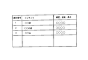
- FIG. 5B shows an example of a route management database stored in the storage unit 35 of the content management server.
- the “identification number” is also referred to as a route number, and is unique identification information assigned to each route.
- the “route” includes various information regarding the route. For example, the “route” includes an eating route, a history enjoying route, and a wallet-friendly route.
- the “content list” includes contents constituting each route.
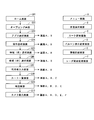
- FIG. 6 shows a screen transition diagram of the mobile terminal. 7A to 7J and FIGS. 8A to 8F show the respective screens.
- the portable terminal 2 has a screen as shown in FIG. 6 as a related screen when functioning as a navigation device using the AR technology.
- the mobile terminal 2 includes a home screen (G01), an opening screen (G02), an application selection screen (G03), an operation explanation screen (G04), a region (prefecture) selection screen (G05), and a district (city).
- Each screen display and screen transition is performed by the control unit 21 of the mobile terminal based on a signal corresponding to a user operation, that is, an operation signal from the operation unit 22 of the mobile terminal.
- a signal corresponding to a user operation that is, an operation signal from the operation unit 22 of the mobile terminal.
- the home screen (G01) is displayed when the mobile terminal 2 is activated. That is, when the mobile terminal 2 is activated and power is supplied, the control unit 21 of the mobile terminal detects this and displays the home screen on the display unit 23 of the mobile terminal. On the home screen, an icon of an application installed in the mobile terminal 2 is displayed (see FIG. 7A). When an icon of a management application that manages a plurality of applications is selected on the home screen, the screen transitions to the opening screen of the selected management application.
- the opening screen is the opening screen of the management application.
- the operation unit 22 of the mobile terminal detects this, and a corresponding operation signal is input to the control unit 21 of the mobile terminal.
- the control unit 21 of the portable terminal receives the operation signal and displays an opening screen on the display unit 23 of the portable terminal.
- a “return” button and a “Menu” button are hardware keys provided on the mobile terminal 2. By selecting the “Return” button, it is possible to transition to the previous screen.
- transition to the menu screen (A) is possible by selecting the “Menu” button.
- the opening screen is displayed for a few seconds, and then automatically transitions to the app selection screen.
- the application selection screen (G03) is an application selection screen.
- “navigation application” and “other application” are displayed (see FIG. 7C).
- the control unit 21 of the mobile terminal counts a preset transition time and displays the application selection screen on the display unit 23 of the mobile terminal.
- the “navigation application” is a selection area for starting an application that performs navigation using the AR technology
- the “other application” is a selection area for transitioning to a selection screen for other applications.
- the operation description screen is displayed.
- the operation explanation screen (G04) is an operation explanation screen of “navigation application”.
- “1. Region (prefecture) selection”, “2. City selection”, “3. User information input”, and “4. Route list” are displayed (see FIG. 7D).
- the operation unit 22 of the mobile terminal detects this, and a corresponding operation signal is input to the control unit 21 of the mobile terminal.
- the control unit 21 of the mobile terminal receives this operation signal and displays an operation explanation screen on the display unit 23 of the mobile terminal.
- “1. Region (prefecture) selection”, “2. City selection”, “3. User information input”, and “4. Route list” are selection areas for transition to respective explanation screens. For example, when “1.
- Region (prefecture) selection is selected, an explanation of region (prefecture) selection is displayed.
- “Start (to prefecture selection)”, “Menu”, and “Language” are displayed.
- “To start (prefecture selection)” is a selection area for transitioning to a region (prefecture) selection screen.
- “Menu” is a selection area for transitioning to a menu screen.
- “Language” is a selection area for transition to a language selection screen.
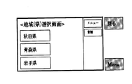
- the region (prefecture) selection screen (G05) is a screen for accepting selection of a region at the prefectural level.
- FIG. 7E as an example, “Akita Prefecture”, “Aomori Prefecture”, and “Iwate Prefecture” are displayed on the region (prefecture) selection screen.
- start (prefecture selection) is selected on the operation explanation screen
- the operation unit 22 of the mobile terminal detects this, and a corresponding operation signal is input to the control unit 21 of the mobile terminal.
- the control unit 21 of the portable terminal receives this operation signal and displays a region (prefecture) selection screen on the display unit 23 of the portable terminal.
- “Akita Prefecture”, “Aomori Prefecture”, and “Iwate Prefecture” are selection regions for transitioning to a screen for accepting a region selection at each municipality level. For example, when “Akita Prefecture” is selected, a transition is made to a district (city) selection screen.
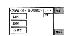
- the district (city) selection screen (G06) is a screen for accepting selection of a region at the municipal level.
- FIG. 7F as an example, “Akita City”, “Kazuno City”, and “Nikaho City” are displayed on the district (city) selection screen.
- the operation unit 22 of the mobile terminal detects this, and a corresponding operation signal is input to the control unit 21 of the mobile terminal.
- the control unit 21 of the mobile terminal receives this operation signal and causes the display unit 23 of the mobile terminal to display a district (city) selection screen corresponding to Akita Prefecture.
- “Akita City”, “Kazuno City”, and “Nikaho City” are selection areas for transition to the user information input screen. For example, when “Akita City” is selected, the screen changes to a user input screen.
- the user input screen (G07) is a screen for accepting user information input.
- items of “sex”, “age”, “walking time”, “journey item”, and “route list” are displayed (see FIG. 7G).
- the operation unit 22 of the mobile terminal detects this, and a corresponding operation signal is input to the control unit 21 of the mobile terminal.
- the control unit 21 of the mobile terminal receives this operation signal and displays a user input screen on the display unit 23 of the mobile terminal.
- Options are provided for “sex”, “age”, “walking time”, and “travel item”, and the user can input user information from the options.
- the route list screen (G08) is a screen for displaying a route search result.
- “eating and walking route”, “historic route”, “wallet friendly route”, “hot spring tour route”, etc. are displayed as search results (see FIG. 7H).
- the operation unit 22 of the mobile terminal detects this, and a corresponding operation signal is input to the control unit 21 of the mobile terminal.
- the control unit 21 of the portable terminal receives this operation signal, transmits the search condition to the content management server 3 via the communication unit 25 of the portable terminal, and receives the search result.
- the control part 21 of a portable terminal displays the route
- “Eat-walking route”, “History enjoying route”, “Wallet-friendly route”, and “Onsen tour route” are selection areas for transition to the route detail screen. For example, when “historic enjoyment route” is selected, a transition is made to the route detail screen.
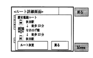
- the route detail screen (C) is a screen that displays the details of the route. On the route details screen, the name of the station on the route, the required time, etc. are displayed (see FIG. 8C).
- the operation unit 22 of the mobile terminal detects this, and a corresponding operation signal is input to the control unit 21 of the mobile terminal.
- the control unit 21 of the mobile terminal displays a route detail screen on the display unit 23 of the mobile terminal.
- Information included in the route details screen may be acquired from the content management server 3 when displaying the route list screen, or may be acquired from the content management server 3 when displaying the route details screen.
- route determination is a selection area for transition to the map screen.
- Return is a selection area for transitioning to the previous screen, that is, the route list screen.
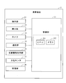
- the map screen (G09) displays a map screen (overhead information) of the selected route.
- “guidance start point”, “guidance end point”, and “balloon” are displayed together with the map (see FIG. 7I).
- the operation unit 22 of the mobile terminal detects this, and a corresponding operation signal is input to the control unit 21 of the mobile terminal.
- the control unit 21 of the mobile terminal transmits the selected route and current location to the content management server 3 via the communication unit 25 of the mobile terminal, and receives map screen data.
- the control part 21 of a portable terminal displays a map screen on the display part 23 of a portable terminal.
- the “guidance start point” is a place where the guidance starts
- the “guidance end point” is a place where the guidance ends.
- “Balloon” is provided in a recommended place, and when “balloon” is selected, an explanation for each place is displayed.
- the “balloon” is color-coded for each genre, for example.
- the genre includes facilities, eating, buying, roads, rivers, mountains, rest areas, toilets, and parking lots. Instead of “balloon”, “pin”, “photo”, “illustration”, “icon” or the like may be used.
- “Menu”, “Language”, “Camera”, “Current location”, and “Display change” are further displayed on the map screen.
- Camera is a selection area for transition to the camera guidance screen.
- Current location is a selection region for transition to a map screen that moves around the current location.
- Display change is a selection area for transition to a balloon display change screen.
- the camera guidance screen (G10) displays view information (real space integrated screen) in which content is superimposed on video captured by the camera 24.
- view information real space integrated screen
- “radar” and “balloon” are displayed on the video imaged by the camera 24 (see FIG. 7J).
- the operation unit 22 of the mobile terminal detects this, and a corresponding operation signal is input to the control unit 23 of the mobile terminal.
- the control unit 21 of the mobile terminal stores the video captured by the camera 24 in the storage unit 28 of the mobile terminal, and superimposes the content acquired from the content management server 3 on the video so that the video captured by the camera 24 is displayed.
- the camera guidance screen on which the content is superimposed is displayed on the display unit 23 of the mobile terminal.
- the circle at the bottom right of the screen is a radar image view (hereinafter referred to as radar display), and this radar display is color-coded according to the type of tourist information around you (mobile terminal user). Displayed.
- radar display transition to the radar range change screen is possible.
- the arrow at the bottom center of the screen indicates the direction to the next destination, and the distance is displayed next to the arrow. The distance displayed with this arrow indicates the distance to the next destination.
- “balloon” is displayed on the camera guidance screen, and the distance to the location corresponding to the balloon is displayed below “balloon”.
- “menu”, “language”, and “display change” similar to those on the map screen are displayed on the camera guidance screen.
- a “map” is displayed on the camera guidance screen, and this “map” is a selection area for transition to the map screen.
- the menu screen (A) is a screen that displays a menu of the navigation application. On the menu screen, “go to user information input screen”, “go to route list screen”, and “end navigation application” are displayed (see FIG. 8A).
- “Menu” is selected on the application selection screen, operation explanation screen, region (prefecture) selection screen, district (city) selection screen, user input screen, route list screen, map screen, and camera guidance screen
- the mobile terminal The operation unit 22 detects this, and a corresponding operation signal is input to the control unit 21 of the portable terminal.
- the control unit 21 of the mobile terminal receives this operation signal and displays a menu screen on the display unit 23 of the mobile terminal.
- “To user information input screen” is a selection area for transition to the user information input screen.
- “To route list screen” is a selection area for transition to the route list screen.
- “End of navigation application” is a selection area for transition to the application selection screen.
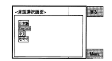
- the language selection screen (B) is a screen that accepts selection of text used in the navigation application.
- “Japanese”, “English”, “Chinese”, and “Korean” are displayed (see FIG. 8B).
- “Menu” is selected on the application selection screen, operation explanation screen, region (prefecture) selection screen, district (city) selection screen, user input screen, route list screen, map screen, and camera guidance screen
- the mobile terminal The operation unit 22 detects this, and a corresponding operation signal is input to the control unit 21 of the portable terminal.
- the control unit 21 of the mobile terminal displays a language selection screen on the display unit 23 of the mobile terminal.
- “Japanese”, “English”, “Chinese”, or “Korean” is selected on the language selection screen, the language used by the navigation application is changed.
- the language displayed on the language selection screen is not limited to the above.
- the balloon display change screen (D) is a screen for changing settings of balloon display displayed on the map screen and the camera guide screen.
- the balloon display change screen check the corresponding genres of balloons as “facility”, “eat”, “buy”, “road / river”, “mountain”, “rest area / toilet”, “parking lot” and each.
- a box is displayed (see FIG. 8D).
- the operation unit 22 of the mobile terminal detects this, and a corresponding operation signal is input to the control unit 21 of the mobile terminal.
- the control unit 21 of the mobile terminal displays a language selection screen on the display unit 23 of the mobile terminal.
- the information detail screen (E) displays detailed information on the location corresponding to the balloon displayed on the map screen and the camera guidance screen.
- On the information detail screen for example, recommended products and images of shops are displayed (see FIG. 8E).
- the operation unit 22 of the mobile terminal detects this, and a corresponding operation signal is input to the control unit 21 of the mobile terminal.
- the control unit 21 of the mobile terminal displays detailed information corresponding to the selected “balloon” on the display unit 23 of the mobile terminal.
- the screen transitions to the transition source screen (map screen or camera guidance screen).
- the radar range change screen (F) is a screen for changing the radar display range displayed on the camera guidance screen.
- On the radar range change screen “50 m”, “100 m”, “200 m”, “500 m”, “1 km”, “2 km”, and “3 km” are displayed (see FIG. 8F).
- the operation unit 22 of the mobile terminal detects this, and a corresponding operation signal is input to the control unit 21 of the mobile terminal.
- the control unit 21 of the portable terminal receives this operation signal and displays a radar range change screen.
- the screen changes to the camera guidance screen.
- the content management server 3 performs content management, route management, content route search, and the like.
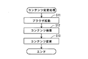
- FIG. 9 shows a content registration processing flow.
- the control unit 31 of the server activates the browser based on an instruction from the administrator or the user.
- the address and password of the management screen are input via the operation unit 32 of the server, a corresponding operation signal is input to the control unit 31 of the server.
- the server control unit 31 causes the display unit 33 of the server to display a content management screen.
- FIG. 11A shows a content management screen. On the content management screen, a “content information” tab and a “route information” tab are displayed. In FIG. 11A, “content information” is selected, and “content registration” and “content search” are displayed in the content information.
- the browser When the browser is activated, the process proceeds to step S02.
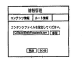
- step S02 the server control unit 31 registers content. Specifically, the control unit 31 of the server displays a registration screen on the display unit 33 of the server and accepts content registration.
- FIG. 11B shows a content registration screen.
- a CSV file is selected as an example. “Registration” and “Cancel” are displayed on the registration screen, and when “Register” is selected, the selected file is registered. That is, when new content is input via the operation unit 32 of the server, the control unit 31 of the server registers the input content in the database of the storage unit 35 of the server. Thus, the content registration process ends.
- Step S11 is the same as step S01, and the server control unit 31 activates the browser based on an instruction from the administrator or user, and causes the display unit 33 of the server to display a content management screen.
- the browser is activated, the process proceeds to step S12.
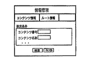
- step S12 the control unit 31 of the server searches for content. Specifically, the control unit 31 of the server displays a search screen on the display unit 33 of the server and accepts content search conditions.
- FIG. 11C shows a content search screen. On the content search screen, it is possible to input a content number and a content name. After inputting these, when “Search” is selected, the search is executed based on the input content number and content name. That is, when a content number, content name, or the like is input via the operation unit 32 of the server, the control unit 31 of the server accesses the database of the storage unit 35 of the server and searches for the content. When the content is retrieved, the process proceeds to step S13.
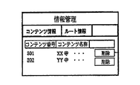
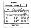
- step S13 the control unit 31 of the server changes the content. Specifically, the control unit 31 of the server first displays a search result screen on the display unit 33 of the server.
- FIG. 11D shows a content search result screen. A list of searched contents is displayed on the contents search result screen. Further, “delete” is displayed beside each content, and when “delete” is selected, the content is deleted. Next, when the content is selected from the content search result list, the server control unit 31 displays the selected content change screen on the server display unit 33.
- FIG. 11E shows a content change screen (basic information). On the content change screen (basic information), the content number and the content name are displayed and can be changed.
- the server control unit 31 accesses the database in the storage unit 35 of the server and updates the database.
- “additional information” is selected on the content change screen (basic information)
- the server control unit 31 causes the display unit 33 of the server to display the content change screen (additional information).
- FIG. 11F shows a content change screen (additional information).
- additional information that is detailed content information (in FIG. 11F, entrance fee, parking lot presence / absence) is displayed, and these can be changed.
- the server control unit 31 accesses the database in the storage unit 35 of the server and updates the database.
- the content change process ends.
- Route management includes new registration of route information (hereinafter referred to as route registration processing) and change of an already registered route (hereinafter referred to as route change processing).
- route registration processing new registration of route information
- route change processing change of an already registered route
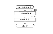
- FIG. 12 shows a route registration process flow.
- the control unit 31 of the content management server 3 (hereinafter also simply referred to as a server) starts a browser based on an instruction from an administrator or a user, and causes the display unit 33 of the server to display a content management screen.
- FIG. 14A shows a route management screen.
- a “content information” tab and a “route information” tab are displayed.
- “route information” is selected, and “route registration” and “route search” are displayed in the route information.
- step S22 the control unit 31 of the server registers a route. Specifically, first, the control unit 31 of the server displays a registration screen (basic information) on the display unit 33 of the server, and accepts content registration.
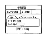
- FIG. 14B shows a route registration screen (basic information). On the route registration screen (basic information), a route number and a route name are displayed, and these can be registered.
- the server control unit 31 accesses the database in the storage unit 35 of the server and registers the route. Further, when “content list” is selected on the route registration screen (basic information), the control unit 31 of the server causes the display unit 33 of the server to display the route registration screen (content list).
- FIG. 14B shows a route registration screen (basic information).
- FIG. 14C shows a route registration screen (content list).
- content constituting the route can be registered, and the registered content is sequentially displayed as a list.
- the control unit 31 of the server accesses the database in the storage unit 35 of the server and registers the content constituting the route in the database.
- “map” is displayed.
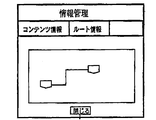
- FIG. 14D shows a route confirmation screen.
- the route confirmation screen the route and the contents constituting the route are displayed. “Close” is displayed on the route confirmation screen, and when “Close” is selected, the screen transits to the route registration screen (content list). This completes the route registration process.
- Step S31 is the same as step S21, and the server control unit 31 activates the browser based on an instruction from the administrator or the user, and displays a route management screen on the server display unit 33 (see FIG. 14A).
- the browser is activated, the process proceeds to step S32.
- step S32 the control unit 31 of the server searches for content. Specifically, the control unit 31 of the server displays a search screen on the display unit 33 of the server and accepts content search conditions.
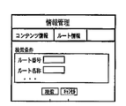
- FIG. 14E shows a route search screen. On the route search screen, it is possible to input a route number and a route name. When these items are input and “Search” is selected, the search is executed based on the input route number and route name. That is, when a route number, a route name, or the like is input via the server operation unit 32, the server control unit 31 accesses the database in the server storage unit 35 and searches for a route. When the route is searched, the process proceeds to step S33.
- step S33 the server control unit 31 changes the route. Specifically, the control unit 31 of the server first displays a route search result list screen on the display unit 33 of the server.
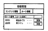
- FIG. 14F shows a route search result list screen.
- the route search result list screen displays a list of searched routes. Further, “delete” is displayed beside each route, and the content is deleted when “delete” is selected.
- the server control unit 31 causes the server display unit 33 to display a screen for changing the selected route.
- FIG. 14G shows a route change screen (basic information). On the route change screen (basic information), a route number and a route name are displayed, and these can be changed.
- the server control unit 31 accesses the database in the storage unit 35 of the server and updates the database. Further, when “content list” is selected on the route change screen (basic information), the server control unit 31 displays the route change screen (content list) on the server display unit 33 (see FIG. 14C). On the route registration screen (content list), the content constituting the route can be changed, and the changed content is sequentially displayed as a list.
- the server control unit 31 accesses the database of the storage unit 35 of the server and changes the content configuring the route.
- “map” is displayed. By selecting “Map”, the screen transits to the route confirmation screen (see FIG. 14D). Thus, the route change process ends.
- FIG. 15 shows a route content search processing flow.
- the control unit 31 of the server acquires a search condition. Specifically, the control unit 31 of the server transmits the mobile terminal 2 identification information, current location, search conditions (region (prefecture, city), gender, age, walking time, travel purpose, radar, and the like. Range).
- search conditions region (prefecture, city), gender, age, walking time, travel purpose, radar, and the like. Range).
- step S42 the control unit 31 of the server searches for route content. Specifically, the control unit 31 of the server accesses the database and extracts route content from the database based on the identification information of the mobile terminal, the current location, the direction, the search condition, and the like. When extracting the content, the control unit 31 of the server compares the current location with the radar range, and extracts the content within the radar range set with the current location as a reference. When the root content is retrieved, the process proceeds to step S43.
- step S43 the control unit 31 of the server provides the search result to the portable terminal 2. That is, the control unit 31 of the server transmits the route content extracted from the database to the mobile terminal 2. Thus, the search for the root content is completed.
- Camera guidance screen display processing Next, details of the display process of the camera guidance screen will be described.
- the camera guidance screen display process described below it is possible to display content at an appropriate position more easily than in the past.
- FIG. 16A shows a display processing flow of the camera guidance screen.
- the control unit 21 of the mobile terminal acquires video and content.
- the video is shot by the camera 24 and stored in the storage unit 28 of the portable terminal, and the content is provided from the content management server 3 and stored in the storage unit 28 of the portable terminal.
- the control part 21 of a portable terminal accesses the memory
- the content server 3 sends the content to be displayed on the display unit 23 to the mobile terminal 2 based on the position information of the mobile terminal 2, the camera direction (horizontal direction), and the camera angle (vertical direction).
- the contents to be displayed can include contents in a wider range than the field of view of the camera 24 as well as contents within the field of view of the camera 24.
- the control unit 21 of the portable terminal acquires content transmitted from the content server 3 via the communication unit 25.
- the control unit 21 of the mobile terminal determines from the horizontal view angle and the vertical view angle of the camera 24.
- Content that falls within the field of view of the camera 24 is extracted. Note that only content within a predetermined distance from the camera 24 may be extracted from the content that falls within the viewing angle of the camera 24.
- the predetermined distance can be preset such as 1 km or 5 km.
- step S52 the control unit 21 of the mobile terminal performs temporary positioning of the content.
- the control unit 21 of the mobile terminal performs a perspective process on the content acquired in a rectangular plane including the center point with the height of the mobile terminal 2 as the center point in the coordinate space with the current location of the mobile terminal 2 as the origin. Temporarily determine the display position.
- the height of the portable terminal 2 can be set to 1.5 m from the ground surface, for example. That is, a value obtained by adding 1.5 m to the altitude at the position of the mobile terminal is set as the height of the mobile terminal 2.
- the temporary positioning is performed in consideration of the horizontal field of view of the camera 24, the vertical viewing angle, the image size, and the like.
- the horizontal position on the screen is determined based on the latitude and longitude information, and the vertical position on the screen is determined according to the distance from the origin, which is the current location of the mobile terminal 2.
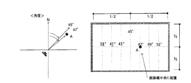
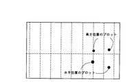
- FIG. 16B shows an image for determining an angle when “target point” is displayed.
- the left diagram is a plan view showing the positional relationship between the direction of the camera 24 and “target point A”, and the right diagram overlays “target point A” on the video imaged by the camera 24. Show the image.
- the “target point” is, for example, a base point of a balloon or a balloon that displays content, and corresponds to the position of the target object that displays the content.
- the direction of the optical axis of the camera 24 is set as a vertical reference line passing through the center in the horizontal direction of the screen.
- auxiliary vertical reference lines parallel to the vertical reference lines are set at predetermined intervals (in steps of 2 degrees in FIG. 16B).
- the vertical reference line and the auxiliary vertical reference line correspond to the azimuth reference line of the present invention.
- “Target point A” is plotted on the auxiliary vertical reference line on the northeast side 47 ° and on the horizontal reference line.
- the horizontal reference line is a horizontal reference line set at the center in the vertical direction, and corresponds to the distance reference line of the present invention.
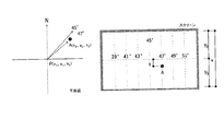
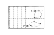
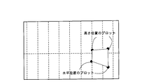
- FIGS. 16C and 16D the distance of the “target point A”, in other words, the distance in the vertical direction from the horizontal reference line is determined.
- the distance of the “target point A” can be represented by a distance y from the horizontal reference line, and this y is calculated based on Equation 1.
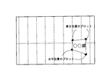
- FIG. 16C shows an image for determining the distance when displaying the “target point”.
- FIG. 16D is a cross-sectional view showing the relationship between the camera 24 and the point A.
- the left diagram is a plan view showing the positional relationship between the orientation of the camera 24 and “target point A”, and the right diagram overlays “target point A” on the video imaged by the camera 24. Show the image.
- the angle of the camera 24 (vertical direction) is assumed to be as follows, assuming that the optical axis is parallel to the ground.
- Equation 2 the visual field vertical limit length V on the vertical plane passing through the target point is expressed by Equation 2
- Equation 3 the altitude difference Y between the own point and the target point is expressed by Equation 3.
- Equation 5 the horizontal distance from one's own point to the target point is expressed by Equation 5.
- Equation 5 the relational expression 1 is established, and the distance in the vertical direction from the screen center line can be calculated.
- the angle and distance of “target point A” are determined.
- target points that is, all the contents to be displayed are processed, and the angles and distances of all the contents are determined, the temporary positioning of the contents is completed.
- the target point determination process has been described as provisional positioning of the display position of the content. However, for example, when correction described later is not performed, the above-described target point determination processing can be used as positioning processing for content display positions.
- the process proceeds to step S53.
- step S53 the control unit 21 of the mobile terminal performs image analysis for correction. Specifically, the control unit 21 of the mobile terminal analyzes the intensity (Intensity) of each pixel of the image and calculates a ridgeline, a road boundary line, and a horizontal line.
- FIG. 17B shows a state in which the ridgeline, the road boundary line, and the horizontal line are calculated by analyzing the intensity (Intensity) of each pixel of the image.
- “Line 1” indicates a ridgeline of a building, a tree, or a mountain.
- “Line 2” indicates a road boundary line.
- “Line 3” indicates a horizontal line passing through the focal points of the two road boundary lines.
- step S54 the control unit 21 of the mobile terminal corrects the display position of the content.
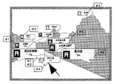
- FIG. 17C shows how the content display position is corrected.
- content other than the content related to the road among the content existing inside the road boundary line (line 2) is moved to the outside of the road boundary line.
- the content corrected by this rule is indicated by “# 1” in FIG. 17C.
- the vertical position on the screen the content closest to the origin is arranged in the vicinity of the horizontal line, and the other contents are sequentially arranged in the back.
- the content corrected by this rule is indicated by “# 2” in FIG. 17C.
- content related to mountains and trees is arranged above the ridgeline.
- the content corrected by this rule is indicated by “# 3” in FIG. 17C.
- the content related to the road is arranged below the ridgeline.
- the content corrected by this rule is indicated by “# 4” in FIG. 17C.
- Other contents are arranged between the ridgeline and the road boundary line.
- the content corrected by this rule is indicated by “# 5” in FIG. 17C.
- step S55 the control unit 21 of the mobile terminal displays a camera guidance screen on the display unit 23 of the mobile terminal.
- FIG. 17D shows a display example of the camera guidance screen.
- the radar displayed at the lower left of the screen is separately created from the current location, direction, and radar range, and is drawn on another transparent image layer.
- the image layer including the content and the image layer including the radar are superimposed on the video captured by the camera 24.
- a camera guidance screen is generated.
- a camera guidance screen is generated in real time.
- the temporary positioning of the content may be, for example, dividing the video into three parts at the upper part, the central part, and the lower part, and assigning the contents to each region.
- content relating to mountains may be assigned to the upper part
- content relating to rivers and roads may be assigned to the lower part
- contents relating to others such as buildings
- a navigation service using AR technology can be provided. Since the route and content managed by the content management server 3 can be easily registered or changed, route guidance based on the latest and abundant information is possible. Further, the mobile terminal 2 can guide the route by using both the map screen and the camera guidance screen. Further, on the camera guidance screen, the “road” that is most important when guiding the route can be displayed reliably, and the user can be guided with a more easily displayed display.
- the degree of freedom of content display is limited, and only balloons, pins, photos, icons, etc. can be displayed.
- the process for determining the angle and position of the target point described in the first embodiment not only the horizontal position but also the vertical position can be accurately displayed on the screen. Accordingly, it is possible to display an object having a high degree of design freedom, such as an object (target object) that matches the shape of the building.
- FIGS. 18A to 18E show a procedure for displaying content having four target points on an object.
- the content server previously stores the longitude, latitude, and height of the target point (corresponding to the corner of the target object) for specifying the shape of one target object in advance. Must be stored.
- four target points will be described as an example.
- a three-dimensional display is also possible.
- a signboard is displayed will be described as an example.
- the control unit 21 of the mobile terminal specifies (plots) the target point of the horizontal position. That is, the target points corresponding to both ends of the lower side of the signboard are specified according to the angle and distance calculation process of the target point A described in the temporary positioning process of the first embodiment.
- the control unit 21 of the mobile terminal specifies the target point of the height position. That is, the target points corresponding to both ends of the upper side of the signboard are specified according to the calculation process of the angle and distance of the target point A described in the temporary positioning process of the first embodiment.
- the control unit 21 of the mobile terminal connects the four specified target points and specifies the outline.
- FIG. 18A the control unit 21 of the mobile terminal specifies (plots) the target point of the horizontal position. That is, the target points corresponding to both ends of the lower side of the signboard are specified according to the angle and distance calculation process of the target point A described in the temporary positioning process of the first embodiment.
- the control unit 21 of the mobile terminal specifies an area (inside the outline) determined by connecting the four target points as a plane. Furthermore, as illustrated in FIG. 18E, the control unit 21 of the mobile terminal sets text on the specified surface. Note that a photo, an illustration, or the like may be used instead of the text. Moreover, you may set a hyperlink. Further, the control unit 21 of the mobile terminal may set the texture, brightness / brightness, color, gradation, and the like of the surface surrounded by connecting the plots.
Landscapes
- Engineering & Computer Science (AREA)
- Physics & Mathematics (AREA)
- General Physics & Mathematics (AREA)
- Theoretical Computer Science (AREA)
- Multimedia (AREA)
- Computer Vision & Pattern Recognition (AREA)
- Processing Or Creating Images (AREA)
- User Interface Of Digital Computer (AREA)
- Navigation (AREA)
Abstract
Priority Applications (2)
| Application Number | Priority Date | Filing Date | Title |
|---|---|---|---|
| JP2013505679A JP5728775B2 (ja) | 2011-03-22 | 2011-03-22 | 情報処理装置、及び情報処理方法 |
| PCT/JP2011/056784 WO2012127605A1 (fr) | 2011-03-22 | 2011-03-22 | Dispositif de traitement d'informations et procédé de traitement d'informations |
Applications Claiming Priority (1)
| Application Number | Priority Date | Filing Date | Title |
|---|---|---|---|
| PCT/JP2011/056784 WO2012127605A1 (fr) | 2011-03-22 | 2011-03-22 | Dispositif de traitement d'informations et procédé de traitement d'informations |
Publications (1)
| Publication Number | Publication Date |
|---|---|
| WO2012127605A1 true WO2012127605A1 (fr) | 2012-09-27 |
Family
ID=46878801
Family Applications (1)
| Application Number | Title | Priority Date | Filing Date |
|---|---|---|---|
| PCT/JP2011/056784 Ceased WO2012127605A1 (fr) | 2011-03-22 | 2011-03-22 | Dispositif de traitement d'informations et procédé de traitement d'informations |
Country Status (2)
| Country | Link |
|---|---|
| JP (1) | JP5728775B2 (fr) |
| WO (1) | WO2012127605A1 (fr) |
Cited By (17)
| Publication number | Priority date | Publication date | Assignee | Title |
|---|---|---|---|---|
| GB2506338A (en) * | 2012-07-30 | 2014-04-02 | Sony Comp Entertainment Europe | A method of localisation and mapping |
| JPWO2013088557A1 (ja) * | 2011-12-15 | 2015-04-27 | パイオニア株式会社 | 表示装置及び表示方法 |
| WO2016031358A1 (fr) * | 2014-08-27 | 2016-03-03 | ソニー株式会社 | Dispositif de commande d'affichage, procédé de commande d'affichage et programme |
| JP2016136376A (ja) * | 2015-01-14 | 2016-07-28 | 株式会社リコー | 情報処理装置、情報処理方法及びプログラム |
| JP2017505933A (ja) * | 2013-11-26 | 2017-02-23 | シェフィ,ヨァヴ | 実在の物体上に固定された仮想画像を生成する方法及びシステム |
| JP2017126142A (ja) * | 2016-01-13 | 2017-07-20 | 株式会社ぐるなび | 情報処理装置、情報処理方法及びプログラム |
| JP2018012407A (ja) * | 2016-07-20 | 2018-01-25 | 株式会社日立製作所 | 鉄道の支障範囲可視化システムおよび管理サーバ |
| JP2018049624A (ja) * | 2016-09-23 | 2018-03-29 | 雨暹 李 | ロケーションベース空間オブジェクト遠隔管理方法及びロケーションベース空間オブジェクト遠隔管理システム |
| JP2018170026A (ja) * | 2018-06-14 | 2018-11-01 | 株式会社東芝 | アプリケーション指定に対応するユニット |
| US10192332B2 (en) | 2015-03-26 | 2019-01-29 | Fujitsu Limited | Display control method and information processing apparatus |
| JP2019023875A (ja) * | 2018-09-03 | 2019-02-14 | 株式会社東芝 | ユニットの制御方法 |
| JP2019023874A (ja) * | 2018-09-03 | 2019-02-14 | 株式会社東芝 | クライアントシステム |
| CN112541467A (zh) * | 2020-12-21 | 2021-03-23 | 杭州光粒科技有限公司 | 信息显示方法、装置及设备、存储介质 |
| JP2022179480A (ja) * | 2016-09-22 | 2022-12-02 | ナビティア・エルエルシー | 拡張現実アーキテクチャにおける改善されたデータ統合のためのシステムおよび方法 |
| WO2023276141A1 (fr) * | 2021-07-02 | 2023-01-05 | Mitsubishi Electric Corporation | Système et procédé de fourniture |
| WO2023026546A1 (fr) * | 2021-08-25 | 2023-03-02 | ソニーセミコンダクタソリューションズ株式会社 | Dispositif de traitement d'informations |
| US11936744B2 (en) | 2015-04-23 | 2024-03-19 | Kabushiki Kaisha Toshiba | Client system, combination client system and server client system |
Families Citing this family (1)
| Publication number | Priority date | Publication date | Assignee | Title |
|---|---|---|---|---|
| IT201700058961A1 (it) | 2017-05-30 | 2018-11-30 | Artglass S R L | Metodo e sistema di fruizione di un contenuto editoriale in un sito preferibilmente culturale o artistico o paesaggistico o naturalistico o fieristico o espositivo |
Citations (2)
| Publication number | Priority date | Publication date | Assignee | Title |
|---|---|---|---|---|
| JP2005289264A (ja) * | 2004-04-01 | 2005-10-20 | Furuno Electric Co Ltd | 船舶航行支援装置 |
| JP2010244575A (ja) * | 2004-08-19 | 2010-10-28 | Sony Computer Entertainment Inc | ポータブル拡張現実感デバイスおよびその方法 |
-
2011
- 2011-03-22 JP JP2013505679A patent/JP5728775B2/ja active Active
- 2011-03-22 WO PCT/JP2011/056784 patent/WO2012127605A1/fr not_active Ceased
Patent Citations (2)
| Publication number | Priority date | Publication date | Assignee | Title |
|---|---|---|---|---|
| JP2005289264A (ja) * | 2004-04-01 | 2005-10-20 | Furuno Electric Co Ltd | 船舶航行支援装置 |
| JP2010244575A (ja) * | 2004-08-19 | 2010-10-28 | Sony Computer Entertainment Inc | ポータブル拡張現実感デバイスおよびその方法 |
Non-Patent Citations (1)
| Title |
|---|
| TARO ODAJIMA ET AL.: "An Outdoor Wearable Augmented Reality System Using a GPS", FIT2002, FORUM ON INFORMATION TECHNOLOGY IPPAN KOEN RONBUNSHU, vol. 3, 13 September 2002 (2002-09-13), pages 187 - 188 * |
Cited By (28)
| Publication number | Priority date | Publication date | Assignee | Title |
|---|---|---|---|---|
| JPWO2013088557A1 (ja) * | 2011-12-15 | 2015-04-27 | パイオニア株式会社 | 表示装置及び表示方法 |
| US9704244B2 (en) | 2012-07-30 | 2017-07-11 | Sony Computer Entertainment Europe Limited | Localisation and mapping |
| US9824450B2 (en) | 2012-07-30 | 2017-11-21 | Sony Interactive Entertainment Europe Limited | Localisation and mapping |
| GB2506338A (en) * | 2012-07-30 | 2014-04-02 | Sony Comp Entertainment Europe | A method of localisation and mapping |
| US9415310B2 (en) | 2012-07-30 | 2016-08-16 | Sony Computer Entertainment Europe Limited | Localisation and mapping |
| US9679381B2 (en) | 2012-07-30 | 2017-06-13 | Sony Computer Entertainment Europe Limited | Localisation and mapping |
| US10657663B2 (en) | 2012-07-30 | 2020-05-19 | Sony Interactive Entertainment Europe Limited | Localisation and mapping |
| US9779509B2 (en) | 2012-07-30 | 2017-10-03 | Sony Interactive Entertainment Europe Limited | Localisation and mapping |
| JP2017505933A (ja) * | 2013-11-26 | 2017-02-23 | シェフィ,ヨァヴ | 実在の物体上に固定された仮想画像を生成する方法及びシステム |
| WO2016031358A1 (fr) * | 2014-08-27 | 2016-03-03 | ソニー株式会社 | Dispositif de commande d'affichage, procédé de commande d'affichage et programme |
| JPWO2016031358A1 (ja) * | 2014-08-27 | 2017-06-08 | ソニー株式会社 | 表示制御装置、表示制御方法およびプログラム |
| US10796669B2 (en) | 2014-08-27 | 2020-10-06 | Sony Corporation | Method and apparatus to control an augmented reality head-mounted display |
| JP2016136376A (ja) * | 2015-01-14 | 2016-07-28 | 株式会社リコー | 情報処理装置、情報処理方法及びプログラム |
| US10192332B2 (en) | 2015-03-26 | 2019-01-29 | Fujitsu Limited | Display control method and information processing apparatus |
| US11936744B2 (en) | 2015-04-23 | 2024-03-19 | Kabushiki Kaisha Toshiba | Client system, combination client system and server client system |
| JP2017126142A (ja) * | 2016-01-13 | 2017-07-20 | 株式会社ぐるなび | 情報処理装置、情報処理方法及びプログラム |
| JP2018012407A (ja) * | 2016-07-20 | 2018-01-25 | 株式会社日立製作所 | 鉄道の支障範囲可視化システムおよび管理サーバ |
| JP2022179480A (ja) * | 2016-09-22 | 2022-12-02 | ナビティア・エルエルシー | 拡張現実アーキテクチャにおける改善されたデータ統合のためのシステムおよび方法 |
| JP7475401B2 (ja) | 2016-09-22 | 2024-04-26 | ナビティア・エルエルシー | 拡張現実アーキテクチャにおける改善されたデータ統合のためのシステムおよび方法 |
| JP2018049624A (ja) * | 2016-09-23 | 2018-03-29 | 雨暹 李 | ロケーションベース空間オブジェクト遠隔管理方法及びロケーションベース空間オブジェクト遠隔管理システム |
| JP2018170026A (ja) * | 2018-06-14 | 2018-11-01 | 株式会社東芝 | アプリケーション指定に対応するユニット |
| JP2019023874A (ja) * | 2018-09-03 | 2019-02-14 | 株式会社東芝 | クライアントシステム |
| JP2019023875A (ja) * | 2018-09-03 | 2019-02-14 | 株式会社東芝 | ユニットの制御方法 |
| CN112541467A (zh) * | 2020-12-21 | 2021-03-23 | 杭州光粒科技有限公司 | 信息显示方法、装置及设备、存储介质 |
| WO2023276141A1 (fr) * | 2021-07-02 | 2023-01-05 | Mitsubishi Electric Corporation | Système et procédé de fourniture |
| JP2024502368A (ja) * | 2021-07-02 | 2024-01-18 | 三菱電機株式会社 | 提供システム、および、提供方法 |
| JP7499974B2 (ja) | 2021-07-02 | 2024-06-14 | 三菱電機株式会社 | 提供システム、および、提供方法 |
| WO2023026546A1 (fr) * | 2021-08-25 | 2023-03-02 | ソニーセミコンダクタソリューションズ株式会社 | Dispositif de traitement d'informations |
Also Published As
| Publication number | Publication date |
|---|---|
| JPWO2012127605A1 (ja) | 2014-07-24 |
| JP5728775B2 (ja) | 2015-06-03 |
Similar Documents
| Publication | Publication Date | Title |
|---|---|---|
| JP5728775B2 (ja) | 情報処理装置、及び情報処理方法 | |
| JP5383930B2 (ja) | 端末装置の視野に含まれている客体に関する情報を提供するための方法、端末装置及びコンピュータ読み取り可能な記録媒体 | |
| CN105659304B (zh) | 车辆、导航系统及生成并递送导航信息的方法 | |
| US8467810B2 (en) | Method and system for reporting errors in a geographic database | |
| US10309797B2 (en) | User interface for displaying navigation information in a small display | |
| US9116011B2 (en) | Three dimensional routing | |
| US7088389B2 (en) | System for displaying information in specific region | |
| US20210025729A1 (en) | Street-Level Guidance Via Route Path | |
| US20130162665A1 (en) | Image view in mapping | |
| US10445772B1 (en) | Label placement based on objects in photographic images | |
| US20110137561A1 (en) | Method and apparatus for measuring geographic coordinates of a point of interest in an image | |
| EP2302531A1 (fr) | Procédé pour la fourniture d'un affichage à réalité améliorée dans un dispositif mobile | |
| US20190212163A1 (en) | Route planning method and apparatus, computer storage medium, terminal | |
| US20140002440A1 (en) | On Demand Image Overlay | |
| JP2010118019A (ja) | 端末装置、配信装置、端末装置の制御方法、配信装置の制御方法、制御プログラムおよび記録媒体 | |
| US20220076469A1 (en) | Information display device and information display program | |
| US20170039450A1 (en) | Identifying Entities to be Investigated Using Storefront Recognition | |
| US20150135114A1 (en) | Distinguishable geographic area presentation | |
| JP5877394B2 (ja) | コンテンツ提供システム、サーバ、及びコンテンツ提供方法 | |
| JP6384898B2 (ja) | 経路案内システム、方法及びプログラム | |
| KR102273919B1 (ko) | 사용자 주변 포커싱을 통한 지역 정보 자동 인식 장치 및 방법 | |
| US8869058B1 (en) | Interface elements for specifying pose information for photographs in an online map system | |
| RU2375756C2 (ru) | Навигационное устройство с информацией, получаемой от камеры | |
| KR102200464B1 (ko) | 지점 안내 서비스 제공 시스템 및 방법, 그리고 이를 위한 장치 및 컴퓨터 프로그램이 기록된 기록매체 | |
| JP6019680B2 (ja) | 表示装置、表示方法、及び、表示プログラム |
Legal Events
| Date | Code | Title | Description |
|---|---|---|---|
| WWE | Wipo information: entry into national phase |
Ref document number: 7723/CHENP/2012 Country of ref document: IN |
|
| 121 | Ep: the epo has been informed by wipo that ep was designated in this application |
Ref document number: 11861572 Country of ref document: EP Kind code of ref document: A1 |
|
| NENP | Non-entry into the national phase |
Ref country code: DE |
|
| ENP | Entry into the national phase |
Ref document number: 2013505679 Country of ref document: JP Kind code of ref document: A |
|
| 122 | Ep: pct application non-entry in european phase |
Ref document number: 11861572 Country of ref document: EP Kind code of ref document: A1 |