WO2012127635A1 - Appareil de traitement d'informations, programme d'évaluation d'application de révision et procédé d'évaluation d'application de révision - Google Patents
Appareil de traitement d'informations, programme d'évaluation d'application de révision et procédé d'évaluation d'application de révision Download PDFInfo
- Publication number
- WO2012127635A1 WO2012127635A1 PCT/JP2011/056853 JP2011056853W WO2012127635A1 WO 2012127635 A1 WO2012127635 A1 WO 2012127635A1 JP 2011056853 W JP2011056853 W JP 2011056853W WO 2012127635 A1 WO2012127635 A1 WO 2012127635A1
- Authority
- WO
- WIPO (PCT)
- Prior art keywords
- patch
- data
- program
- correction
- counter
- Prior art date
- Legal status (The legal status is an assumption and is not a legal conclusion. Google has not performed a legal analysis and makes no representation as to the accuracy of the status listed.)
- Ceased
Links
Images




Classifications
-
- G—PHYSICS
- G06—COMPUTING OR CALCULATING; COUNTING
- G06F—ELECTRIC DIGITAL DATA PROCESSING
- G06F8/00—Arrangements for software engineering
- G06F8/60—Software deployment
- G06F8/65—Updates
Definitions
- the present invention relates to an information processing apparatus and the like.
- the conventional technology for applying a patch has a problem that it is difficult to determine whether to apply a patch.
- a skill when extracting a patch to be applied, if a skill is high, a patch that is not excessive or insufficient can be extracted. However, if a skill is low, it may be impossible to determine whether to apply a patch. Even if the skill is high, it is difficult to extract a patch that is not excessive or insufficient in consideration of the combination of patches.
- the number of times of running is counted regardless of which part of the program has been operated, so that it is necessary to apply a patch in its own system by this count. It is difficult to determine whether or not.
- the disclosed technology aims to provide an information processing apparatus and the like that can appropriately determine whether or not to apply a patch.
- the information processing apparatus disclosed in the present application includes a provisional correction program that incorporates a process for counting the number of times the correction part is executed when the correction part is executed when the program being operated is corrected.
- a provisional correction program that incorporates a process for counting the number of times the correction part is executed when the correction part is executed when the program being operated is corrected.
- FIG. 1 is a functional block diagram illustrating a configuration of a system that performs patch application determination according to the embodiment.
- FIG. 2 is a diagram for explaining a specific example of patch creation by the patch creation unit.
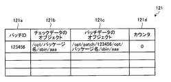
- FIG. 3 is a diagram illustrating an example of a data structure of the counter DB according to the embodiment.
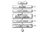
- FIG. 4 is a flowchart illustrating a procedure for creating a patch according to the embodiment.
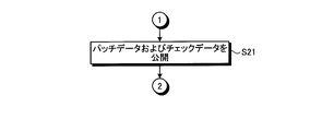
- FIG. 5 is a flowchart illustrating the procedure of patch release according to the embodiment.
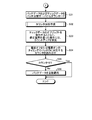
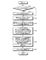
- FIG. 6 is a flowchart illustrating a procedure of patch application determination according to the embodiment.
- FIG. 7 is a flowchart illustrating the procedure for creating the counter DB according to the embodiment.
- FIG. 8 is a flowchart illustrating the procedure of the counter process according to the embodiment.
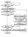
- FIG. 9 is a flowchart illustrating a procedure of applying patch data according to the embodiment.
- FIG. 10 is a diagram illustrating a specific example of the contents of patch data.
- FIG. 11 is a diagram for explaining the state of the counter DB.
- FIG. 12 is a diagram for explaining the state of the counter DB when there are two objects that are corrected for one patch ID.
- FIG. 13 is a diagram illustrating a computer that executes a patch application determination program.
- FIG. 1 is a functional block diagram illustrating a configuration of a system that performs patch application determination according to the embodiment.
- the computer system 1 includes an information processing apparatus 10, a network 20, a patch release server 30, and a patch creation server 40.
- the patch creation server 40 is a server that creates patches. That is, the patch creation server 40 creates patch data in which a failure location of the program is corrected when a failure occurs in any location of the program being operated. Further, the patch creation server 40 creates check data for determining whether or not to apply the patch data in the information processing apparatus 10 to be described later, which is the side to which the patch is applied.
- the check data refers to data in which a counter process is incorporated at a patch data correction location. This counter process increases a count corresponding to a patch ID (identification) given as identification information of patch data when called.
- the counter process increases the count corresponding to the patch ID of the patch data delivered as a parameter.
- the count processing is, for example, partized in a library created in advance.
- the patch creation server 40 includes a control unit 41 and a storage unit 42.
- the control unit 41 includes a patch creation unit 411.
- the storage unit 42 includes source data 421 before correction and source data 422 after correction.
- the pre-correction source data 421 indicates a source file of an operating program.
- the corrected source data 422 indicates a patch data source file in which a faulty part of the program is corrected, that is, a corrected program source file.
- the patch creation unit 411 adds a corrected portion to the failure location of the pre-correction source data 421, and generates post-correction source data 422. Then, the patch creation unit 411 compiles the corrected source data 422, operates a patch creation tool that is a tool for creating patch-related data, and creates patch data.
- the patch creation unit 411 compares the uncorrected source data 421 and the corrected source data 422, and searches for a corrected portion that becomes a difference. Then, the patch creation unit 411 adds a counter process to the corrected portion searched for in the source data 421 before correction. Then, the patch creation unit 411 compiles the source data to which the counter process has been added, further operates the patch creation tool, and creates check data.
- FIG. 2 is a diagram for explaining a specific example of patch creation by the patch creation unit.
- the source code aaa, bbb and ccc are described in the source data 421 before correction.
- the patch creation unit 411 adds a correction code between bbb and ccc, which is a failure portion of the uncorrected source data 421, and generates corrected source data 422 (s1).
- the patch creation unit 411 compiles the created modified source data 422, further operates the patch creation tool, and creates patch data (s2). For example, “123456” is written as the patch ID in the patch data.
- the patch creation unit 411 compares the pre-correction source data 421 and the post-correction source data 422 (s3), and searches for a correction location that is a difference.
- the patch creation unit 411 sets a correction portion between bbb and ccc as a result of the search.
- the patch creation unit 411 adds a counter process to the correction part of the source data 421 before correction (s4).
- the patch creation unit 411 describes the patch ID of the patch data as a parameter for counter processing.
- the patch creation unit 411 compiles the source data obtained by adding the counter process to the uncorrected source data 421, further operates the patch creation tool, and creates check data (s5).
- the patch creation unit 411 registers the created patch data and check data in the patch release server 30.
- the patch release server 30 is a server that releases patches.
- the patch release server 30 includes a control unit 31 and a storage unit 32.
- the control unit 31 includes a patch providing unit 311.
- the storage unit 32 includes check data 321 and patch data 322.
- Check data 321 indicates check data registered by the patch creation unit 411.
- the patch data 322 indicates patch data registered by the patch creation unit 411.
- the patch release server 30 collectively manages the patch data 322 and check data 321 registered by the patch creation server 40. Further, when the patch disclosure server 30 acquires a download request for the patch data 322 from the information processing apparatus 10, the patch release server 30 provides the requested patch data 322 and check data 321 corresponding to the patch data 322 to the request source.
- the information processing apparatus 10 When the program being operated is modified, the information processing apparatus 10 is normally operated using check data in which counter processing is incorporated instead of applying the patch data, and the corrected portion in the check data is executed Increase the count. Then, the information processing apparatus 10 determines whether or not the count is increased at a predetermined timing, and applies the original patch data to the correction whose count is increased. That is, the information processing apparatus 10 replaces the check data of the corrected location where the count-up is detected with the original patch data when the corrected location is executed even once, for example, when the power is turned off or on.
- the information processing apparatus 10 is connected to the patch release server 30 via the network 20.
- the information processing apparatus 10 includes a control unit 11 and a storage unit 12.
- the control unit 11 includes a check data application unit 111, a count-up determination unit 112 that determines a count-up, and a patch data application unit 113 that applies a patch that is counted up when the information processing apparatus 10 is turned on or off, for example.
- the function of the control unit 11 can be realized by an integrated circuit such as ASIC (Application Specific Integrated Circuit) or FPGA (Field Programmable Gate Array). Further, it can be realized by causing a predetermined program to function as a CPU (Central Processing Unit).
- ASIC Application Specific Integrated Circuit
- FPGA Field Programmable Gate Array
- the storage unit 12 is, for example, a semiconductor memory device such as a RAM (Random Access Memory) or a flash memory, or a storage device such as a hard disk or an optical disk. Further, the storage unit 12 includes a counter DB 121, check data 122, and patch data 123.
- the counter DB 121 stores, for each patch data, a counter that is used to determine whether or not the patch data has been corrected. Detailed description of the counter DB 121 will be described later.
- the check data 122 is an object in which counter processing is incorporated in the patch data correction location.
- the patch data 123 is an object obtained by correcting a faulty part of an operating program.
- the check data 122 and the patch data 123 are provided from the patch release server 30 based on a download request for the patch data 123.
- the check data application unit 111 applies a provisional correction program incorporating a counter process for increasing the count when passing through the correction portion, that is, the check data 122 when the program being operated is corrected, to the program being operated. For example, when there is a correction in the program in operation, the check data application unit 111 outputs a download request for the patch data 322 and the check data 321 corresponding to the program with the correction to the patch disclosure server 30. Then, in the check data application unit 111, patch data 322 and check data 321 according to the request are provided from the patch disclosure server 30.
- the check data application unit 111 arranges the provided check data 321 in an arrangement destination of an object to be originally executed, and arranges the provided patch data 322 in an arrangement destination that can be distinguished for each patch data 322.
- the check data application unit 111 arranges the patch data 322 in an arrangement destination to which a patch ID is added above the arrangement destination of the object to be originally executed.
- FIG. 3 is a diagram illustrating an example of a data structure of the counter DB according to the embodiment.
- the counter DB 121 stores a check data object 121b, a patch data object 121c, and a counter 121d in association with each other for each patch ID 121a.
- the identifier of the patch data 123 is stored in the patch ID 122a.
- the check data object 122b the arrangement location of the check data 122 is stored.
- the location of the patch data 123 is stored in the patch data object 122c.
- the counter DB 122 stores “/ opt / package name / sbin / aaa” as the location of the check data object.
- “/ Opt / patch / 123456 / opt / package name / sbin / aaa” is stored as the location of the patch data object. That is, the patch data object placement destination is a placement destination in which the patch ID “123456” is added above the check data object placement destination.
- the counter DB 122 stores an initial value of 0 as the value of the counter 122d. Note that the check data application unit 111 may create the counter DB 122 in the arrangement destination of the patch data 123, or may create it in a dedicated arrangement destination for creating the counter DB 122.
- the check data application unit 111 when the check data application unit 111 passes the correction location in the check data 122 when the information processing apparatus 10 executes the program, the check data application unit 111 adds the counter DB 122 to the counter process embedded in the correction location. The counter 122d is incremented. The counter processing procedure will be described later.
- the count-up determination unit 112 determines whether or not the count is increased at a predetermined timing as a result of the execution of the check data 122 by the check data application unit 111. For example, the count-up determination unit 112 sequentially reads the value of the counter 122d of the counter DB 121 at the power-off or power-on timing of the information processing apparatus 10, and determines whether or not the read value of the counter 122d is not “0”. To do.
- the patch data application unit 113 replaces the check data 122 with a corrected program in which the correction portion is corrected, that is, the patch data 123. For example, when it is determined that the value of the counter 122 d of the counter DB 121 is not “0”, the patch data application unit 113 reads the patch ID of the row determined not to be “0” from the counter DB 121. Then, the patch data application unit 113 copies the patch data object in the same row as the read patch ID to the check data object placement destination. That is, the patch data application unit 113 replaces the check data object that has been operating with patch data that is a corrected program. Further, the patch data application unit 113 deletes the row of the patch ID to be replaced from the counter DB 122.
- FIG. 4 is a flowchart illustrating a procedure for creating a patch according to the embodiment.
- FIG. 5 is a flowchart illustrating the procedure of patch release according to the embodiment.
- FIG. 6 is a flowchart illustrating a procedure of patch application determination according to the embodiment. As an example, it is assumed that a failure has occurred in any part of the operating program.
- the patch creation unit 411 corrects the uncorrected source data 421 that is the source file of the program in which the failure has occurred (step S11). Then, the patch creation unit 411 adds the corrected portion to the failure location of the pre-correction source data 421, and generates the post-correction source data 422. Then, the patch creation unit 411 compiles the created modified source data 422, further operates the patch creation tool, and creates patch data (step S12).
- the patch creation unit 411 compares the pre-correction source data 421 and the post-correction source data 422, and adds a counter process to a correction portion that becomes a difference (step S13). Then, the patch creation unit 411 compiles the source data to which the counter process has been added, operates the patch creation tool, and creates check data (step S14).
- the patch creation unit 411 registers the created patch data and check data in the patch release server 30 (step S15).
- the patch release server 30 releases the registered patch data 322 and check data 321 (step S21).
- the check data application unit 111 downloads patch data 322 and check data 321 relating to the program in which the failure has occurred from the patch disclosure server 30 (step S31). Then, the check data execution unit 111 arranges the downloaded check data 122 in the arrangement destination of the object to be originally executed, and arranges the downloaded patch data 123 in the arrangement destination that can be distinguished for each patch data.
- the check data application unit 111 creates a counter DB 121 corresponding to the patch ID of the downloaded patch data 123 (step S32).
- the procedure for creating the counter DB 121 will be described in detail later.
- step S33 when the correction location in the check data 122 is passed during execution of the program in the information processing apparatus 10, the counter of the correction location in the passed check data counts up (step S33). That is, when the check data execution unit 111 passes the correction location in the check data 122, the check data execution unit 111 increments the value of the counter 121d of the counter DB 121 in the counter process embedded in the correction location.
- the counter process is given the patch ID of the patch data as a parameter.
- the counter DB 121 adds 1 to the value of the counter 121d corresponding to the given patch ID.
- the count-up determination unit 112 reads the value of the counter 122d corresponding to the patch ID from the counter DB 121 at power-off or power-on timing (step S34). Then, the count-up determination unit 112 determines whether or not the read value of the counter 122d is 0 (step S35). When it is determined that the value of the counter 122d is 0 (step S35; Yes), since the count is not increased, it is determined that the correction portion does not operate even when the patch data is applied, and the patch application determination process is terminated. .
- the patch data application unit 113 automatically applies the patch data 123 because the count is up (step S36). That is, the patch data application unit 113 replaces the check data 122 that has been operating with the patch data 123.
- the patch data application procedure will be described later in detail.
- FIG. 7 is a flowchart illustrating the procedure for creating the counter DB according to the embodiment.
- the counter DB 121 is created based on the patch ID and the object placement destination described in the patch data 123.
- the check data application unit 111 determines whether or not the counter DB 121 has been created (step S41). When determining that the counter DB 121 has not been created (step S41; No), the check data application unit 111 creates an empty counter DB 121 (step S42), and proceeds to step S43. On the other hand, when it is determined that the counter DB 121 has been created (step S41; Yes), the check data application unit 111 proceeds to step S43.
- the check data application unit 111 reads the patch ID from the patch data 123 to be applied (step S43). Then, the check data application unit 111 adds the read patch ID to the patch ID column of the counter DB 121 (step S44).
- the check data application unit 111 first updates the placement destination with “/ opt / patch” from the placement locations of the objects in the patch data 123 to the patch data object column of the counter DB 121 (step S45).
- the check data application unit 111 reads out other arrangement destinations from the arrangement destinations of the objects in the patch data 123. Then, the check data application unit 111 searches the read placement destination for the same placement destination under “/ opt / patch / XXXXX” within the placement destination of the patch data object. Then, the check data application unit 111 updates the searched arrangement destination to the check data object column of the counter DB 121 (step S46).
- the check data application unit 111 updates the initial value 0 in the counter field of the counter DB 121 (step S47).
- FIG. 8 is a flowchart illustrating the procedure of the counter process according to the embodiment. It is assumed that a patch ID is given as a parameter.
- the counter process reads the patch ID in the counter DB 121 (step S51). Then, the counter process compares the patch ID read from the counter DB 121 with the patch ID given as a parameter (step S52). Then, the counter process determines whether or not the read patch ID matches the patch ID given as a parameter (step S53).
- step S53 If it is determined that they do not match (step S53; No), the counter process reads the patch ID in the next row of the counter DB 121 (step S54), and proceeds to step S52.
- step S53 if it is determined that they match (step S53; Yes), the counter process reads the counter value in the same row as the patch ID determined to match (step S55). In the counter process, 1 is added to the read counter value, and the count is increased (step S56). Then, the counter process is updated to a value obtained by adding the counter value of the counter DB 121 (step S57).
- FIG. 9 is a flowchart illustrating a procedure of applying patch data according to the embodiment.
- the count-up determination unit 112 determines whether or not the power is off or the power is on (step S61). When it is determined that the power is not turned off or turned on (step S61; No), the count-up determination unit 112 repeats the determination until the power is turned off or the power is turned on.
- step S61 when it is determined that the power is off or the power is on (step S61; Yes), the count-up determination unit 112 selects the first row of the counter DB 121 (step S62). Then, the count-up determination unit 112 reads the counter value from the selected first row (Step S63).
- the count-up determination unit 112 determines whether or not the read counter value is 0 (step S64).
- the patch data application unit 113 reads the patch ID of the selected row (step S65).
- the patch data application unit 113 copies the patch data object in the same row as the read patch ID to the check data placement destination (step S66). That is, the patch data application unit 113 replaces the check data 122 that has been operating with the patch data 123.
- the patch data application unit 113 deletes the row having the same patch ID as the patch ID read from the counter DB 121 (step S67). Thereafter, the patch data application unit 113 proceeds to step S69 to select the next row.
- step S64 determines whether the count-up determination unit 112 determines that the counter value is 0 (step S64; Yes).
- step S68 determines whether the selected row is the last row (step S68).
- step S69 the count-up determination unit 112 selects the next row in the counter DB 121 (step S69), and proceeds to step S63. To do.
- the patch data application unit 113 re-executes the kernel when the patch data 123 is data related to the OS (Operation System).
- the configuration is implemented (step S70). If the patch data 123 is not data related to the OS, the kernel reconfiguration does not have to be performed.
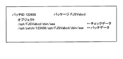
- FIG. 10 is a diagram illustrating a specific example of the contents of patch data.
- FIG. 11 is a diagram for explaining the state of the counter DB. It is assumed that the object in operation is arranged in “/ opt / FJSVabcd / sbin / aaa”.
- the patch data 123 describes “123456” as the patch ID value and “FJSVabcd” as the package name.
- the arrangement destination of the object the arrangement destination of the check data 122 and the patch data 123 is described.
- “/ Opt / FJSVabcd / sbin / aaa” is described in the arrangement location of the check data 122, and “aaa” is the object name of the check data 123.
- “/ Opt / patch / 123456 / opt / FJSVabcd / sbin / aaa” is described in the arrangement location of the patch data 123, and “aaa” is the object name of the patch data 122. That is, the arrangement destination of the patch data 123 is an arrangement destination in which an arrangement destination of an object to be originally executed is added under “/ opt / 123456 / opt”.
- the check data application unit 111 creates the counter DB 121 related to the patch ID “123456” described in the patch data 123.
- the state of the counter DB 121 immediately after creation is that the patch ID value is “123456”, and “/ opt / FJSVabcd / sbin / aaa” is stored as the object placement destination of the check data 122.
- “/ Opt / patch / 123456 / opt / FJSVabcd / sbin / aaa” is stored as the object placement destination of the patch data 123, and the initial value 0 is stored as the value of the counter 121d.
- the check data application unit 111 executes the object “aaa”, which is the check data 122, and when the correction data in the object “aaa” is passed, the counter value of the counter DB 121 is incremented by 1 by the counter process. Let Thereafter, the patch data application unit 113 checks the value of the counter corresponding to the patch ID “123456” stored in the counter DB 121 at the power-off or power-on timing.
- the patch data application unit 113 passes the correction portion even if the patch ID “123456” is corrected. Therefore, the patch data 123 is not applied. However, if the value of the counter corresponding to the patch ID “123456” is a number other than 0, the patch data application unit 113 passes the correction portion when the patch ID “123456” is corrected. 123 is applied. That is, the patch data application unit 113 replaces the object “aaa” of the check data 122 with the object “aaa” of the patch data 123.
- FIG. 12 is a diagram for explaining the state of the counter DB when there are two objects that are corrected for one patch ID.
- the state of the counter DB 121 immediately after the creation is that the patch ID value is “123456”, and there are two objects with modifications, “aaa” and “bbb”. Even if there are two objects with corrections to the patch ID “123456”, only one counter is used. Therefore, when either one of “aaa” and “bbb” passes the correction part, the check data application unit 111 adds 1 to one counter value.
- the patch data application unit 113 since the patch data application unit 113 does not pass the correction portion even if the patch ID “123456” is corrected, the objects “aaa” and “bbb” of the patch data 123 are not applied. However, when the counter value is a number other than 0, the patch data application unit 113 replaces the object “aaa” of the check data 122 with the object “aaa” of the patch data 123. Further, the patch data application unit 113 replaces the object “bbb” of the check data 122 with the object “bbb” of the patch data 123.
- the check data application unit 111 of the information processing apparatus 10 operates the check data 122 that incorporates the process of increasing the count when passing through the corrected portion when the program being operated is modified. Incorporate into. Then, the count-up determination unit 112 determines whether or not the check data 122 has been executed by executing a program on the information processing apparatus 10 based on whether or not the counter DB has been counted up at a predetermined timing. Further, when the count-up determination unit 112 determines that there is a patch (check data) application part whose count is up, the patch data application unit 113 displays the check data 122 that has been counted up as a correction part.
- the information processing apparatus 10 executes the check data 122 that incorporates the process of increasing the count when the correction location is passed, so whether or not the correction location has been passed by using the count is determined. Can be judged. For this reason, since the information processing apparatus 10 can apply the patch data 123 when passing through the correction portion, it can appropriately determine whether or not to apply the patch data 123.
- the patch data application unit 113 does not replace the check data 122 with the patch data 123 when the count-up determination unit 112 determines that the count is not up. According to such a configuration, the patch data application unit 113 does not replace the check data 122 with the patch data 123 when the count is not incremented, that is, when the correction point is not passed. For this reason, the patch data application unit 113 can prevent the occurrence of a level down due to the application even when the patch data 123 does not need to be applied.
- the count-up determination unit 112 determines whether or not the count is increased at the timing when the information processing apparatus 10 is stopped or the own apparatus is activated. According to such a configuration, the count-up determination unit 112 determines whether or not the count is up at a timing that does not hinder the operation of the program. Therefore, if the count is up, it is efficient.
- the patch data 123 can be replaced.
- the check data application unit 111 operates the check data 122 that incorporates a counting process that counts the number of times the correction part is executed when the correction part is executed when the program being operated is corrected. It explained that it applies to the program inside. Then, when the counter process in the check data 122 runs, the counter process increases the count corresponding to the patch ID of the patch data 123 delivered as a parameter.
- the counter process is not limited to this, and the count corresponding to the patch ID of the patch data 123 delivered as a parameter may be decreased.
- the patch data application unit 113 may replace the check data 122 with the patch data 123 when the count determination unit 112 determines that the count is down.
- the information processing apparatus 10 can be realized by mounting each function such as the control unit 11 and the storage unit 12 in an information processing apparatus such as a known personal computer or workstation.
- each component of each illustrated apparatus does not necessarily need to be physically configured as illustrated. That is, the specific mode of distribution / integration of each device is not limited to that shown in the figure, and all or a part thereof may be functionally or physically distributed or arbitrarily distributed in arbitrary units according to various loads or usage conditions. Can be integrated and configured.
- the count-up determination unit 112 and the patch data application unit 113 may be integrated as one unit.
- the check data application unit 111 may be distributed to a download unit that downloads the check data 321 and the patch data 322 and a check data application unit 111 that executes the downloaded check data 321.
- the storage unit 12 such as the counter DB 121 may be connected as an external device of the information processing apparatus 10 via a network.
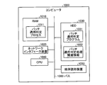
- FIG. 13 is a diagram illustrating a computer that executes a patch application determination program.
- the computer 1000 is the same as the information processing apparatus 10 illustrated in FIG. 1, and includes a RAM 1010, a network interface device 1020, an HDD 1030, a CPU 1040, a medium reading device 1050, and a bus 1060.
- the RAM 1010, the network interface device 1020, the HDD 1030, the CPU 1040, and the medium reading device 1050 are connected by a bus 1060.
- the patch creation server 40 and the patch release server 30 in FIG. 1 can also be realized by an information processing apparatus having the same configuration as that in FIG.
- the HDD 1030 stores a patch application determination program 1031 having the same function as that of the control unit 11 shown in FIG.
- the HDD 1030 stores patch application determination processing related information 1032 corresponding to the counter DB 121, the check data 122, and the patch data 123 illustrated in FIG.
- the patch application determination program 1031 functions as the patch application determination process 1011. Then, the patch application determination process 1011 expands the information read from the patch application determination processing related information 1032 to the area allocated to itself on the RAM 1010 as appropriate, and executes various data processing based on the expanded data and the like. .
- the medium reader 1050 reads the patch application determination program 1031 from a medium or the like that stores the patch application determination program 1031 even when the patch application determination program 1031 is not stored in the HDD 1030.
- Examples of the medium reading device 1050 include a CD-ROM and an optical disk device.
- the network interface device 1020 is a device connected to an external device via a network, and may be wired or wireless.
- the patch application determination program 1031 may be stored in another computer (or server) connected to the computer 1000 via a public line, the Internet, a LAN, a WAN (Wide Area Network), or the like. good.
- the computer 1000 reads and executes the patch application determination program 1031 from another computer or the like via the network interface device 1020.
Landscapes
- Engineering & Computer Science (AREA)
- Software Systems (AREA)
- General Engineering & Computer Science (AREA)
- Theoretical Computer Science (AREA)
- Computer Security & Cryptography (AREA)
- Physics & Mathematics (AREA)
- General Physics & Mathematics (AREA)
- Stored Programmes (AREA)
Abstract
La présente invention porte sur un appareil de traitement d'informations (10) comprenant : une unité d'application de vérification de données (111) qui applique, au programme en cours d'exécution, lorsqu'une révision doit être mise en œuvre pour un programme en cours d'exécution, des données de vérification, et dans laquelle est installée une procédure de traitement destinée à décompter le nombre de fois que le point à réviser est exécuté; une unité d'évaluation de décompte (112) qui évalue, à un instant prescrit, si le compteur indiquant le nombre de fois que le point à réviser est exécuté, a effectué un décompte du fait de l'application des données de vérification; et une unité d'application de données correctives (113) qui, lorsque le compteur est déterminé comme ayant effectué un décompte, remplace les données de vérification qui contiennent le point à réviser qui a été évalué comme ayant fait l'objet d'un décompte, par un programme révisé qui contient le point à réviser révisé. Ainsi, une évaluation visant à savoir s'il convient ou non d'appliquer un programme révisé peut être effectuée de façon appropriée.
Priority Applications (3)
| Application Number | Priority Date | Filing Date | Title |
|---|---|---|---|
| PCT/JP2011/056853 WO2012127635A1 (fr) | 2011-03-22 | 2011-03-22 | Appareil de traitement d'informations, programme d'évaluation d'application de révision et procédé d'évaluation d'application de révision |
| JP2013505705A JP5621914B2 (ja) | 2011-03-22 | 2011-03-22 | 情報処理装置、修正適用判定プログラムおよび修正適用判定方法 |
| US14/032,573 US20140019950A1 (en) | 2011-03-22 | 2013-09-20 | Information processing apparatus and method for determining whether a modified program is to be applied |
Applications Claiming Priority (1)
| Application Number | Priority Date | Filing Date | Title |
|---|---|---|---|
| PCT/JP2011/056853 WO2012127635A1 (fr) | 2011-03-22 | 2011-03-22 | Appareil de traitement d'informations, programme d'évaluation d'application de révision et procédé d'évaluation d'application de révision |
Related Child Applications (1)
| Application Number | Title | Priority Date | Filing Date |
|---|---|---|---|
| US14/032,573 Continuation US20140019950A1 (en) | 2011-03-22 | 2013-09-20 | Information processing apparatus and method for determining whether a modified program is to be applied |
Publications (1)
| Publication Number | Publication Date |
|---|---|
| WO2012127635A1 true WO2012127635A1 (fr) | 2012-09-27 |
Family
ID=46878828
Family Applications (1)
| Application Number | Title | Priority Date | Filing Date |
|---|---|---|---|
| PCT/JP2011/056853 Ceased WO2012127635A1 (fr) | 2011-03-22 | 2011-03-22 | Appareil de traitement d'informations, programme d'évaluation d'application de révision et procédé d'évaluation d'application de révision |
Country Status (3)
| Country | Link |
|---|---|
| US (1) | US20140019950A1 (fr) |
| JP (1) | JP5621914B2 (fr) |
| WO (1) | WO2012127635A1 (fr) |
Families Citing this family (2)
| Publication number | Priority date | Publication date | Assignee | Title |
|---|---|---|---|---|
| WO2015111067A1 (fr) * | 2014-01-24 | 2015-07-30 | Hewlett-Packard Development Company, L.P. | Intégration dynamique de correctifs sur des noyaux à l'aide de structures de données de stockage |
| GB2527060B (en) * | 2014-06-10 | 2021-09-01 | Arm Ip Ltd | Method and device for updating software executed from non-volatile memory |
Citations (3)
| Publication number | Priority date | Publication date | Assignee | Title |
|---|---|---|---|---|
| JP2000010766A (ja) * | 1998-06-18 | 2000-01-14 | Fujitsu Ltd | プログラム修正抽出適用システムおよび修正抽出適用プログラムを格納した記憶媒体 |
| JP2008198001A (ja) * | 2007-02-14 | 2008-08-28 | Hitachi Ltd | 修正パッチ選択支援システム及び支援方法 |
| JP2008269394A (ja) * | 2007-04-23 | 2008-11-06 | Konica Minolta Business Technologies Inc | 画像形成装置、プログラム更新システム、プログラム更新方法およびプログラム更新プログラム |
Family Cites Families (4)
| Publication number | Priority date | Publication date | Assignee | Title |
|---|---|---|---|---|
| US5481713A (en) * | 1993-05-06 | 1996-01-02 | Apple Computer, Inc. | Method and apparatus for patching code residing on a read only memory device |
| US7114150B2 (en) * | 2003-02-13 | 2006-09-26 | International Business Machines Corporation | Apparatus and method for dynamic instrumenting of code to minimize system perturbation |
| US7134121B2 (en) * | 2003-06-12 | 2006-11-07 | International Business Machines Corporation | Installing fixes based on usage |
| KR100983572B1 (ko) * | 2006-02-14 | 2010-09-24 | 후지쯔 가부시끼가이샤 | 패치 적용 방법 및 패치 적용 프로그램을 기록한 기록 매체 |
-
2011
- 2011-03-22 WO PCT/JP2011/056853 patent/WO2012127635A1/fr not_active Ceased
- 2011-03-22 JP JP2013505705A patent/JP5621914B2/ja not_active Expired - Fee Related
-
2013
- 2013-09-20 US US14/032,573 patent/US20140019950A1/en not_active Abandoned
Patent Citations (3)
| Publication number | Priority date | Publication date | Assignee | Title |
|---|---|---|---|---|
| JP2000010766A (ja) * | 1998-06-18 | 2000-01-14 | Fujitsu Ltd | プログラム修正抽出適用システムおよび修正抽出適用プログラムを格納した記憶媒体 |
| JP2008198001A (ja) * | 2007-02-14 | 2008-08-28 | Hitachi Ltd | 修正パッチ選択支援システム及び支援方法 |
| JP2008269394A (ja) * | 2007-04-23 | 2008-11-06 | Konica Minolta Business Technologies Inc | 画像形成装置、プログラム更新システム、プログラム更新方法およびプログラム更新プログラム |
Also Published As
| Publication number | Publication date |
|---|---|
| JPWO2012127635A1 (ja) | 2014-07-24 |
| JP5621914B2 (ja) | 2014-11-12 |
| US20140019950A1 (en) | 2014-01-16 |
Similar Documents
| Publication | Publication Date | Title |
|---|---|---|
| CN103455354B (zh) | 一种防止固件升级失败的方法和设备 | |
| CN102750191B (zh) | 用于启动固态非易失性存储设备内的刷新操作的方法 | |
| KR102192880B1 (ko) | 소프트웨어 재패키징 방지 방법 및 장치 | |
| CN103745158A (zh) | 修复系统漏洞的方法和装置 | |
| US20120296878A1 (en) | File set consistency verification system, file set consistency verification method, and file set consistency verification program | |
| CN106776122A (zh) | 一种基于Flash启动过程中主备保护的方法 | |
| CN109800005B (zh) | 一种客户端热更新方法及装置 | |
| CN104636171A (zh) | 升级的方法、装置及移动终端 | |
| JP6601491B2 (ja) | プログラム検証方法、検証プログラム、及び情報処理装置 | |
| AU2013380500B2 (en) | Database device, program, and data processing method | |
| WO2018024198A1 (fr) | Procédé de mise à niveau d'application utilisé dans un boîtier décodeur, système et boîtier décodeur | |
| CN113806139A (zh) | 操作系统恢复方法、设备、存储介质及计算机程序产品 | |
| JP5621914B2 (ja) | 情報処理装置、修正適用判定プログラムおよび修正適用判定方法 | |
| US8924951B2 (en) | Embedding patch lists within compiled program code | |
| JP6541912B2 (ja) | 情報処理装置およびアクセス管理プログラム | |
| CN103685471B (zh) | 一种以独占方式对软件客户端进行更新的方法及系统 | |
| CN109375953B (zh) | 一种操作系统启动方法及装置 | |
| KR20080087895A (ko) | 패치 적용 방법 및 패치 적용 프로그램을 기록한 기록 매체 | |
| CN104156281B (zh) | 一种嵌入式系统中启动磁盘备份的方法及其系统 | |
| JP7411902B1 (ja) | 情報処理装置、情報処理装置の制御方法及びプログラム | |
| CN105335095B (zh) | 闪存文件系统的处理方法及装置 | |
| JP5744078B2 (ja) | 組み込み機器制御システム、組み込み機器制御装置、及び組み込み機器制御装置の制御方法 | |
| US20110185353A1 (en) | Mitigating Problems Arising From Incompatible Software | |
| CN112905218B (zh) | 一种固件升级方法、装置及设备 | |
| CN110928570A (zh) | 一种固件升级的方法及装置、可读存储介质 |
Legal Events
| Date | Code | Title | Description |
|---|---|---|---|
| 121 | Ep: the epo has been informed by wipo that ep was designated in this application |
Ref document number: 11861577 Country of ref document: EP Kind code of ref document: A1 |
|
| ENP | Entry into the national phase |
Ref document number: 2013505705 Country of ref document: JP Kind code of ref document: A |
|
| NENP | Non-entry into the national phase |
Ref country code: DE |
|
| 122 | Ep: pct application non-entry in european phase |
Ref document number: 11861577 Country of ref document: EP Kind code of ref document: A1 |