WO2012127644A1 - Système d'appareils de nœud de communication, appareil, et procédé - Google Patents
Système d'appareils de nœud de communication, appareil, et procédé Download PDFInfo
- Publication number
- WO2012127644A1 WO2012127644A1 PCT/JP2011/056928 JP2011056928W WO2012127644A1 WO 2012127644 A1 WO2012127644 A1 WO 2012127644A1 JP 2011056928 W JP2011056928 W JP 2011056928W WO 2012127644 A1 WO2012127644 A1 WO 2012127644A1
- Authority
- WO
- WIPO (PCT)
- Prior art keywords
- processing unit
- information processing
- packet
- communication node
- standby
- Prior art date
- Legal status (The legal status is an assumption and is not a legal conclusion. Google has not performed a legal analysis and makes no representation as to the accuracy of the status listed.)
- Ceased
Links
Images






Classifications
-
- H—ELECTRICITY
- H04—ELECTRIC COMMUNICATION TECHNIQUE
- H04L—TRANSMISSION OF DIGITAL INFORMATION, e.g. TELEGRAPHIC COMMUNICATION
- H04L41/00—Arrangements for maintenance, administration or management of data switching networks, e.g. of packet switching networks
- H04L41/06—Management of faults, events, alarms or notifications
- H04L41/0654—Management of faults, events, alarms or notifications using network fault recovery
- H04L41/0668—Management of faults, events, alarms or notifications using network fault recovery by dynamic selection of recovery network elements, e.g. replacement by the most appropriate element after failure
-
- H—ELECTRICITY
- H04—ELECTRIC COMMUNICATION TECHNIQUE
- H04L—TRANSMISSION OF DIGITAL INFORMATION, e.g. TELEGRAPHIC COMMUNICATION
- H04L49/00—Packet switching elements
- H04L49/55—Prevention, detection or correction of errors
- H04L49/557—Error correction, e.g. fault recovery or fault tolerance
Definitions
- the present invention relates to a communication device and a communication system, and more particularly, to a technology for continuing information processing and communication processing by making the device redundant.
- Patent Document 1 discloses a problem that a non-redundant section of a layer 2 network is shortened and a route is generated when a network failure occurs. Is provided as a layer 2 network redundancy system that can be switched from an active system to a standby system in a short time.
- the subscriber's home bases A and B are connected to each other via a layer 2 network made redundant by multiplexing each switch.
- the layer 2 network is connected to the active system (m).
- Each of the in-home bases A and B includes the subscriber M / Cs 10 and 20 that are duplicated, and either the active or standby system of each subscriber M / C is a subscriber terminal.
- Port selectors 11 and 21 to be selectively connected are arranged.
- Patent Document 2 makes it possible to perform data synchronization for maintaining a communication service between duplexed configurations while ensuring compatibility with function expansion and independence of each function module as a problem. It is described.
- the functional modules 502-1 and 502-2 installed in the communication control device 600 are installed as independent modules and are synchronized between the active system and the standby system.
- the duplex synchronization control unit 500 (500-1, 500-2) that performs data notification processing includes the synchronization target data from the functional module 502-1 operating as the active system, and the data At least a notification destination module identifier for identifying a module that is a notification destination is received as data accompanying the data, and the received data is received by the functional module 502-2 operating as a standby system based on the received notification destination module identifier. Hand over.
- Patent Document 2 it is necessary to transfer data necessary for the standby system from the active system at the time of dual system switching, and therefore a predetermined time is required. Become.
- a communication node device system is a working and standby communication node device including a switch processing unit that performs packet transfer processing and an information processing unit that executes an application.
- the switch processing unit provides a communication node device system configured to copy and transfer packets to the active information processing unit and the standby information processing unit.
- the present invention is a communication node device that is used with both the active system and the standby system operating, and executes a switch processing unit that performs packet transfer processing and an application.
- a transfer processing unit that, when operating as an active switch processing unit, copies a packet to be processed by the information processing unit and forwards the packet to two output destinations.
- the information processing unit confirms the mutual operation state between the active system and the standby system, and assumes that a failure has occurred if the active information processing unit does not return a response.
- a mutual monitoring processing unit for operating the processing unit as an active system, and a stop processing unit for stopping packet output from the information processing unit by an application when operating as a standby information processing unit It provides a communication node device configuration with.
- both the active and standby communication node devices including a switch processing unit that performs packet transfer processing and an information processing unit that executes an application are put into operation.
- the switch processing unit operates as an active switch processing unit, it copies the packet that is the information processing target in the information processing unit and forwards it to two output destinations.
- the processing unit confirms the operation state between the active information processing unit and the standby information processing unit, and assumes that a failure has occurred when the active information processing unit does not return a response
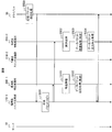
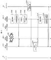
- FIG. 8 is a diagram illustrating an example of a flowchart according to the first embodiment when a failure occurs in the active system in FIG. 7.
- FIG. 8 is a diagram illustrating an example of a flowchart according to the first embodiment when a failure occurs in the active system in FIG. 7.
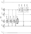
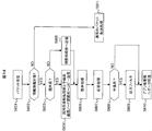
- FIG. 9 is a diagram illustrating an example of a flowchart when a failure occurs in the active system in FIG. 8 according to the first embodiment.
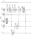
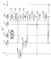
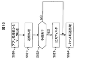
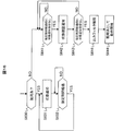
- FIG. 10 is a diagram illustrating an example of a flowchart when a failure occurs in the active system in FIG. 9 according to the first embodiment. It is a figure which shows the example of the flowchart of the packet reception process of the communication node based on 1st Example. It is a figure which shows the example of the flowchart of the packet transmission process of the communication node based on 1st Example. It is a figure which shows the example of the flowchart of the failure detection of a communication node, and system switching based on 1st Example. It is a figure which shows the example of an input filter table based on 2nd Example.
- each functional block in the communication node device may be referred to as “function”, “means”, “processing unit”, or the like.
- functions functions
- processing unit or the like.
- mutual monitoring function means
- mutual monitoring processing unit and the like.
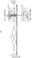
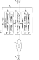
- FIG. 1 is a system configuration diagram illustrating the first embodiment.
- WAN wide area network
- the communication node device 100 includes a switch processing unit 110 for performing packet transfer and an information processing unit 200 for performing information processing of layer 4 or higher.
- the switch processing unit 110 includes a conditional destination copy table 111 described later, which is a characteristic function of the present embodiment.
- the information processing unit 200 is also characterized by a mutual monitoring processing unit 201, a selective input stop processing unit 202, and a selective output stop processing unit 203, which will be described later. Is provided.
- FIG. 2 shows an example of information processing in the information processing unit 200 of the active communication node 100-1 in this embodiment.
- the client 30 at the base accesses the server 10 of the data center via the WAN 20 and receives an information processing service provision using the database 420 on the server 10.
- the communication delay is as large as 200 ms, and the communication performance of the corresponding information processing deteriorates.
- the information processing service itself A problem occurs that the response speed decreases.
- a mode in which the processing 410 is performed by the communication node device 100 having an information processing function capable of information processing in the vicinity of the client 30 can be considered.
- the database 420 itself is huge, and it is generally difficult and inefficient to arrange everything in the communication node device 100.
- the system of this embodiment assumes a mode in which information processing is performed while only data used in the corresponding processing 410 is transferred to the information processing unit 200 of the communication node device 100.
- the information processing time viewed from the client 30 can be shortened by the above processing, when the information processing unit 200 performing information processing in the communication node device 100 fails, the information processing service Communication processing and information processing are stopped. Therefore, in the system of the present embodiment, the active communication node device 100-1 and the standby communication node device 100-2 adjacent thereto are used, and the information processing unit 200-1 of the active communication node device 100-1 uses the failure. Even if the error occurs, the information processing unit 200-2 of the standby communication node apparatus 100-2 provides means for continuing the corresponding information processing service. The details will be described below.
- the switch processing unit 110 of the communication node device 100 includes a packet transfer processing unit 112 included in a normal packet transfer device, a network interface (not shown), and various transfer tables such as a routing table. With reference to the transfer table, packet transfer is performed based on packet header information such as a destination IP (Internet Protocol) address and a destination MAC (Media Access Control) address. Further, a conditional destination copy table 111 shown in FIG. 1 is provided as a transfer table characteristic of the system of this embodiment. In this specification, the conditional destination copy table 111 and the packet transfer processing unit 112 may be referred to as a transfer processing unit.
- the conditional destination copy table 111 includes at least a search key 300 field, an output port 1 320, and an output port 2 321 field.
- the search key 300 includes information such as a 5-tuple indicated by a source IP address 301, a destination IP address 302, a protocol 303, a source port 304, and a destination port 305.
- a VLAN ID Virtual Local Area Network Identifier
- arbitrary header information may be used as a search key.
- the flow of a packet that matches the search key is forcibly sent to the output destination of the communication node device indicated by the output port 1 to 320 and the output port 2 to 321 regardless of the original destination IP address or destination MAC address. Copy and transfer.
- the packet copy by the conditional destination copy table 111 is similar to the port mirroring function provided in a normal switch device in that the packet contents are copied to a certain output port. Packet copy differs in that it also allows packet input from the opposite direction. This is because port mirroring is generally intended to measure traffic by connecting a measuring device such as a network analyzer to the end of a port through which a copy packet flows.
- a measuring device such as a network analyzer
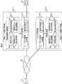
- a line 280 and a line 281 are provided as shown in FIG. Then, the active switch 110-1 uses the transfer to the information processing unit 200-1 as the original transfer, and transfers the copy packet to the standby switch 110-2 via the line 280 using the port mirroring function. .
- the line 281 may be used for transfer from the standby switch 110-2 to the active switch 110-1.
- two lines 280 and 281 are provided, but the number of lines may be further increased.
- a line for passing a packet to be transmitted / received to / from the client-side network to the standby switch 110-2, a line to return from the switch 110-2 to the switch 110-1, and a packet to be transmitted / received to / from the server-side network are reserved. It is also possible to provide four lines, a line passing to the system switch 110-2, and a line returning from the switch 110-2 to the switch 110-1.
- a general data line for exchanging packets with the server and the client may be divided from a control line for exchanging a packet dedicated to a status notification packet (heartbeat) described later.
- the corresponding packet flow is used. It is possible to transfer to both the information processing unit 200-1 of the system and the communication node device 100-2 of the standby system.
- packet flow is transferred to information processing section 200-2 by packet transfer processing section 112 of switch processing section 110-2.
- the corresponding packet flow is received and processed by both the active information processing unit 200-1 and the standby information processing unit 200-2.
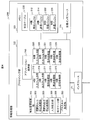
- the information processing unit 200 selects the input packet flow, the mutual monitoring processing unit 201 for performing status notification, failure detection, and system switching processing between the active system and the standby system.
- a selective input stop processing unit 202 that performs control for capturing automatically and a selective output stop processing unit 203 that performs control to selectively stop the output packet flow.
- the selective input stop processing unit 202 and the selective output stop processing unit 203 may be referred to as a stop processing unit.
- the core process part 204 which processes information in FIG. 1 corresponds to parts other than the said three components in the various functional blocks of FIG.
- the input distribution unit 205 performs a process of distributing the input packet to any one of the A-side input filter unit 210, the B-side input filter unit 220, the pass-through processing unit 250, and the mutual monitoring processing unit 201.
- a packet that is processed by an application processing unit 240 is a packet that flows from the server 10 side toward the client 30 side.
- the packet from the mutual monitoring processing unit 201 outside the own system is distributed to the mutual monitoring processing unit 201 of the own system.
- Other packets are distributed to the pass-through processing unit 250.
- the output merge unit 206 performs a process of transmitting packets from the A side output filter unit 216, the B side output filter unit 226, the mutual monitoring processing unit 201, and the pass-through processing unit 250 to the outside of the information processing unit.
- the selective input stop processing unit 202 uses the A-side input filter unit 210 and the B-side input filter unit 220 to filter, that is, stop (exclude) a specific packet flow.
- both the active information processing unit 200-1 and the standby information processing unit 200-2 process all packet flows input to the A side input filter unit 210 and the B side input filter unit 220. Import without filtering. An example of filtering a part will be described in the second embodiment.
- the selective output stop processing unit 203 When the selective output stop processing unit 203 operates as the standby information processing unit 200-2, it outputs the packet output to the server 10 and the client 30 through the A side output filter unit 216 and the B side output filter unit 226. Filter using, that is, stop processing. Similarly, the pass-through processing unit 250 performs a process of stopping the packet output.
- the filter is released. That is, the output of the packet that was supposed to be stopped is permitted.
- the pass-through processing unit 250 transfers the packet input from the input distribution unit 205 to the output merge unit 206 as it is without performing any processing. If the switch processing unit 110 is set not to transfer a packet flow that does not require processing by the application processing unit 240 of the information processing unit 200 to the information processing unit 200, basically, the switch processing unit 110 does not pass to the pass-through processing unit 250. Packets are not forwarded.
- the A side alignment processing unit 211, the A side retransmission processing unit 213, and the A side transmission processing unit 215 are constituent elements of the response confirmation type communication protocol processing unit on the A side.
- the response confirmation type communication protocol means a communication protocol for performing data delivery confirmation such as TCP (Transmission Control Protocol), and the response confirmation type communication protocol processing unit is a functional unit that executes the protocol. Means.
- the A-side alignment processing unit 211 receives the packet and writes the data packet to the A-side reception buffer 212.
- the A-side alignment processing unit 211 checks whether the data packets have arrived in order based on a sequence number or the like, and if there is an out-of-order, sends a response packet for requesting retransmission of the corresponding packet to A It transmits from the side transmission process part 215. If the order is correct, a response packet notifying normal arrival is transmitted from the A-side transmission processing unit 215.
- the A-side transmission processing unit 215 performs processing for transmitting the data written by the application processing unit 240 to the A-side transmission buffer 214 as a data packet. .
- the A-side retransmission processing unit 213 deletes the corresponding data from the A-side transmission buffer 214.
- the corresponding data is retransmitted from the A-side transmission buffer 214.
- Packets also apply to the B-side input filter unit 220, the B-side output filter unit 226, the B-side alignment processing unit 221, the B-side retransmission processing unit 223, the B-side transmission processing unit 225, the B-side reception buffer 222, and the B-side transmission buffer 224.
- the same process as that on the A side is performed only in the direction in which the air flows.
- the B-side alignment processing unit 221, the B-side retransmission processing unit 223, and the B-side transmission processing unit 225 are collectively referred to as a response confirmation type communication protocol processing unit, and are used as function units for executing the response confirmation type communication protocol.
- the application processing unit 240 receives data used by the application via the A side reception buffer 212 and the B side reception buffer 222, performs programmed communication processing and information processing, and outputs the result on the opposite side to the input. Write to the A side transmission buffer 214 and the B side transmission buffer 224.
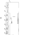
- the state table 230 includes a search key 231, an A-side response confirmation type protocol state 250, a B-side response confirmation type protocol state 260, an application data usage state 270, and the like as shown in FIG. 6 as an example.
- the A-side response confirmation type protocol state 250 includes, for example, a protocol state 251 indicating a connection state (established, connected, terminated), a reception buffer aligned pointer 252, a reception buffer unaligned pointer 253, a reception buffer The transmission pointer 254 (to the application processing unit side), the transmission pointer (outside) 255 of the transmission buffer, the response (ACK) waiting pointer 256 of the transmission buffer, the sequence number 257, and the like.
- the sequence number 257 is not only for the purpose of confirming the sequence number of the current packet flow, but also from the transmission processing unit on the transmission side and the standby system in the communication processing from the A side to the B side or vice versa. It can also be used for the purpose of aligning the sequence numbers of packets to the same value. This is because when the failure occurs in the active information processing unit 200-1 and the output from the standby information processing unit 200-2 is validated, the active information processing unit 200-1 serves as a reference. This is a process necessary for the standby information processing unit 200-2 to use the same sequence number as the sequence number of the used packet flow.
- the response confirmation type protocol on the opposite side may use the delivered sequence number itself, or may use a new sequence number obtained by adding or subtracting a certain value to the sequence number. .
- the active information processing unit 200-1 and the standby information processing unit 200-2 use the same constant value.
- the B side response confirmation type protocol state 260 is the same as the A side response confirmation type protocol state 250.
- the application data usage state 270 depends on the application. For example, the application state 271 (operating, suspended, data waiting state, etc.), the input data direction 272 from the response confirmation type protocol, the head pointer of the input data 273, a pointer 274 for acquiring the size information of the input data, an output data direction 275 to the response confirmation type protocol, a head pointer 276 of the output data, a pointer 277 for acquiring the size information of the output data, and the like.
- the information processing unit 200 in this embodiment may be configured with dedicated hardware, but as shown in FIG. 4, a processing unit 122 using a general-purpose processor, a network processor, or the like that functions as a processing unit.
- the memory 123 as a storage unit, the expansion interface 124 for connecting other devices, and the interface 121 for connecting to the main body of the switch processing unit 110 may be used.
- the processing unit 122 the mutual monitoring processing unit 201, the selective input stop processing unit 202, the selective output stop unit 203, the input distribution unit 205, the output merge unit 206, the A side input filter unit 210, and the A side output Filter unit 216, A side alignment processing unit 211, A side retransmission processing unit 213, A side transmission processing unit 215, B side input filter unit 220, B side output filter unit 226, B side alignment processing unit 221 and B side retransmission processing
- a program that simulates the unit 223, the B-side transmission processing unit 225, the pass-through processing unit 250, and the application processing unit 240 is executed.
- the state table 230, the A-side reception buffer 212, the A-side transmission buffer 214, the B-side reception buffer 222, and the B-side transmission buffer 224 are stored on the memory 123 and used from the processing unit 122.
- the configuration of the information processing unit 200 of the communication node device 100 has been described above.
- both the active information processing unit 200-1 and the standby information processing unit 200-2 are in an operating state. That is, the standby system is not in cold standby but in a hot standby state, and the active information processing unit 200-1 can immediately continue processing when a failure occurs.
- the communication node device 100 that has received the packet uses the switch processing unit 110 to check whether or not the packet is an information processing target (S601 ⁇ S602). If the packet is not an information processing target, normal packet transfer processing is performed (S611).
- the packet When the packet is an information processing target, if it is the active communication node device 100-1, the packet is transmitted to the active information processing unit 200-1 regardless of the destination IP address or the destination MAC address of the packet. Copy transmission is performed toward the standby communication node apparatus 100-2 (S603 ⁇ S604). On the other hand, in the case of the standby communication node apparatus 100-2, the packet is transmitted to the information processing unit 200-2 (S603 ⁇ S605). When the information processing unit 200 receives a packet to be processed, the information processing unit 200 takes the packet into the response confirmation communication protocol via the input distribution unit 205 and the output filter unit 210 (220).
- the same packet is written to the reception buffer 212 (222), and if the packet is a data packet, the alignment processing unit 211 (221) performs alignment processing (S606), and the sequence included in the header of the data packet as response processing If the data packet arrives in order based on the number or the like, a response packet indicating normal arrival is returned. If not in order, a response packet notifying the retransmission request is returned (S607). If the packet is a response packet indicating a retransmission request, the packet of the corresponding data is retransmitted from the transmission buffer 214 (224). Otherwise, the corresponding data is deleted from the transmission buffer 214 (224) as a response process (S606).
- the response packet or data packet is transmitted by the response process S607.
- the output of the response packet or data packet is filtered by the output filter unit 216 (226). However, it is not output to the outside (S608 ⁇ S609). Output to the outside as usual only when the system is active.
- the transmission processing unit 215 (225) of the response confirmation communication protocol that has received the data from the application processing unit 240 via the transmission buffer 214 (224) performs transmission processing with the data as a data packet (S620 ⁇ S621).
- the switch processing unit 110 transfers the packet according to the destination described in the routing table or the like by the packet transfer processing unit 112 (S624).
- the information processing unit 200-1 of the active communication node device 100-1 uses the mutual monitoring processing unit 201 to provide information on the standby communication node device 100-2.
- a status notification packet is transmitted to the processing unit 200-2 (heartbeat) (S630 ⁇ S631).
- a status notification packet (heartbeat) is transmitted to the information processing unit 200-2 of the standby communication node apparatus 100-2.
- the information processing unit 200-2 of the standby communication node apparatus 100-2 uses the mutual monitoring processing unit 201 to receive information from the active communication node apparatus 100-1. Observe presence / absence of status notification packet (heartbeat). If the status notification packet is received within the specified period set for the mutual monitoring processing unit 201, the presence / absence of the status notification packet is continuously observed (S641).
- a status confirmation notification is transmitted to the mutual monitoring processing unit 201 of the active communication node device 100-1 (S641 ⁇ S642). If there is a corresponding reply from the mutual monitoring processing unit 201 of the active communication node device 100-1, the information processing unit 200-1 of the active communication node device 100-1 is operating, so that the state of S641 again Then, the operation as a standby system is continued (S643 ⁇ S641).
- the selective output stop processing unit 201 of the information processing unit 200-2 cancels the packet output stop by the filter of the output filter unit 216 (226) (S643 ⁇ S644), and starts the operation as the active system (S645).
- both the active switch processing unit 110-1 and the standby switch processing unit 110-2 perform processing contents.
- the standby information processing unit 200-2 can continue the corresponding information processing and communication processing without any change. For example, processing such as rewriting of the IP address of the information processing unit 200 is not required at the time of takeover.
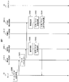
- the server 10 After establishing the connection with the client 30, the server 10 transmits a data packet to the client 30 (S500). If the active communication node device 100-1 on the route is a communication data packet to be processed, the switch processing unit 110-1 does not depend on the destination IP address or the destination MAC address described in the data packet. -1 is used to copy and transfer the data packet to the information processing unit 200-1 and the standby communication node apparatus 100-2 (S501).
- the active information processing unit 200-1 and the standby information processing unit 200-2 that have received the data packet perform the alignment process described above on the data packet (S502). If it is determined that the data packet has not arrived in order with reference to the sequence number or the like, a retransmission request response packet transmission process is performed (S503). At this time, the standby information processing unit 200-2 stops the output of the response packet by the processing provided by the selective output stop processing unit 203 and the output filter unit 216 (226), and does not output it to the outside ( Therefore, only the response packet from the active system is transmitted to the server 10.
- the active information processing unit 200-1 and the standby information processing unit 200-2 Performs transmission processing of a response packet indicating that the data packet has been correctly received (S503).
- the standby information processing unit 200-2 stops the output of the response packet by the processing provided by the selective output stop processing unit 203 and the output filter unit 216 (226), and does not output it to the outside ( S504).
- both the active information processing unit 200-1 and the standby information processing unit 200-2 pass the corresponding data to the application processing unit 240 via the reception buffer 212 (222), and perform application processing. Implement (S505).
- the data after application processing is transmitted as a data packet via the transmission buffer 224 (214) in the opposite direction to reception (S506).
- the standby information processing unit 200-2 stops the output of the data packet and does not output it to the outside by the processing provided by the selective output stop processing unit 203 and the output filter unit 226 (216) ( Therefore, only the data packet from the active system is transmitted to the client 30.
- the client 30 that has received the data packet transmits a response packet to the active communication node device 100-1 (S530).
- the active communication node device 100-1 that has received the response packet uses the switch processing unit 110-1 to transmit the response packet to its own information regardless of the destination IP address or the destination MAC address described in the response packet. Copy and transfer to the processing unit 200-1 and the standby communication node apparatus 100-2 (S531).
- both the active information processing unit 200-1 and the standby information processing unit 200-2 perform retransmission processing of the corresponding data packet, and the data packet is again transmitted. It tries to transmit toward the client 30 (S532 ⁇ S533).
- the standby information processing unit 200-2 stops the output of the data packet by the processing provided by the selective output stop processing unit 203 and the output filter unit 226 (216), and does not output it to the outside ( Therefore, only the data packet from the active system is transmitted to the client 30.
- the response packet is a response packet indicating that the data packet has been correctly received, neither the active information processing unit 200-1 nor the standby information processing unit 200-2 performs the retransmission process S532,
- the corresponding data packet is deleted from the transmission buffer 224 (214).
- the cooperative operation of the active communication node apparatus 100-1 and the standby communication node apparatus 100-2 when no failure has occurred has been described.
- the information processing unit 200-1 of the active communication node device 100-1 When the information processing unit 200-1 of the active communication node device 100-1 is in an operating state, the information processing unit 200-1 is in an operating state with respect to the information processing unit 200-2 of the standby communication node device 100-2.
- the operation of transmitting a status notification packet indicating this is continued (heartbeat) (S550 ⁇ S551 ⁇ S552).
- the information processing unit 200-2 of the standby communication node apparatus 100-2 sends a status confirmation notification packet to the active communication node apparatus 100-1.
- the information is transmitted to the information processing unit 200-1 (S561). If there is no response to the status confirmation notification packet within a predetermined period (S562), the information processing unit 200-2 of the standby communication node apparatus 100-2 performs the information processing of the active communication node apparatus 100-1.
- the selective output stop processing unit 201 of the standby information processing unit 200-2 releases the packet output stop by the filter of the output filter unit 216 (226) (S563). Then, the operation as an active system is started.
- the information processing unit 200-2 of the standby communication node device 100-2 detects the failure S560, the status confirmation notification S561, and no response. Confirmation S562 and output filter cancellation S563 are performed, and the operation as the active system is started.
- the data packet transmitted from the server 10 in S500 is copied by the switch processing unit 110-1 of the active communication node device 100-1 (S501), and then the active information processing unit 200- 1 and the backup information processing unit 200-2.
- the active information processing unit 200-1 is down due to a failure, only the standby information processing unit 200-2 performs an alignment process S502 and an output process S503 of a response packet including a retransmission request.
- the output filter of the standby information processing unit 200-2 is released, the response packet from here is transferred to the server 10.
- the same packet may be temporarily transmitted from the active information processing unit 200-1 and the standby information processing unit 200-2 at the time of system switching. There is no problem because the packet is discarded. In addition, it is possible that the communication from the standby information processing unit 200-2 that has started the operation as the active system may disappear without the output filter being released in time, but there is no response in the expected order. There is no problem because the processing of S500 and S501 is repeated again.
- the data packet transmitted from the server 10 in S500 is copied by the switch processing unit 110-1 of the active communication node device 100-1 (S501), and then the active system.
- Information processing unit 200-1 and the standby information processing unit 200-2 are down due to a failure, only the standby information processing unit 200-2 that has started the operation as the active system can correctly execute the alignment process S502 and the data.
- Response packet transmission processing to the effect that the packet has been received is performed (S503).
- the output filter of the standby information processing unit 200-2 is released, the response packet from the standby information processing unit 200-2 is transferred to the server 10.
- the standby information processing unit 200-2 that has started to operate as the active system passes the corresponding data to the application processing unit 240 via the reception buffer 212 (222), and performs application processing (S505).
- the data after application processing is transmitted as a data packet via the transmission buffer 224 (214) in the opposite direction to reception (S506).
- the client 30 replaces the previous information processing unit 200-1 with the previous system. Data packets can be transmitted to
- the packet transfer that is, the communication session is the same as the communication session performed in the server 10, the client 30, and the active information processing unit 200-1 before the failure occurs, and starts operating as the active system.
- the same communication session and information processing are continued even if the communication between the standby communication node apparatus 100-2, the server 10, and the client 30 is replaced.
- the client 30 that has received the data packet transmits a response packet to the active communication node device 100-1 (S530).
- the active communication node device 100-1 that has received the response packet uses the switch processing unit 110-1 to send the response packet to the active node regardless of the destination IP address or the destination MAC address described in the response packet.
- the information is copied and transferred to the information processing unit 200-1 and the standby communication node apparatus 100-2 (S531).
- the active information processing unit 200-1 is down due to a failure, only the standby information processing unit 200-2 that has started operation as the active system has been copied and transferred. Processing on the packet can be performed.
- the standby information processing unit 200-2 that has started to operate as the active system performs retransmission processing of the corresponding data packet, and sends the data packet to the client 30 again. (S532 ⁇ S533). At this time, since the output information filter of the standby information processing unit 200-2 that has started operating as the active system has been released, the client 30 replaces the previous information processing unit 200-1 with the previous system. Data packets can be transmitted to
- the standby information processing unit 200-2 that has started operating as the active system does not perform the retransmission process S532, and does not perform the retransmission process S532. From (214), the corresponding data packet is deleted.
- the same packet may be temporarily transmitted from the active information processing unit 200-1 and the standby information processing unit 200-2 at the time of system switching. There is no problem because only the packet is discarded.
- communication from the standby information processing unit 200-2 that has started the operation as the active system may disappear before the output filter is released in time, it is assumed that there was no expected data packet transmission. There is no problem because the processing after S530 is repeated again.
- the standby information processing unit 200-2 is operated in a non-redundant state (single system). It is desirable to replace the processing unit 200-1 with a normal one. Once this replacement is completed, the replaced information processing unit 200-1 may start operation as a standby system.
- Example 2 describes an example of a method for achieving both improvement in processing efficiency as a system and protection of important processing.
- the active information processing unit 200-1 and the standby information processing unit 200-2 perform the same information processing and communication processing.
- the utilization efficiency of the system is 50%.
- a concept of priority is set for communication processing / information processing to be handled, and important processing with high priority set is operated in both the active system and the standby system, and one of them causes a failure.
- the best effort processing with a low priority is performed only in one system while allowing the processing to continue.
- the operation of this embodiment makes it possible to achieve both protection of important processing and realization of processing efficiency exceeding 50% as a system.
- the input filter units 210 and 220 shown in FIG. 3 include the input filter table 400 shown in FIG.
- the input filter table 400 includes fields for a search key 401 and a priority 402.
- a search key 401 is set by a combination of 5-tuple information or the like, and a packet flow group of the corresponding process is classified into a high priority packet flow H and a low priority packet flow L. Further, for the packet flow defined as the low priority flow L, the packet flow handled only by the active information processing unit 200-1 is classified as the packet flow LA for convenience. Similarly, a packet flow handled only by the standby information processing unit 200-2 is classified as a packet flow LS for convenience. These classification results are set to priority 402.
- the input filter unit 210 (220) of the active information processing unit 200-1 is set to filter the packet flow LS, and the alignment processing unit 211 (221) ) And the retransmission of the packet flow LS to the retransmission processing unit 213 (223).
- the other high priority packet flows H and packet flows LA are captured.
- the input filter unit 210 (220) of the standby information processing unit 200-2 is set so as to filter the packet flow LA, and is sent to the alignment processing unit 211 (221) and the retransmission processing unit 213 (223). Ingestion of the packet flow LA. Other high priority packet flows H and packet flows LS are captured.
- the output filter unit 216 (226) of the standby information processing unit 200-2 will be described as processing for the output side of the information processing unit 200 according to the second embodiment with reference to FIG.
- the output filter unit 216 (226) includes an output filter table 410 shown in FIG. Similar to the input filter table 400, the output filter table 410 includes fields for a search key 411 and a priority 412. The values of the search key 411 and priority 412 set in the output filter table 410 are the same as the values of the search key 401 and priority 402 of the input filter table 400, respectively.
- the output filter unit 216 uses the output filter table 410 to filter and stop the output of the high priority packet flow H among the input high priority packet flow H and low priority packet flow LS. On the other hand, the output of the low priority packet flow LS is not filtered.
- the output filter unit 216 (226) outputs the output until then.
- the output filter for the stopped high priority packet flow H is canceled.
- both the high-priority packet flow H and the low-priority packet flow LS are output from the standby information processing unit 200-2 that has started to operate as the active system.
- Other operations and processes are the same as those in the first embodiment.
- the utilization efficiency will be described as the system of the information processing unit 200 in the present embodiment.
- the ratio of the packet flow LA and the packet flow LB is the same.
- the priority is set while operating in both the active system and the standby system so that processing can continue even if one of them fails.
- the best effort processing set to a low value the processing efficiency exceeding 50% and the protection of the important processing can be achieved at the same time by executing the processing with only one system.
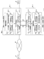
- the active information processing unit 200-1 As the output port 1 (320) of the conditional destination copy table 111 and the standby information processing unit 200-2 as the output port 2 (321), it is applicable.
- the packet flow can be copied and transferred to both the active information processing unit 200-1 and the standby information processing unit 200-2 for processing.
- the operations of the active information processing unit 200-1 and the standby information processing unit 200-2 are exactly the same as described in the first embodiment.
- This configuration is characterized in that information processing within a physically single communication node device 100 can be made redundant.
- the active communication node device 100-1 includes two information processing units 200, as in FIG. 17, and also includes the standby communication node device 100-2 including the information processing unit 200-2 as in FIG. It is a configuration.
- the active information processing unit 200-1 is designated as output port 1 (320) and the standby communication node apparatus 100-2 is designated as output port 2 (321).
- the active information processing unit 200-1 is designated as output port 1 (320)
- the standby information processing unit 200-2 is designated as output port 2 (321). .
- the corresponding packet flow group A is sent to both the active information processing unit 200-1 and the information processing unit 200-2 (corresponding to FIG. 1) of the standby communication node apparatus 100-2. Can be transferred and processed.
- the corresponding packet flow group B corresponds to both the active information processing unit 200-1 and the standby information processing unit 200-2 (corresponding to FIG. 19) in the active communication node device 100-1. The packet flow can be copied and processed.
- the information processing unit 200-2 (corresponding to FIG. 1) of the standby communication node device 100-2, the spare in the active communication node device 100-1
- Corresponding information processing and communication processing can be continuously executed by both of the information processing units 200-2 (corresponding to FIG. 19).
- the node apparatus 100 may be configured to include an information processing unit that includes the functions of the active information processing unit 200-1 and the standby information processing unit 200-2.
- the active switch processing unit 110-1 checks whether or not a packet received from a network outside the apparatus is an information processing target.
- the packet is copied using the conditional destination copy table 111, and one packet is transmitted to the active information processing unit 200-1 as in the first embodiment.
- the other packet is transmitted again to the packet transfer processing unit 112 of the active switch processing unit 110-1, where the source IP address of the corresponding packet is the active communication node device 100-1 and the destination IP address.
- the communication node apparatus 100-2 of the standby system has a protocol number indicating that it indicates communication between the two apparatuses, and is transmitted to the WAN 20.
- the packet transfer processing unit 112 of the switch processing unit 110-2 releases the encapsulation, and the standby information processing unit 200 To -2.
- the processes in the active information processing unit 200-1 and the standby information processing unit 200-2 are the same as those in the first embodiment.
- the packet output from the standby information processing unit 200-2 is validated as in the first embodiment.
- the source IP address is set to the standby system.
- the communication node device 100-2 is encapsulated so that the destination IP address is the active communication node device 100-1 and the protocol number is a number designating the communication between the two devices, and is transmitted to the WAN 20 .
- the packet transfer processing unit 112 of the switch processing unit 110-1 releases the encapsulation, and the original destination described in the packet Forward to.
- the standby information processing unit 200-2 can provide means for continuing the processing.
- a part of the configuration of one embodiment can be replaced with the configuration of another embodiment, and the configuration of another embodiment can be added to the configuration of one embodiment. Further, it is possible to add, delete, and replace other configurations for a part of the configuration of each embodiment.
- each configuration, function, processing unit, and the like in each embodiment may be realized by hardware by designing a part or all of them with an integrated circuit, for example, as described above, or part of them. Or, it goes without saying that it may be realized by software executed by a processor or the like by creating a program that realizes the whole.
- server 20 WAN 30 Client 100 Communication Node Device 110 Switch Processing Unit 200 Information Processing Unit 111 Conditional Destination Copy Table 112 Packet Transfer Processing Unit 201 Mutual Monitoring Processing Unit 202 Selective Input Stop Processing Unit 203 Selective Output Stop Processing Unit 230 Status Table 240 Application Processing Unit 400 input filter table 410 output filter table 410 processing 420 data
Landscapes
- Engineering & Computer Science (AREA)
- Computer Networks & Wireless Communication (AREA)
- Signal Processing (AREA)
- Data Exchanges In Wide-Area Networks (AREA)
- Maintenance And Management Of Digital Transmission (AREA)
- Telephonic Communication Services (AREA)
Abstract
Priority Applications (3)
| Application Number | Priority Date | Filing Date | Title |
|---|---|---|---|
| US13/391,424 US9294342B2 (en) | 2011-03-23 | 2011-03-23 | Network node apparatus system, apparatus, and method |
| PCT/JP2011/056928 WO2012127644A1 (fr) | 2011-03-23 | 2011-03-23 | Système d'appareils de nœud de communication, appareil, et procédé |
| JP2013505714A JP5785608B2 (ja) | 2011-03-23 | 2011-03-23 | 通信ノード装置システム、装置、及び方法 |
Applications Claiming Priority (1)
| Application Number | Priority Date | Filing Date | Title |
|---|---|---|---|
| PCT/JP2011/056928 WO2012127644A1 (fr) | 2011-03-23 | 2011-03-23 | Système d'appareils de nœud de communication, appareil, et procédé |
Publications (1)
| Publication Number | Publication Date |
|---|---|
| WO2012127644A1 true WO2012127644A1 (fr) | 2012-09-27 |
Family
ID=46878837
Family Applications (1)
| Application Number | Title | Priority Date | Filing Date |
|---|---|---|---|
| PCT/JP2011/056928 Ceased WO2012127644A1 (fr) | 2011-03-23 | 2011-03-23 | Système d'appareils de nœud de communication, appareil, et procédé |
Country Status (3)
| Country | Link |
|---|---|
| US (1) | US9294342B2 (fr) |
| JP (1) | JP5785608B2 (fr) |
| WO (1) | WO2012127644A1 (fr) |
Cited By (4)
| Publication number | Priority date | Publication date | Assignee | Title |
|---|---|---|---|---|
| JP2015119227A (ja) * | 2013-12-16 | 2015-06-25 | 富士通株式会社 | 通信システム、通信装置、及びパス切り替え方法 |
| JP2016092548A (ja) * | 2014-10-31 | 2016-05-23 | 日立金属株式会社 | 中継システムおよびスイッチ装置 |
| JP2019103027A (ja) * | 2017-12-05 | 2019-06-24 | 株式会社日立製作所 | 通話制御システム及びそのパケット処理装置 |
| JP2020150300A (ja) * | 2019-03-11 | 2020-09-17 | 富士通株式会社 | 通信装置、通信制御方法およびプログラム |
Families Citing this family (2)
| Publication number | Priority date | Publication date | Assignee | Title |
|---|---|---|---|---|
| US10708122B1 (en) | 2019-10-30 | 2020-07-07 | T-Mobile Usa, Inc. | Network fault detection and quality of service improvement systems and methods |
| US11323507B2 (en) * | 2020-04-07 | 2022-05-03 | Supercell Oy | Server system and method of managing server system |
Citations (1)
| Publication number | Priority date | Publication date | Assignee | Title |
|---|---|---|---|---|
| JPH08214003A (ja) * | 1984-06-01 | 1996-08-20 | Digital Equip Corp <Dec> | デジタルデータ処理システムのためのローカルエリアネットワークに用いるノード |
Family Cites Families (5)
| Publication number | Priority date | Publication date | Assignee | Title |
|---|---|---|---|---|
| JP2006352544A (ja) | 2005-06-16 | 2006-12-28 | Kddi Corp | レイヤ2ネットワークの冗長化システム |
| US8565070B2 (en) * | 2005-11-23 | 2013-10-22 | Cisco Technology, Inc. | System and method for active geographic redundancy |
| US7894334B2 (en) * | 2008-08-15 | 2011-02-22 | Telefonaktiebolaget L M Ericsson | Hierarchical redundancy for a distributed control plane |
| JP5304359B2 (ja) | 2009-03-17 | 2013-10-02 | 日本電気株式会社 | 通信制御装置、データ同期方法およびデータ同期用プログラム |
| JP5309350B2 (ja) | 2009-08-10 | 2013-10-09 | 株式会社日立製作所 | 移動体通信ゲートウェイ装置及び移動体通信ゲートウェイ制御方法 |
-
2011
- 2011-03-23 WO PCT/JP2011/056928 patent/WO2012127644A1/fr not_active Ceased
- 2011-03-23 US US13/391,424 patent/US9294342B2/en not_active Expired - Fee Related
- 2011-03-23 JP JP2013505714A patent/JP5785608B2/ja not_active Expired - Fee Related
Patent Citations (1)
| Publication number | Priority date | Publication date | Assignee | Title |
|---|---|---|---|---|
| JPH08214003A (ja) * | 1984-06-01 | 1996-08-20 | Digital Equip Corp <Dec> | デジタルデータ処理システムのためのローカルエリアネットワークに用いるノード |
Non-Patent Citations (3)
| Title |
|---|
| HIDEKI IWASAKI ET AL.: "System no Jochoka de Ko- Shinrai Web Site o Kochiku suru", N+I NETWORK, vol. 3, no. 3, 1 March 2003 (2003-03-01), pages 106 - 111 * |
| SHUICHI KARINO ET AL.: "A Duplicate Redundancy and Packet Processing Method in Router Clusters", THE TRANSACTIONS OF THE INSTITUTE OF ELECTRONICS, INFORMATION AND COMMUNICATION ENGINEERS, vol. J88-B, no. 10, 1 October 2005 (2005-10-01), pages 1956 - 1967 * |
| TATSUO TAKAHASHI ET AL.: "A Study of VPN Protocol over Mobile Communication Network and its Performance Evaluation", IPSJ SIG NOTES, vol. 2002, no. 24, 8 March 2002 (2002-03-08), pages 67 - 74 * |
Cited By (5)
| Publication number | Priority date | Publication date | Assignee | Title |
|---|---|---|---|---|
| JP2015119227A (ja) * | 2013-12-16 | 2015-06-25 | 富士通株式会社 | 通信システム、通信装置、及びパス切り替え方法 |
| JP2016092548A (ja) * | 2014-10-31 | 2016-05-23 | 日立金属株式会社 | 中継システムおよびスイッチ装置 |
| JP2019103027A (ja) * | 2017-12-05 | 2019-06-24 | 株式会社日立製作所 | 通話制御システム及びそのパケット処理装置 |
| JP2020150300A (ja) * | 2019-03-11 | 2020-09-17 | 富士通株式会社 | 通信装置、通信制御方法およびプログラム |
| JP7174248B2 (ja) | 2019-03-11 | 2022-11-17 | 富士通株式会社 | 通信装置、通信制御方法およびプログラム |
Also Published As
| Publication number | Publication date |
|---|---|
| JPWO2012127644A1 (ja) | 2014-07-24 |
| US20140010068A1 (en) | 2014-01-09 |
| JP5785608B2 (ja) | 2015-09-30 |
| US9294342B2 (en) | 2016-03-22 |
Similar Documents
| Publication | Publication Date | Title |
|---|---|---|
| US5781715A (en) | Fault-tolerant bridge/router with a distributed switch-over mechanism | |
| US7526549B2 (en) | Cluster data port services for clustered computer system | |
| JP3831663B2 (ja) | 能動−受動フロースイッチフェイルオーバ技術 | |
| US9032240B2 (en) | Method and system for providing high availability SCTP applications | |
| CN101971575B (zh) | 链形和环形网络中用于透明自动恢复的方法和装置 | |
| EP1261186A1 (fr) | Système et méthode pour la protection des connexions TCP | |
| JP5785608B2 (ja) | 通信ノード装置システム、装置、及び方法 | |
| CN103812793B (zh) | 通信系统以及网络中继装置 | |
| JP2002229965A (ja) | コンピュータシステムと、コンピュータシステム内のモジュール間の通信方法 | |
| JP4922972B2 (ja) | 通信システム | |
| CN103404100B (zh) | 中继装置、中继装置的控制方法以及网络系统 | |
| CN101841432A (zh) | 一种业务接入路由器的端口备份方法、装置和系统 | |
| CN101197733A (zh) | 网络连通性的自动检测方法及装置 | |
| WO2008014696A1 (fr) | Méthode et dispositif pour effectuer un transfert de communications | |
| JP2007088949A (ja) | 情報処理装置、通信負荷分散方法および通信負荷分散プログラム | |
| CN103873336A (zh) | 分布式弹性网络互连的业务承载方法及装置 | |
| CN104468304B (zh) | 一种池元素状态信息同步的方法、池注册器和池元素 | |
| CN105281929B (zh) | 一种服务网口状态检测和容错的装置及其方法 | |
| CN109039680B (zh) | 一种切换主宽带网络网关bng和备bng的方法、系统和bng | |
| JPH09130408A (ja) | ネットワークインタフェース装置 | |
| JP2009278297A (ja) | ゲートウエイ装置およびそれを含む通信システムならびに通信方法 | |
| CN102255716B (zh) | 一种对协议状态的设备间备份的方法及系统 | |
| JP3498666B2 (ja) | データ転送装置、データ転送システム、データ転送方法及び記憶媒体 | |
| JP6499625B2 (ja) | 通信装置及び通信方法 | |
| JP2015154124A (ja) | 通信システムおよび通信装置 |
Legal Events
| Date | Code | Title | Description |
|---|---|---|---|
| WWE | Wipo information: entry into national phase |
Ref document number: 13391424 Country of ref document: US |
|
| 121 | Ep: the epo has been informed by wipo that ep was designated in this application |
Ref document number: 11861679 Country of ref document: EP Kind code of ref document: A1 |
|
| ENP | Entry into the national phase |
Ref document number: 2013505714 Country of ref document: JP Kind code of ref document: A |
|
| NENP | Non-entry into the national phase |
Ref country code: DE |
|
| 122 | Ep: pct application non-entry in european phase |
Ref document number: 11861679 Country of ref document: EP Kind code of ref document: A1 |