WO2012127663A1 - 浴室乾燥機 - Google Patents
浴室乾燥機 Download PDFInfo
- Publication number
- WO2012127663A1 WO2012127663A1 PCT/JP2011/057045 JP2011057045W WO2012127663A1 WO 2012127663 A1 WO2012127663 A1 WO 2012127663A1 JP 2011057045 W JP2011057045 W JP 2011057045W WO 2012127663 A1 WO2012127663 A1 WO 2012127663A1
- Authority
- WO
- WIPO (PCT)
- Prior art keywords
- circulation
- air
- ventilation
- bathroom
- air passage
- Prior art date
- Legal status (The legal status is an assumption and is not a legal conclusion. Google has not performed a legal analysis and makes no representation as to the accuracy of the status listed.)
- Ceased
Links
Images




Classifications
-
- F—MECHANICAL ENGINEERING; LIGHTING; HEATING; WEAPONS; BLASTING
- F24—HEATING; RANGES; VENTILATING
- F24F—AIR-CONDITIONING; AIR-HUMIDIFICATION; VENTILATION; USE OF AIR CURRENTS FOR SCREENING
- F24F7/00—Ventilation
-
- F—MECHANICAL ENGINEERING; LIGHTING; HEATING; WEAPONS; BLASTING
- F24—HEATING; RANGES; VENTILATING
- F24F—AIR-CONDITIONING; AIR-HUMIDIFICATION; VENTILATION; USE OF AIR CURRENTS FOR SCREENING
- F24F7/00—Ventilation
- F24F2007/001—Ventilation with exhausting air ducts
-
- F—MECHANICAL ENGINEERING; LIGHTING; HEATING; WEAPONS; BLASTING
- F24—HEATING; RANGES; VENTILATING
- F24F—AIR-CONDITIONING; AIR-HUMIDIFICATION; VENTILATION; USE OF AIR CURRENTS FOR SCREENING
- F24F2221/00—Details or features not otherwise provided for
- F24F2221/14—Details or features not otherwise provided for mounted on the ceiling
-
- F—MECHANICAL ENGINEERING; LIGHTING; HEATING; WEAPONS; BLASTING
- F24—HEATING; RANGES; VENTILATING
- F24F—AIR-CONDITIONING; AIR-HUMIDIFICATION; VENTILATION; USE OF AIR CURRENTS FOR SCREENING
- F24F2221/00—Details or features not otherwise provided for
- F24F2221/34—Heater, e.g. gas burner, electric air heater
Definitions
- the present invention relates to a bathroom dryer installed on a ceiling of a bathroom and ventilating, drying, and heating the bathroom.
- a multi-room bathroom dryer has two functions: a function of ventilating, drying and heating the bathroom, and a function of ventilating other rooms. When each function is operated independently, at least two An air path is required. Therefore, the bathroom dryer for multi-rooms is larger than the bathroom dryer for one room with only a bathroom, and installation workability and maintainability are poor.
- Various proposals have been made for multi-room bathroom dryers in order to improve installation workability and maintainability.
- a ventilation heater for a bathroom proposed in Patent Document 1 has a lower surface located at a position facing a main body opening, and projects from the lower surface side toward the ceiling inside the lower surface outer peripheral frame and protrudes toward the ceiling.
- a suction port is provided in a louver frame formed in a square frame shape so as to close the space between the two and the air in the bathroom is sucked from the suction port.
- the sauna device proposed in Patent Document 2 increases the air volume of the blower at the start of operation by the control device, enhances the circulation of the bathroom air, makes the temperature distribution uniform, and performs efficient humidification, Condensation water adherence to the outlet is suppressed. Furthermore, an opening is provided on the air passage side surface of the air outlet provided with the louver, and the air volume is increased by the induced flow. By the induced flow, the air around the air outlet is sucked in, the air around the air outlet is actively circulated, and the performance is improved by increasing the air volume.
- the air circulation device proposed in Patent Document 3 is provided with a nozzle at the front end of a pipe through which air blown from an electric fan passes, and by providing a venturi with a gap at the front end of the nozzle. The air circulation in the space is improved.
- the sauna device described in Patent Document 2 has a problem that noise increases because the air blower is increased by controlling the blower by the control device.
- an air short circuit is generated on the side surface of the blower outlet side where the air suction port is located, so that an opening cannot be provided, and the periphery of the side surface is not provided. The problem is that the air circulation cannot be improved, and that there is little induced flow.
- the air circulation device described in Patent Document 3 is provided with a nozzle in order to generate an induced flow, and a large space for installing the nozzle is required in the air blowing part. In addition, there is a problem that the cost increases due to the nozzle installation.
- the present invention has been made in view of the above, can suppress mold generated on the back side of the design panel and the bottom plate of the circulation unit, can increase the blowing air volume with small size, low noise, bathroom air
- An object of the present invention is to obtain a bathroom dryer that can improve the circulation of the water, improve the temperature distribution of the bathroom floor surface, and improve drying unevenness.
- the present invention is formed by a housing and a bottom plate, a circulation suction port and a blowing guide grill are provided downward, a ventilation connection port is provided upward, and inside, A circulation fan, a circulation air passage provided with a damper for opening and closing the ventilation connection port and a heating unit, a circulation unit installed on the ceiling of the bathroom, and a ventilation air passage provided with an exhaust port, A design in which the ventilation unit connected to the ventilation connection port of the circulation unit and the outer edge portion are arranged to cover the lower surface of the circulation unit with a gap between the ceiling and the lower outer edge portion of the circulation unit It is provided between a downstream end of a circulating air passage in which the heating unit is arranged and the blowout guide grille, and an attraction opening for attracting ambient air into the blowout grille.
- the lower surface of the circulation unit including the circulation suction port of the bathroom air is covered with the design panel with a gap, so that the air in the gap space on the back side of the design panel is sucked from the circulation suction port, Air retention on the back side of the design panel is reduced.
- the back side of the design panel and the bottom plate of the circulation unit are dried by the suction airflow, and generation of mold can be suppressed.
- the circulation of air can also be promoted around the blowout grill to suppress the occurrence of mold.
- FIG. 1 is a sectional view showing Embodiment 1 of a bathroom dryer according to the present invention.
- FIG. 2 is a cross-sectional view showing the downstream side of the circulation air passage when the rotational position of the damper is the ventilation position.
- FIG. 3 is a cross-sectional view showing the downstream side of the circulation air passage when the rotational position of the damper is in a dry and cool air position.
- FIG. 4 is a cross-sectional view showing the downstream side of the circulation air passage when the rotational position of the damper is the wind drying position.
- FIG. 5 is a cross-sectional view showing the downstream side of the circulation air passage when the rotational position of the damper is the heating position.
- FIG. 6 is a perspective view showing the blowing guide grill according to the first embodiment.
- FIG. 7 is a cross-sectional view illustrating a drive unit of the damper according to the first embodiment.
- FIG. 8 is a cross-sectional view showing the flow of air in the air passage of the bathroom dryer according to the first embodiment.
- FIG. 9 is a cross-sectional view showing the air flow around the blowing guide grill of the bathroom dryer according to the first embodiment.
- FIG. 10 is a sectional view showing Embodiment 2 of the bathroom dryer according to the present invention.
- FIG. 11 is a top view of the bathroom dryer according to the second embodiment.
- the bathroom dryer according to the embodiment has five operation modes of ventilation, drying, cool air, wind drying, and heating, and the operation mode can be switched by a remote controller. Further, in a multi-room bathroom dryer, ventilation in another room separate from the bathroom can be performed simultaneously with the above operation.
- the circulation air blower In ventilation operation, in the case of a bathroom dryer for one room, the circulation air blower is operated to exhaust the bathroom air to the outside. In the case of a multi-room bathroom dryer, the ventilation blower is operated to exhaust the air in both the bathroom and the other room to the outside.
- the air blown from the bathroom by operating the circulation blower is divided into the circulation side and the ventilation side by the damper, and the air divided into the circulation side is heated by the heating unit to blow hot air into the bathroom.
- the bathroom air diverted to the ventilation side is exhausted to the outside to dry the bathroom.
- the opening degree of the damper is adjusted so that the circulating air volume is larger than the ventilation air volume.
- the ventilation blower is operated to exhaust the air in both the bathroom and the other room to the outside.
- the air drawn from the bathroom by operating the circulation blower is divided into the circulation side and the ventilation side by the damper, and the air divided into the circulation side is blown into the bathroom, and the bathroom is divided into the ventilation side
- the exhaust air is exhausted outside to exhaust heat.
- the heating unit is not heated, and the circulating air is blown into the bathroom at room temperature.
- the opening degree of the damper is adjusted so that the circulating air volume is larger than the ventilation air volume.
- the ventilation blower is operated to exhaust the air in both the bathroom and the other room to the outside.
- the air sucked from the bathroom by operating the circulation blower was shunted to the circulation side and the ventilation side by the damper, and the air shunted to the circulation side was blown into the bathroom and was shunted to the ventilation side
- the bathroom air is exhausted outside to dry the bathroom.
- the opening degree of the damper is adjusted so that the ventilation air volume is larger than the circulating air volume.
- the ventilation blower is operated to exhaust the air in both the bathroom and the other room to the outside. Unlike the drying operation, the wind drying operation dries the bathroom by blowing and ventilating without using warm air. Although it takes longer to dry than a normal drying operation, it saves energy.
- the air blown from the bathroom by operating the circulation fan is sent to the circulation side by the damper, heated by the heating unit, blown into the bathroom and heated.
- the ventilation function is stopped during heating, but in the case of a bathroom dryer for multiple rooms, the ventilation of the other room can be performed by operating the ventilation fan.
- each air passage is formed according to the rotational (peristaltic) position of the rotary damper as the damper. did.
- the rotational position of the rotary damper and the air path formation in each operation mode will be described in detail in the description of the embodiment.
- FIG. 1 is a cross-sectional view showing Embodiment 1 of a bathroom dryer according to the present invention
- FIG. 2 is a cross-sectional view showing a downstream side of a circulation air passage when the rotational position of a damper is a ventilation position
- 3 is a cross-sectional view showing the downstream side of the circulation air passage when the rotational position of the damper is in the dry and cool air position
- FIG. 4 is the circulation air passage when the rotational position of the damper is in the air drying position
- FIG. 5 is a cross-sectional view showing the downstream side of the circulation air passage when the rotational position of the damper is the heating position
- FIG. 6 is the blowout guide grill of the first embodiment.
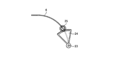
- FIG. 7 is a cross-sectional view showing a drive part of the damper of the first embodiment
- FIG. 8 is a cross-sectional view showing the flow of air in the air passage of the bathroom dryer of the first embodiment.
- FIG. 9 shows the flow of air around the blowing guide grill of the bathroom dryer according to the first embodiment. A to cross section.
- the bathroom dryer 91 includes a circulation air passage 2 a formed in the housing 16 ⁇ / b> A for ventilating, drying, and heating the bathroom, and for ventilating the bathroom. And a ventilation air passage 2 b formed in the exhaust duct connecting member 22.
- the exhaust duct connecting member 22 as a ventilation unit is connected to the ventilation connection port 9 of the circulation air passage 2a.
- the circulation air passage 2a is formed by a housing 16A and a circulation orifice (bottom plate) 17.
- the bathroom air circulation inlet 4 and the circulation outlet (blowout guide grille) 8 are provided downward, and the ventilation connection port is provided upstream on the downstream side.
- 9 is provided, the circulation blower 5 driven by the motor M1 is arranged on the inner upstream side, and the rotary damper 6 and the heating unit 7 are arranged on the inner downstream side.
- the circulation air passage 2a provided with the circulation fan 5, the rotary damper 6, and the heating unit 7 is referred to as a circulation unit 91A.
- the exhaust duct connecting member 22 as a ventilation unit is formed with a ventilation air passage 2b so that the exhaust direction is lateral (the right direction in FIG. 1), and the exhaust port 21 is opened sideways. If an exhaust duct is connected to the exhaust port 21, the bathroom can be ventilated.
- a filter 20 for removing dust in the air is disposed upstream of the circulation suction port 4.
- the lower side of the bathroom dryer 91 is covered with the design panel 14.
- a control unit 15 and a power supply connection unit are arranged on the upper side of the motor M1.
- a remote controller (not shown) is connected to the control unit 15 via a communication line, and the remote controller outputs an operation command to the control unit 15.
- the ventilation connection port 9 is provided on the top plate of the housing 16A, and air flows from the circulation air passage 2a through the ventilation connection port 9 to the ventilation air passage 2b.
- the circulation air passage 2a is formed by a housing 16A and a circulation orifice (bottom plate) 17, and is formed in a box shape in which the circulation suction port 4 and the ventilation connection port 9 are opened downward.
- the ventilation connection port 9 communicates with the ventilation air passage 2b when the rotary damper 6 is opened.
- the housing 16A is provided with a shaft through hole (not shown) for passing the rotation shaft of the drive motor M1. Further, the side plate of the housing 16 ⁇ / b> A is provided with an insertion port for inserting a holding member that holds the heating unit 7 and the rotary damper 6.
- the circulation blower 5 is a single suction sirocco fan blower, and is disposed on the upstream side of the circulation air passage 2 a so as to face the circulation suction port 4.
- the air blown out from the circulation blower 5 is diverted by the rotary damper 6 into the downstream side of the circulation air passage 2 a flowing from the heating unit 7 to the circulation outlet 8 and the ventilation air passage 2 b passing through the ventilation connection port 9.
- the motor M1 is installed on the upper side of the circulation air passage 2a.
- the heating unit 7 includes, for example, a plurality of heat generating elements arranged at intervals, or a plurality of heat dissipating fins provided on the heat generating element to form an air path around the heat generating element or the heat dissipating fins.
- the electric heater is configured to dissipate heat through the air, and the heating element in which the electric insulator and the heat conductor are disposed around the electric heater is housed in a metal pipe.
- the heating unit 7 is disposed on the most downstream side of the circulation air passage 2a.
- a PTC (Positive Temperature Coefficient) heater Since the PTC heater uses a PTC element whose resistance value suddenly rises at a predetermined temperature (Curie temperature) as a heating element, it has a self-temperature control function and is excellent in safety and temperature. Control is unnecessary and low cost.
- the circulation outlet (blowout guide grille) 8 is a rectangular air passage that is contracted (reduced) (an air passage in which the air passage area decreases toward the downstream side). By curving the side plate on the long side of the air passage frame, the air passage area is reduced.
- the blowout guide grill 8 is arranged with a gap at the downstream end of the circulation air passage 2a where the heating unit 7 is arranged, but the air passage area before the reduction is reduced to the circulation air where the heating unit 7 is arranged. It is larger than the air passage area at the downstream end of the passage 2a.
- the gap between the downstream end of the circulation air passage 2 a and the blowout guide grill 8 is an induction flow opening 31 that draws the air around the blowout guide grille 8 into the blowout guide grille 8.
- the attraction opening 31 is oriented in a direction perpendicular to the air blowing direction at the downstream end of the circulation air passage 2a.
- the air passage area of the blowing guide grille 8 is made larger than the air passage area at the downstream end of the circulation air passage 2a, and the induction flow opening 31 is directed in a direction perpendicular to the air blowing direction at the downstream end of the circulation air passage 2a.
- the blowing guide grill 8 has wing plates arranged in parallel, and can direct the blowing air in a certain direction.
- a rotating shaft may be provided in a slat and you may adjust a wind direction by adjusting direction by an adjustment means.
- the rotary damper 6 is disposed on the lower side of the ventilation connection port 9 between the circulation fan 5 and the heating unit 7 in the circulation air passage 2a, and has a plate shape with a flat front end and a base end and a curved middle. Is formed. As shown in FIG. 7, the rotary damper 6 rotates around a damper rotation shaft 23 provided at the base end portion. A fan gear 24 is fixed to the damper rotating shaft 23 and the side portion of the rotary damper 6, and the rotary damper 6 can be rotated by rotating the fan gear 24.
- the rotary damper 6 is driven by a speed reducer that combines a fan gear 24 and a small gear 25.
- the small gear 25 is rotated by, for example, a driving means such as a stepping motor, and the rotary damper 6 is rotated and positioned via the fan-shaped gear 24 to constitute a part of the circulation air path 2a and / or the ventilation air path 2b. To do.
- the rotating damper 6 contacts the top plate of the housing 16A in the clockwise direction to the position where the ventilation connection port 9 is closed, and contacts the circulation orifice (bottom plate) 17 in the counterclockwise direction to contact the circulation air passage 2a. Is closed to the position where the upstream side of the circulation air passage 2a communicates with the ventilation connection port 9, and has a rotatable angle range (about 30 °).
- the rotational position of the rotary damper 6 is determined by rotating the rotary damper 6 clockwise or counterclockwise over the movable angle range and rotating it to the position shown in FIG. 5 or FIG. 2 where the rotation stops. Thereafter, as shown in FIG. 3 or FIG. 4, positioning control is performed to rotate the rotary damper 6 to a position where the upstream side of the circulating air passage 2 a communicates with both the downstream side of the circulating air passage 2 a and the ventilation connection port 9.
- the design panel 14 is attached to the housing 16A or the ceiling so as to cover the exposed portion of the housing 16A in the bathroom.
- the design panel 14 is formed in a flat shape, and is attached with a gap between the ceiling surface and the lower outer edge of the circulation unit 91 ⁇ / b> A and the outer peripheral upward side wall of the design panel 14. Inhale air from the bathroom.
- the design panel 14 By forming the design panel 14 in a flat plate shape, the design panel surface can be easily cleaned.
- the control unit 15 includes a storage element in which a predetermined control program is stored, and individually controls the circulation fan 5, the heating unit 7, and the rotary damper 6 in accordance with an operation command input from the remote controller, thereby drying the bathroom. Let the machine 91 perform ventilation operation, drying operation, and the like.
- the bathroom dryer 91 uses the rotary damper 6 as one-side support by the damper rotating shaft 23 provided at the base end portion, and reduces the rotation angle, thereby circulating the air circulation path 2a.
- the bathroom dryer 91 can be made compact and lightweight. Moreover, it can position and hold
- the tip of the rotary damper 6 swings counterclockwise to a position where it contacts the circulation orifice (bottom plate) 17 and is positioned, and the heating unit 7 side (downstream side) of the circulation air passage 2 a is positioned. ) Is closed, and the circulation air passage 2 a is connected to the ventilation air passage 2 b through the ventilation connection port 9.
- the air in the bathroom in which the bathroom dryer 91 is installed flows through the ventilation inlet 2b through the circulation inlet 4, and is exhausted to the outside through the outlet 21 to ventilate the bathroom.
- the tip of the rotary damper 6 does not contact the top plate of the housing 16A or the circulation orifice (bottom plate) 17, and the top plate of the housing 16A and the circulation orifice (bottom plate) 17 It is positioned at a position close to the top plate of the housing 16A from the intermediate position. Therefore, air can flow from the ventilation connection port 9 to both the ventilation air passage 2b and the air passage downstream of the circulation air passage 2a where the heating unit 7 is disposed. At the same time, the heating unit 7 is energized.
- the tip of the rotary damper 6 does not contact the top plate of the housing 16A or the circulation orifice (bottom plate) 17, and the top plate of the housing 16A and the circulation orifice (bottom plate) 17 It is positioned at a position close to the top plate of the housing 16A from the intermediate position.
- air can flow from the ventilation connection port 9 to both the ventilation air passage 2b and the downstream air circulation passage 2a where the heating unit 7 is disposed.
- the circulating fan 5 is started to operate, and unlike the drying operation, the heating unit 7 is not energized.
- the bathroom air blown out from the circulation blower 5 and flowed into the circulation wind path 2a is blown into the bathroom from the circulation outlet 8 and partly flows into the ventilation wind path 2b from the ventilation connection port 9.
- the air is exhausted from the exhaust port 21 to the outside.
- ventilation is performed while blowing air into the bathroom, and the bathroom can be exhausted.
- the tip of the rotary damper 6 does not contact the top plate of the housing 16A or the circulation orifice (bottom plate) 17, and the top plate and the circulation orifice (bottom plate) 17 of the housing 16A. Is positioned at a position close to the circulation orifice (bottom plate) 17 from the intermediate position. Therefore, air can flow from the ventilation connection port 9 into both the ventilation air passage 2b and the downstream air circulation passage 2a where the heating unit 7 is disposed.
- the circulating fan 5 is started to operate, and unlike the drying operation, the heating unit 7 is not energized.
- the bathroom air flowing into the circulation air passage 2a from the circulation blower 5 is blown into the bathroom from the circulation outlet 8 through the heating unit 7, and a part of the ventilation air is ventilated from the ventilation connection port 9. It flows into the path 2b and is exhausted from the exhaust port 21 to the outside.
- the heating unit 7 is not energized, and thus air is blown into the bathroom with the air temperature in the bathroom. While blowing room temperature air into the bathroom, ventilate and dry the bathroom and clothing.
- the drying speed of the wind drying operation is slower than that of the drying operation, the heating unit 7 is not energized, so that the drying in the bathroom can be performed with low power consumption.
- the rotary damper 6 is rotated to a position in contact with the top plate of the housing 16 ⁇ / b> A to close the ventilation connection port 9 and only downstream of the circulation air passage 2 a leading to the circulation outlet 8. Air can flow into the.
- the circulation fan 5 is started to operate, and the heating unit 7 is energized.
- the bathroom air blown from the circulation blower 5 and flows into the circulation air passage 2a is blown into the bathroom through the heating unit 7.
- the air passing through the heating unit 7 is heated and blown out into the bathroom as warm air so that the bathroom can be heated.
- the design panel 14 is disposed so as to cover the lower surface of the circulation unit 91A with a gap 30 between the ceiling and the lower outer edge of the circulation unit 91A.
- the air is sucked into the circulation fan 5 and flows into the gap space 33 between the design panel 14 and the circulation orifice (bottom plate) 17 from the gap 30.
- the bathroom air that has flowed into the gap space 33 is sucked into the circulation blower 5 from the circulation suction port 4 and blown into the circulation air passage 2a. It flows into the downstream and / or the ventilation air passage 2b.
- the gap 30 is provided over the entire circumference of the design panel 14 and can suck in the air in the bathroom from the entire circumference. Therefore, the back surface of the design panel 14 and the bottom plate 17 can be dried by the flow of wind, and the occurrence of mold on the back surface of the design panel 14 and the bottom plate 17 can be prevented.
- the air blown out from the circulation blower 5 increases the speed when passing through the heating unit 7 and is blown into the bathroom through the blowout guide grille 8.
- the induced flow generated at this time is sucked from the gap 30 and flows into the gap space 33 between the design panel 14 and the circulation orifice (bottom plate) 17, and flows into the air passage of the blowout guide grill 8 from the induced flow opening 31. Then, it is blown into the bathroom together with the air that has passed through the heating unit 7.
- the partition plate 32 that separates the gap space 33 into the circulation suction port 4 side and the blowout guide grille 8 side is provided in the circulation orifice (bottom plate) 17, the circulation suction is performed from the induction flow opening 31 of the blowout guide grille 8. Air does not flow to the mouth 4 side, and the induced flow can be efficiently sucked into the blowing guide grill 8. Since the wind flows around the blowout guide grille 8 due to the occurrence of the induced flow, the generation of mold around the blowout guide grille 8 on the back surface of the design panel 14 can be suppressed.
- the design panel 14 has the gap
- FIG. FIG. 10 is a cross-sectional view showing a second embodiment of the bathroom dryer according to the present invention
- FIG. 11 is a top view of the bathroom dryer according to the second embodiment.
- the bathroom dryer 92 of the second embodiment is different from the bathroom dryer 91 of the first embodiment in that a ventilation unit 92B is used instead of the exhaust duct connecting member 22, and the other room It has a ventilation function.
- the circulation unit 91A and the ventilation unit 92B are separable. Since the circulation unit 91A and the design panel 14 have been described in the bathroom dryer 91 according to the first embodiment, the description thereof is omitted.
- the ventilation unit 92B has a housing 16B, and a ventilation air passage 2b is formed in the housing 16B.
- the ventilation air passage 2b is provided with a bathroom inlet 12a downward on the upstream side, an exhaust outlet 13 on the downstream side, and a ventilation blower (sirocco fan) 11 driven by the motor M2 inside.
- a ventilation orifice 18 provided with a ventilation suction port 10 is disposed on the upstream side of the ventilation blower 11.
- a space between the bathroom inlet 12 a and the ventilation orifice 18 is a ventilation chamber 12.
- the ventilation chamber 12 has an inlet port 12b for another room.
- the bathroom dryer 92 according to the second embodiment can perform a ventilation operation, a drying operation, a wind drying operation, a heating operation, and a cool air operation in the same manner as the bathroom dryer 91 according to the first embodiment.
- the ventilation operation the drying operation, the cool air operation, and the wind drying operation
- the circulation air passage 2a is connected to the ventilation air passage 2b, and the ventilation blower 11 is started to operate.
- the air in the bathroom in which the bathroom dryer 92 is installed flows through the circulation air inlet 2 through the circulation air passage 2a, is guided to the ventilation connection port 9 by the rotary damper 6, and the air in the ventilation air passage 2b.
- the air is sucked into the ventilation chamber 12 through the bathroom suction port 12a.
- the ventilation air passage 2b is provided with a plurality (three) of other-chamber suction ports 12b. If the exhaust duct from other rooms, such as a washroom and a toilet, is connected to each other room inlet 12b and the ventilation blower 11 is operated, ventilation of another room can be performed. Connection ports that are not used can be closed, and the number of rooms to be ventilated can be arbitrarily selected.
- the exhaust connection port 9 communicates with the bathroom suction port 12a of the ventilation chamber 12 and is disposed below the exhaust port 13 because the circulation blower 5 and the ventilation blower 11 are operated at the same time from the circulation air passage 2a to the ventilation air passage. This is to prevent the air from flowing backward to the other-chamber suction port 12b in the drying operation, the wind drying operation, and the cool air operation for blowing air to 2b.
- a backflow prevention damper may be provided in the other chamber suction port 12b.
- the air volume control of both the air blowers is performed so that the air intake air volume of the ventilation air blower 11 becomes larger than the air volume sent from the circulation air blower 5 to the air ventilation path 2b.
- the bathroom dryer according to the present invention is useful as a household or commercial bathroom dryer that performs ventilation, drying, and heating of a bathroom.
Landscapes
- Engineering & Computer Science (AREA)
- Chemical & Material Sciences (AREA)
- Combustion & Propulsion (AREA)
- Mechanical Engineering (AREA)
- General Engineering & Computer Science (AREA)
- Central Heating Systems (AREA)
- Ventilation (AREA)
- Drying Of Solid Materials (AREA)
Abstract
ハウジングと底板により形成され、下向きに循環吸込口及び吹出しガイドグリルが設けられ、上向きに換気接続口が設けられ、内部に、循環送風機、前記換気接続口を開閉するダンパー及び加熱部が配置された循環風路を有し、浴室の天井に設置される循環ユニットと、排気口が設けられた換気風路を有し、前記循環ユニットの換気接続口に接続された換気ユニットと、外縁部が、前記天井及び循環ユニットの下側外縁部との間に間隙を有して前記循環ユニットの下面を覆うように配置された意匠パネルと、前記加熱部が配置された循環風路の下流端と前記吹出しガイドグリルの間に設けられ、周囲の空気を該吹出しグリル内へ誘引する誘引流開口と、を備える。
Description
本発明は、浴室の天井に設置され、浴室を換気、乾燥、暖房する浴室乾燥機に関する。
従来、浴室の空気を換気、乾燥、暖房する浴室乾燥機に関して、多くの提案がなされている。浴室乾燥機は、浴室の天井若しくは側壁上部に設置され、その浴室側は、意匠性及び安全性の向上のためにパネルで覆われている。パネルと浴室乾燥機本体との間の間隙には、浴室の湿気が滞留し易く、カビが発生し易い。そのため、パネル裏のカビ抑制に関しても、種々の提案がなされている。また、空気吹出口の周辺のカビ対策としては、周辺空気の循環を改善する必要があるが、このような空気吹出口の空気循環の改善についても、いくつか提案されている。
多室用の浴室乾燥機は、浴室を換気、乾燥、暖房する機能と、他室を換気する機能との2つの機能を有し、夫々の機能を独立に動作させる場合には、少なくとも2つの風路が必要となる。そのため、多室用の浴室乾燥機は、浴室のみの1室用の浴室乾燥機と比べて大形となり、設置施工性、メンテナンス性が悪い。多室用の浴室乾燥機についても、設置施工性、メンテナンス性の改善のために、種々の提案がなされている。
例えば、特許文献1で提案されている浴室用換気暖房機は、本体開口に向かい合う位置にある下面を有し、この下面側から下面外周枠より内側で天井に向かって突出して前記下面と天井面との間を塞ぐように四角枠状に形成されるルーバー枠に吸込口を設け、この吸込口より浴室内空気を吸込むようにしている。この吸込口を設けることにより、ルーバー枠と天井との間に形成される空間に空気が滞留しないようにすると共に、気流によってルーバー枠の内部空間が乾燥され、カビ発生を抑えることができる。また、ルーバー枠の吸込口から空気を吸込むことにより、浴室中央部へ吹出された空気は、床面にあたり浴室壁面に沿って上昇し、天井に沿って流れて吸込口に吸込まれる循環流となり、浴室空気の循環が改善される。
また、特許文献2で提案されているサウナ装置は、制御装置により運転開始時の送風機の風量を増加させ、浴室空気の循環性を高めて温度分布を均一化し、効率的な加湿を行うと共に、吹出口への結露水付着を抑制している。さらに、ルーバーを設けた吹出口の風路側面に開口を設け、誘引流により風量を増加させている。誘引流により、吹出口周辺の空気を吸込み、吹出口周辺の空気の積極的な循環を促すと共に、風量増加により性能を向上させている。
また、特許文献3で提案されている空気循環装置は、電動ファンから吹出された空気が通る配管先端部にノズルを設け、ノズル先端部に間隙を置いてベンチュリーを設けることにより、風量増加と空調空間の空気循環の改善を図っている。
しかしながら、特許文献1で提案されている浴室乾燥機は、方形のルーバー枠の対向する2側面のみを開口しているので、他の側面に近い内部空間では、空気が滞留しやすい、という問題がある。また、ルーバー枠内の吹出口周辺の内部空間でも、吹出口を形成するための風路が配置されていて、空気が滞留すると考えられる。また、ルーバー下面が曲面となっていて、清掃性が悪い、という問題がある。さらに、浴室全体の空気の循環性については、ルーバー枠の開口面が対向する2側面のみであるため、開口していない側面の周囲の空気の循環性が悪い、という問題がある。
また、特許文献2に記載されたサウナ装置は、制御装置により送風機を制御して風量を増加させるので、騒音が大きくなる、という問題がある。また、誘引流を利用するものでは、吹出口の枠のうち、送風機の吸込口がある側の側面には、空気のショートサーキットが発生するため、開口を設けることができず、その側面の周囲の空気の循環性を改善するできないことと、得られる誘引流が少ない、という問題がある。
特許文献3に記載された空気循環装置は、誘引流を発生させるためにノズルを設けており、空気吹出し部にノズル設置のための大きな空間が必要となる。また、ノズル設置のためにコストが増加する、という問題がある。
本発明は、上記に鑑みてなされたものであり、意匠パネルの裏側と循環ユニットの底板に発生するカビを抑制することができ、小形、低騒音で吹出し風量を増加させることができ、浴室空気の循環性を向上して、浴室床面の温度分布を改善し、乾燥ムラを改善することができる浴室乾燥機を得ることを目的とする。
上述した課題を解決し、目的を達成するために、本発明は、ハウジングと底板により形成され、下向きに循環吸込口及び吹出しガイドグリルが設けられ、上向きに換気接続口が設けられ、内部に、循環送風機、前記換気接続口を開閉するダンパー及び加熱部が配置された循環風路を有し、浴室の天井に設置される循環ユニットと、排気口が設けられた換気風路を有し、前記循環ユニットの換気接続口に接続された換気ユニットと、外縁部が、前記天井及び循環ユニットの下側外縁部との間に間隙を有して前記循環ユニットの下面を覆うように配置された意匠パネルと、前記加熱部が配置された循環風路の下流端と前記吹出しガイドグリルの間に設けられ、周囲の空気を該吹出しグリル内へ誘引する誘引流開口と、を備えることを特徴とする。
本発明の浴室乾燥機は、浴室空気の循環吸込口を含む循環ユニットの下面を、間隙を隔てて意匠パネルで覆ったので、意匠パネルの裏側の隙間空間の空気が循環吸込口から吸込まれ、意匠パネル裏側の空気の滞留が低減される。また、吸込み気流により、意匠パネル裏側及び循環ユニットの底板が乾燥され、カビの発生を抑制することができる。また、吹出しグリル内へ誘引される誘引流により、吹出しグリルの周辺も空気の循環を促進し、カビの発生を抑制することができる。
また、意匠パネルの外縁部全周から浴室空気を吸込むので、浴室空気の循環性が良く、誘引流を利用して低騒音で吹出し風量を増加させ、浴室床面温度分布と浴室の乾燥ムラを改善している。
実施の形態の浴室乾燥機は、換気、乾燥、涼風、風乾燥及び暖房の5つの運転モードを有し、リモートコントローラにより運転モードを切替えることができる。また、多室用の浴室乾燥機では、上記の運転と同時に、浴室とは別の他室の換気を行うことができる。
換気運転では、1室用の浴室乾燥機の場合は、循環送風機を運転して浴室の空気を外部へ排気する。多室用の浴室乾燥機の場合は、換気送風機を運転して、浴室と他室の両方の空気を外部へ排気する。
乾燥運転では、循環送風機を運転して浴室から吸込んだ空気を、ダンパーにより循環側と換気側に分流し、循環側に分流された空気を、加熱部で加熱して浴室内に温風送風すると共に、換気側に分流された浴室の空気を外部へ排気して浴室内の乾燥を行う。このとき、換気風量よりも循環風量の方が多くなるように、ダンパーの開度を調整する。多室用の浴室乾燥機の場合は、換気送風機を運転して、浴室と他室の両方の空気を外部へ排気する。
涼風運転では、循環送風機を運転して浴室から吸込んだ空気を、ダンパーにより循環側と換気側に分流し、循環側に分流された空気を浴室内に送風すると共に、換気側に分流された浴室の空気を外部へ排気して排熱を行う。涼風運転では、加熱部での加熱を行わず、循環空気は、常温のまま浴室内へ送風される。このとき、換気風量よりも循環風量の方が多くなるように、ダンパーの開度を調整する。多室用の浴室乾燥機の場合は、換気送風機を運転して、浴室と他室の両方の空気を外部へ排気する。
風乾燥運転では、循環送風機を運転して浴室から吸込んだ空気を、ダンパーにより循環側と換気側に分流し、循環側に分流された空気を浴室内に送風すると共に、換気側に分流された浴室の空気を外部へ排気して浴室の乾燥を行う。このとき、循環風量よりも換気風量の方が多くなるように、ダンパーの開度を調整する。多室用の浴室乾燥機の場合は、換気送風機を運転して、浴室と他室の両方の空気を外部へ排気する。風乾燥運転は、乾燥運転とは異なり、温風を用いずに送風と換気で浴室の乾燥を行う。通常の乾燥運転に比べ乾燥時間はかかるが、省エネルギーである。
暖房運転では、循環送風機を運転して浴室から吸込んだ空気を、ダンパーにより循環側に流し、加熱部で加熱して浴室内へ送風し暖房を行う。1室用の浴室乾燥機の場合は、暖房時、換気機能は停止するが、多室用の浴室乾燥機の場合は、換気送風機を運転すれば他室換気を行なうことができる。
上記の5つの運転モードで運転するためには、循環風路内に風路を4つ形成する必要があり、ダンパーとしての回転ダンパーの回転(搖動)位置により、各風路を形成するようにした。各運転モードにおける回転ダンパーの回転位置、風路形成については、実施の形態の説明で詳細を説明する。
以下に、本発明に係る浴室乾燥機の実施の形態を図面に基づいて詳細に説明する。なお、この実施の形態によりこの発明が限定されるものではない。
実施の形態1.
図1は、本発明に係る浴室乾燥機の実施の形態1を示す断面図であり、図2は、ダンパーの回転位置を換気位置としたときの循環風路の下流側を示す断面図であり、図3は、ダンパーの回転位置を乾燥、涼風位置としたときの循環風路の下流側を示す断面図であり、図4は、ダンパーの回転位置を風乾燥位置としたときの循環風路の下流側を示す断面図であり、図5は、ダンパーの回転位置を暖房位置としたときの循環風路の下流側を示す断面図であり、図6は、実施の形態1の吹出しガイドグリルを示す斜視図であり、図7は、実施の形態1のダンパーの駆動部を示す断面図であり、図8は、実施の形態1の浴室乾燥機の風路の空気の流れ示す断面図であり、図9は、実施の形態1の浴室乾燥機の吹出しガイドグリルの周囲の空気の流れを示す断面図である。
図1は、本発明に係る浴室乾燥機の実施の形態1を示す断面図であり、図2は、ダンパーの回転位置を換気位置としたときの循環風路の下流側を示す断面図であり、図3は、ダンパーの回転位置を乾燥、涼風位置としたときの循環風路の下流側を示す断面図であり、図4は、ダンパーの回転位置を風乾燥位置としたときの循環風路の下流側を示す断面図であり、図5は、ダンパーの回転位置を暖房位置としたときの循環風路の下流側を示す断面図であり、図6は、実施の形態1の吹出しガイドグリルを示す斜視図であり、図7は、実施の形態1のダンパーの駆動部を示す断面図であり、図8は、実施の形態1の浴室乾燥機の風路の空気の流れ示す断面図であり、図9は、実施の形態1の浴室乾燥機の吹出しガイドグリルの周囲の空気の流れを示す断面図である。
図1に示すように、実施の形態1の浴室乾燥機91は、ハウジング16A内に形成された、浴室の換気、乾燥、暖房を行うための循環風路2aと、浴室の換気を行なうための排気ダクト接続部材22に形成された換気風路2bと、を有している。換気ユニットとしての排気ダクト接続部材22は、循環風路2aの換気接続口9に接続されている。
循環風路2aは、ハウジング16Aと循環オリフィス(底板)17により形成され、下向きに浴室空気の循環吸込口4及び循環吹出口(吹出しガイドグリル)8が設けられ、下流側に上向きに換気接続口9が設けられ、内部上流側にモータM1により駆動される循環送風機5が配置され、内部下流側に回転ダンパー6及び加熱部7が配置されている。循環送風機5、回転ダンパー6及び加熱部7を備えた循環風路2aを循環ユニット91Aと呼ぶ。
換気ユニットとしての排気ダクト接続部材22は、排気方向が側方(図1の右方向)となるように換気風路2bが形成され、横向きに排気口21が開口している。排気口21に排気ダクトを接続すれば、浴室の換気を行うことができる。
循環吸込口4の上流側には、空気中の埃を取除くフィルター20が配置されている。浴室乾燥機91の下側は、意匠パネル14で覆われている。モータM1の上側には、制御部15及び電源接続部(図示せず)が配置されている。制御部15には、通信線を介してリモートコントローラ(図示せず)が接続され、リモートコントローラは、制御部15に対して運転指令を出力する。
換気接続口9は、ハウジング16Aの天板に設けられていて、循環風路2aから換気接続口9を通して換気風路2bに空気が流れるようになっている。循環風路2aは、ハウジング16A及び循環オリフィス(底板)17により形成され、循環吸込口4及び換気接続口9が下向きに開口する箱状に形成されている。換気接続口9は、回転ダンパー6が開くと、換気風路2bに連通する。ハウジング16Aには、駆動モータM1の回転軸を通すための軸通し孔(図示せず)が設けられている。また、ハウジング16Aの側板には、加熱部7及び回転ダンパー6を保持する保持部材を挿入するための挿入口が設けられている。
循環送風機5は、片吸込式のシロッコファン送風機であり、循環吸込口4に対向するように、循環風路2aの上流側に配置されている。循環送風機5から吹出された空気は、回転ダンパー6により、加熱部7から循環吹出口8へ流れる循環風路2aの下流側と、換気接続口9を通る換気風路2bとに分流される。モータM1は、循環風路2aの上側に設置されている。
加熱部7は、例えば、複数の発熱体を間隔をあけて配置したり、発熱体に複数の放熱フィンを設けたりして、発熱体又は放熱フィンの周囲に風路を形成し、該風路に空気を通して放熱するようにした電気ヒータや、周囲に電気絶縁体及び熱伝導体が配置された発熱体を、金属パイプの中に収めた電気ヒータ等により構成される。
加熱部7は、循環風路2aの最下流に配置されている。加熱部7の過加熱を抑えるために、PTC(Positive Temperature Coefficient;自己温度制御性)ヒータを用いるのがよい。PTCヒータは、所定の温度(キュリー温度)になると急激に抵抗値が上昇するPTC素子を発熱体として用いているため、自己温度制御機能を有しており、安全性に優れていると共に、温度制御が不要で低コストである。
循環吹出口(吹出しガイドグリル)8は、図6に示すように、矩形の縮管(縮小)する風路(風路面積が下流側ほど減少する風路)となっている。風路枠の長辺側の側板を湾曲させることにより、風路面積を縮小させている。吹出しガイドグリル8は、加熱部7が配置された循環風路2aの下流端に間隙を開けて配置されているが、縮小される前の風路面積を、加熱部7が配置された循環風路2aの下流端の風路面積よりも大きくしている。
循環風路2aの下流端と吹出しガイドグリル8の間の間隙は、吹出しガイドグリル8の周囲の空気を吹出しガイドグリル8内へ誘引する誘引流開口31となっている。誘引流開口31は、循環風路2aの下流端の空気吹出し方向に対して垂直方向を向いている。吹出しガイドグリル8の風路面積を、循環風路2aの下流端の風路面積よりも大きくし、誘引流開口31を、循環風路2aの下流端の空気吹出し方向に対して垂直方向に向けることにより、ノズルを設けることなく、誘引流を効率よく発生させることができる。
さらに、吹出しガイドグリル8は、並列配置された羽板を有し、吹出空気を一定の方向に向けることができる。なお、羽板に回転軸を設け、調節手段により向きを調節して風向を調節してもよい。
回転ダンパー6は、循環風路2a内の循環送風機5と加熱部7との間の換気接続口9の下側に配置され、先端部及び基端部が平らで中間部が湾曲した板状に形成されている。図7に示すように、回転ダンパー6は、基端部に設けられたダンパー回転軸23回りに回動する。扇状歯車24が、回転ダンパー6のダンパー回転軸23及び側部に固定されており、扇状歯車24を回動させることにより、回転ダンパー6を回動させることができる。
回転ダンパー6は、扇状歯車24と小歯車25を組合わせた減速機により駆動される。小歯車25を、例えば、ステッピングモータのような駆動手段により回転させ、扇状歯車24を介して回転ダンパー6を回動、位置決めし、循環風路2a及び/又は換気風路2bの一部を構成する。
回転ダンパー6は、時計回りには、ハウジング16Aの天板に接触して換気接続口9を閉じる位置まで、また、反時計回りには、循環オリフィス(底板)17に接触して循環風路2aの下流側を閉じ、循環風路2aの上流側を換気接続口9に連通させる位置まで回動可能であり、回動可能な角度範囲(約30°)を有している。
回転ダンパー6の回動位置決めは、回転ダンパー6を、時計回り若しくは反時計周りに可動角度範囲以上回動させ、回動が止まる図5若しくは図2に示す位置まで回動させて始点を決めた後、図3若しくは図4に示す、循環風路2aの上流側を循環風路2aの下流側及び換気接続口9の両方に連通させる位置まで、回転ダンパー6を回動させる位置決め制御により行う。
意匠パネル14は、ハウジング16Aの浴室内露出部を覆うように、ハウジング16A又は天井に取付けられる。意匠パネル14は、フラットに形成されていて、天井面及び循環ユニット91Aの下側外縁部と、意匠パネル14の外周上向き側壁との間に間隙を開けて取付け、意匠パネル14全周に亘る間隙から浴室空気を吸込む。意匠パネル14を平板状に形成することにより、意匠パネル表面の清掃がし易い。
制御部15は、所定の制御プログラムが格納された記憶素子を備え、リモートコントローラから入力された運転指令に応じて、循環送風機5、加熱部7及び回転ダンパー6を夫々個別に制御し、浴室乾燥機91に換気運転、乾燥運転等を行わせる。
以上説明したように、実施の形態1の浴室乾燥機91は、回転ダンパー6を基端部に設けられたダンパー回転軸23による片側支持とし、回動角度を小さくすることにより、循環風路2aの高さを抑えることができ、浴室乾燥機91をコンパクト化、軽量化することができる。また、回転角度範囲の中間位置で位置決め、保持することができ、循環風量と換気風量を調節することができる。
次に、図2~図5を参照して、実施の形態1の浴室乾燥機91の換気運転、乾燥運転、涼風運転、風乾燥運転及び暖房運転について説明する。図2に示すように、換気運転では、回転ダンパー6の先端が循環オリフィス(底板)17に接触する位置まで反時計回りに搖動し、位置決めされ、循環風路2aの加熱部7側(下流側)が塞がれ、換気接続口9を通して換気風路2bへ循環風路2aが繋がる。
浴室乾燥機91が設置されている浴室の空気は、循環吸込口4を通って換気風路2b内を流れ、排気口21から外部へ排気され、浴室が換気される。
乾燥運転では、図3に示すように、回転ダンパー6の先端は、ハウジング16Aの天板にも循環オリフィス(底板)17にも接触せず、ハウジング16Aの天板と循環オリフィス(底板)17の中間位置からハウジング16Aの天板に近い位置に位置決めされる。それ故、換気接続口9から換気風路2b、加熱部7が配置された循環風路2aの下流側、の両方の風路へ空気が流入可能となる。同時に、加熱部7は通電される。
乾燥運転では、循環送風機5から吹出されて循環風路2aに流入した浴室空気は、加熱部7を通って、循環吹出口8から浴室内に吹出されると共に、一部が、換気接続口9を通って換気風路2bへ流入し、排気口21から外部へ排気される。乾燥運転では、浴室内へ温風を吹出しながら換気を行なって、浴室や衣類を乾燥することができ、浴室乾燥機91を温風乾燥機として機能させることができる。
涼風運転では、図3に示すように、回転ダンパー6の先端は、ハウジング16Aの天板にも循環オリフィス(底板)17にも接触せず、ハウジング16Aの天板と循環オリフィス(底板)17の中間位置からハウジング16Aの天板に近い位置に位置決めされる。その結果、換気接続口9から換気風路2b、加熱部7が配置された循環風路2aの下流、の両方の風路へ空気が流入可能となる。同時に、循環送風機5が運転開始され、乾燥運転と異なり、加熱部7は通電されない。
涼風運転では、循環送風機5から吹出されて循環風路2aに流入した浴室空気は、循環吹出口8から浴室内に吹出されると共に、一部が換気接続口9から換気風路2bへ流入し、排気口21から外部へ排気される。涼風運転では、浴室内へ送風しながら換気を行い、浴室の排熱を行うことができる。
風乾燥運転では、図4に示すように、回転ダンパー6の先端は、ハウジング16Aの天板にも循環オリフィス(底板)17にも接触せず、ハウジング16Aの天板と循環オリフィス(底板)17の中間位置から循環オリフィス(底板)17に近い位置に位置決めされる。それ故、換気接続口9から換気風路2b、加熱部7が配置された循環風路2aの下流、の両方の風路へ空気が流入可能となる。同時に、循環送風機5が運転開始され、乾燥運転と異なり、加熱部7は通電されない。
風乾燥運転では、循環送風機5から循環風路2aに流入した浴室内空気は、加熱部7を通って循環吹出口8から浴室内に吹出されると共に、一部が換気接続口9から換気風路2bへ流入し、排気口21から外部へ排気される。風乾燥運転では、乾燥運転とは異なり、加熱部7は通電されないので、浴室内空気温度のまま、浴室内へ空気が吹出される。浴室に常温の風を送風すると共に、換気を行って浴室や衣類を乾燥する。風乾燥運転は、乾燥運転に比べて乾燥速度は遅いが、加熱部7は通電されないので、小さな消費電力で浴室内の乾燥を行うことができる。
暖房運転では、図5に示すように、回転ダンパー6を、ハウジング16Aの天板に接触する位置まで回動させて換気接続口9を塞ぎ、循環吹出口8へ続く循環風路2aの下流のみに空気が流入可能となる。同時に、循環送風機5が運転開始され、加熱部7は通電される。
暖房運転では、循環送風機5から吹出されて循環風路2aに流入した浴室空気は、加熱部7を通って浴室内に吹出される。加熱部7を通る空気は加熱され、温風として浴室内へ吹出され、浴室内の暖房を行うことができる。
次に、実施の形態1の浴室乾燥機91の吸込空気の流れについて説明する。図1及び図8に示すように、意匠パネル14は、天井及び循環ユニット91Aの下側外縁部との間に間隙30を有して循環ユニット91Aの下面を覆うように配置されており、浴室の空気は、循環送風機5に吸引され、間隙30から、意匠パネル14と循環オリフィス(底板)17との間の隙間空間33に流入する。隙間空間33に流入した浴室の空気は、循環吸込口4から循環送風機5に吸込まれて循環風路2a内へ吹出され、各運転モードにおける回転ダンパー6の回動位置により、循環風路2aの下流及び/又は換気風路2bへ流入する。間隙30は、意匠パネル14の全周に亘って設けられており、全周から浴室の空気を吸込むことができる。そのため、意匠パネル14の背面及び底板17を風の流れによって乾燥させ、意匠パネル14背面及び底板17のカビの発生を防ぐことができる。
次に、図9を参照して、乾燥運転時、涼風運転時、風乾燥運転時及び暖房運転時の誘引流について説明する。循環送風機5から吹出された空気は、加熱部7を通過するときに速度を上げ、吹出しガイドグリル8を通って浴室内へ送風される。このとき発生する誘引流は、間隙30から吸込まれ、意匠パネル14と循環オリフィス(底板)17との間の隙間空間33へ流入し、誘引流開口31から吹出しガイドグリル8の風路内に流入し、加熱部7を通ってきた空気とともに浴室内へ送風される。
また、隙間空間33を循環吸込口4側と吹出しガイドグリル8側とに分離する仕切板32を、循環オリフィス(底板)17に設けているので、吹出しガイドグリル8の誘引流開口31から循環吸込口4側へ空気が流れることがなく、効率良く誘引流を吹出しガイドグリル8内に吸込むことができる。誘引流の発生により、吹出しガイドグリル8の周囲に風が流れるため、意匠パネル14の背面の吹出しガイドグリル8の周囲のカビの発生を抑制することができる。
また、誘引流により浴室内への送風量が増加するため、暖房運転時の浴室床面温度分布が改善される。また、風量増加により、乾燥、風乾燥運転時の浴室内の乾燥ムラも改善される。また、意匠パネル14は、天井との間に全周に亘る間隙30を有しているので、天井面の空気の循環が良く、天井面の乾燥性が高い。
実施の形態2.
図10は、本発明に係る浴室乾燥機の実施の形態2を示す断面図であり、図11は、実施の形態2の浴室乾燥機の上面図である。図10に示すように、実施の形態2の浴室乾燥機92が、実施の形態1の浴室乾燥機91と異なるところは、排気ダクト接続部材22の替わりに、換気ユニット92Bが用いられ、他室換気機能を有していることである。循環ユニット91Aと換気ユニット92Bは、分離可能である。循環ユニット91A及び意匠パネル14は、実施の形態1の浴室乾燥機91で説明したので、説明を省略する。
図10は、本発明に係る浴室乾燥機の実施の形態2を示す断面図であり、図11は、実施の形態2の浴室乾燥機の上面図である。図10に示すように、実施の形態2の浴室乾燥機92が、実施の形態1の浴室乾燥機91と異なるところは、排気ダクト接続部材22の替わりに、換気ユニット92Bが用いられ、他室換気機能を有していることである。循環ユニット91Aと換気ユニット92Bは、分離可能である。循環ユニット91A及び意匠パネル14は、実施の形態1の浴室乾燥機91で説明したので、説明を省略する。
換気ユニット92Bは、ハウジング16Bを有し、ハウジング16B内に換気風路2bが形成されている。換気風路2bは、上流側に下向きに浴室吸入口12aが設けられ、下流側に横向きに排気口13が設けられ、内部に、モータM2により駆動される換気送風機(シロッコファン)11が配置されている。また、換気送風機11の上流側には、換気吸込口10が設けられた換気オリフィス18が配置されている。浴室吸込口12aと換気オリフィス18の間のスペースは、換気チャンバー12となっている。換気チャンバー12には、他室吸込口12bが開口している。
実施の形態2の浴室乾燥機92は、実施の形態1の浴室乾燥機91と同様に、換気運転、乾燥運転、風乾燥運転、暖房運転及び涼風運転を行うことが可能である。換気運転、乾燥運転、涼風運転及び風乾燥運転では、循環風路2aが換気風路2bに繋がると共に、換気送風機11が運転開始される。その結果、浴室乾燥機92が設置されている浴室の空気は、循環吸込口4を通って循環風路2a内を流れ、回転ダンパー6により換気接続口9へと導かれ、換気風路2bの浴室吸込口12aを通って換気チャンバー12へ吸込まれる。また、浴室以外の他室の空気も他室吸込口12bから換気チャンバー12へ吸込まれ、浴室空気と他室空気は、換気吸込口10から換気送風機11に吸込まれ、排気口13から排気される。これにより、浴室及び他室が換気される。
次に、図10及び図11を参照して、浴室乾燥機92の多室換気機能について説明する。図11に示すように、換気風路2bには、他室吸込口12bが複数個(3個)設けられている。夫々の他室吸込口12bに、洗面所、トイレ等の他室からの排気用ダクトを接続し、換気送風機11を動作させれば、他室の換気を行うことができる。使用しない接続口は、閉塞することができ、換気を行う室数を、任意に選択可能である。
排気接続口9を、換気チャンバー12の浴室吸込口12aに連通させると共に、排気口13の下方に配置するのは、循環送風機5と換気送風機11を同時に運転して循環風路2aから換気風路2bへ送風する乾燥運転、風乾燥運転及び涼風運転において、他室吸込口12bへ空気が逆流するのを防ぐためである。他室吸込口12bへの空気の逆流を確実に防止するために、他室吸込口12bに逆流防止ダンパーを設けてもよい。また、循環送風機5が換気風路2bへ送り込む風量よりも換気送風機11の吸込み風量が大きくなるように、両送風機の風量制御を行なう。
換気ダクトから他室吸込口12bを通って換気チャンバー12へ流入した他室空気は、換気吸込口10を通り、換気送風機11に吸込まれて、外部へと排気される。浴室乾燥機92が停止のときは、図5に示すように、回転ダンパー6を換気接続口9を塞ぐ位置にすれば、他室のみを換気することが可能である。
以上のように、本発明にかかる浴室乾燥機は、浴室の換気、乾燥、暖房を行う、家庭用又は業務用の浴室乾燥機として有用である。
2a 循環風路
2b 換気風路
4 循環吸込口
5 循環送風機
6 回転ダンパー
7 加熱部
8 循環吹出口(吹出しガイドグリル)
9 換気接続口
10 換気吸込口
11 換気送風機
12 換気チャンバー
12a 浴室吸込口
12b 他室吸込口
13 排気口
14 意匠パネル
15 制御部
16A、16B ハウジング
17 循環オリフィス(底板)
18 換気オリフィス
20 フィルター
21 排気口
22 排気ダクト接続部材(換気ユニット)
23 ダンパー回転軸
24 扇状歯車
25 小歯車
30 間隙
31 誘引流開口
32 仕切板
33 隙間空間
M1、M2 モータ
91、92 浴室乾燥機
91A 循環ユニット
92B 換気ユニット
2b 換気風路
4 循環吸込口
5 循環送風機
6 回転ダンパー
7 加熱部
8 循環吹出口(吹出しガイドグリル)
9 換気接続口
10 換気吸込口
11 換気送風機
12 換気チャンバー
12a 浴室吸込口
12b 他室吸込口
13 排気口
14 意匠パネル
15 制御部
16A、16B ハウジング
17 循環オリフィス(底板)
18 換気オリフィス
20 フィルター
21 排気口
22 排気ダクト接続部材(換気ユニット)
23 ダンパー回転軸
24 扇状歯車
25 小歯車
30 間隙
31 誘引流開口
32 仕切板
33 隙間空間
M1、M2 モータ
91、92 浴室乾燥機
91A 循環ユニット
92B 換気ユニット
Claims (6)
- ハウジングと底板により形成され、下向きに循環吸込口及び吹出しガイドグリルが設けられ、上向きに換気接続口が設けられ、内部に、循環送風機、前記換気接続口を開閉するダンパー及び加熱部が配置された循環風路を有し、浴室の天井に設置される循環ユニットと、
排気口が設けられた換気風路を有し、前記循環ユニットの換気接続口に接続された換気ユニットと、
外縁部が、前記天井及び循環ユニットの下側外縁部との間に間隙を有して前記循環ユニットの下面を覆うように配置された意匠パネルと、
前記加熱部が配置された循環風路の下流端と前記吹出しガイドグリルの間に設けられ、周囲の空気を該吹出しグリル内へ誘引する誘引流開口と、
を備えることを特徴とする浴室乾燥機。 - 前記吹出しガイドグリルは、風路面積が、前記循環風路の加熱部が配置された下流端の風路面積より大きく、かつ、下流側ほど風路面積が減少することを特徴とする請求項1に記載の浴室乾燥機。
- 前記誘引流開口は、前記循環風路の下流端の空気吹出方向に対して垂直方向を向いていることを特徴とする請求項1に記載の浴室乾燥機。
- 前記循環ユニットの底板と前記意匠パネルとの間の空間を、前記循環吸込口側と吹出しガイドグリル側とに分離する仕切板を、前記底板に設けたことを特徴とする請求項1に記載の浴室乾燥機。
- 前記意匠パネルは、平板状に形成されていることを特徴とする請求項1に記載の浴室乾燥機。
- 前記換気ユニットの換気風路には、浴室以外の他室から空気を吸込む複数の他室吸込口が設けられ、内部に換気送風機が配置されていることを特徴とする請求項1に記載の浴室乾燥機。
Priority Applications (5)
| Application Number | Priority Date | Filing Date | Title |
|---|---|---|---|
| CN201180060891.4A CN103261803B (zh) | 2011-03-23 | 2011-03-23 | 浴室干燥机 |
| PCT/JP2011/057045 WO2012127663A1 (ja) | 2011-03-23 | 2011-03-23 | 浴室乾燥機 |
| JP2013505732A JP5460921B2 (ja) | 2011-03-23 | 2011-03-23 | 浴室乾燥機 |
| HK13113815.1A HK1186515B (en) | 2011-03-23 | Bathroom dryer | |
| TW100128647A TWI439648B (zh) | 2011-03-23 | 2011-08-11 | Bathroom dryer |
Applications Claiming Priority (1)
| Application Number | Priority Date | Filing Date | Title |
|---|---|---|---|
| PCT/JP2011/057045 WO2012127663A1 (ja) | 2011-03-23 | 2011-03-23 | 浴室乾燥機 |
Publications (1)
| Publication Number | Publication Date |
|---|---|
| WO2012127663A1 true WO2012127663A1 (ja) | 2012-09-27 |
Family
ID=46878856
Family Applications (1)
| Application Number | Title | Priority Date | Filing Date |
|---|---|---|---|
| PCT/JP2011/057045 Ceased WO2012127663A1 (ja) | 2011-03-23 | 2011-03-23 | 浴室乾燥機 |
Country Status (4)
| Country | Link |
|---|---|
| JP (1) | JP5460921B2 (ja) |
| CN (1) | CN103261803B (ja) |
| TW (1) | TWI439648B (ja) |
| WO (1) | WO2012127663A1 (ja) |
Cited By (3)
| Publication number | Priority date | Publication date | Assignee | Title |
|---|---|---|---|---|
| JP2017180891A (ja) * | 2016-03-29 | 2017-10-05 | Toto株式会社 | 浴室換気乾燥装置 |
| WO2019012634A1 (ja) * | 2017-07-12 | 2019-01-17 | 三菱電機株式会社 | 浴室乾燥機 |
| JP2019199859A (ja) * | 2018-05-18 | 2019-11-21 | マックス株式会社 | 送風装置 |
Families Citing this family (12)
| Publication number | Priority date | Publication date | Assignee | Title |
|---|---|---|---|---|
| JP6229154B2 (ja) * | 2013-09-26 | 2017-11-15 | パナソニックIpマネジメント株式会社 | 換気装置 |
| JP2015183982A (ja) * | 2014-03-26 | 2015-10-22 | パナソニックIpマネジメント株式会社 | 換気装置 |
| KR102542121B1 (ko) * | 2016-12-06 | 2023-06-09 | 엘지전자 주식회사 | 욕실관리기 |
| JP6641507B2 (ja) * | 2017-01-26 | 2020-02-05 | 三菱電機株式会社 | 浴室乾燥機 |
| CN112888908B (zh) * | 2018-10-19 | 2023-02-14 | 三菱电机株式会社 | 浴室干燥机 |
| CN112555965A (zh) * | 2019-09-10 | 2021-03-26 | 王旭 | 一种采暖式型材踢脚线板 |
| CN110715384B (zh) * | 2019-11-08 | 2021-04-20 | 泰州左岸信息科技有限公司 | 一种独栋别墅卫生间使用的高效率通风装置 |
| KR102324049B1 (ko) * | 2020-02-07 | 2021-11-08 | 일리노이즈 툴 워크스 인코포레이티드 | 디퓨전 기능을 갖는 에어벤트 |
| US20210348770A1 (en) * | 2020-05-07 | 2021-11-11 | Bsh Home Appliances Corporation | Kitchen ventilation system |
| CN115726436A (zh) * | 2021-08-27 | 2023-03-03 | Toto株式会社 | 浴室系统 |
| KR102471613B1 (ko) * | 2022-06-02 | 2022-11-29 | (주)유원기술 | 듀얼 댐퍼 유닛을 갖는 환기장치 |
| KR102476322B1 (ko) * | 2022-06-02 | 2022-12-13 | (주)유원기술 | 듀얼 댐퍼 유닛을 갖는 환기장치의 제어방법 |
Citations (9)
| Publication number | Priority date | Publication date | Assignee | Title |
|---|---|---|---|---|
| JPS51140351A (en) * | 1975-05-30 | 1976-12-03 | Takasago Thermal Eng Co Lts | Spot air conditioning method |
| JPH0519845U (ja) * | 1991-08-20 | 1993-03-12 | 株式会社大氣社 | 混合型吹き出し装置 |
| JPH07145976A (ja) * | 1993-11-26 | 1995-06-06 | Matsushita Seiko Co Ltd | 害虫除去機能付き換気装置 |
| JP2003207176A (ja) * | 2002-01-11 | 2003-07-25 | Max Co Ltd | 浴室換気装置 |
| JP2004184050A (ja) * | 2002-12-06 | 2004-07-02 | Matsushita Ecology Systems Co Ltd | 浴室の乾燥方法及び浴室乾燥装置 |
| JP2006275408A (ja) * | 2005-03-29 | 2006-10-12 | Toshiba Kyaria Kk | 浴室換気乾燥機 |
| JP2007024404A (ja) * | 2005-07-15 | 2007-02-01 | Max Co Ltd | 空調装置 |
| JP2007071402A (ja) * | 2005-09-02 | 2007-03-22 | Max Co Ltd | 空調装置 |
| JP2008264559A (ja) * | 2008-05-07 | 2008-11-06 | Max Co Ltd | 浴室空調装置 |
Family Cites Families (1)
| Publication number | Priority date | Publication date | Assignee | Title |
|---|---|---|---|---|
| CN2528435Y (zh) * | 2001-12-30 | 2003-01-01 | 北京恩必胜科技发展有限公司 | 远红外低温桑拿浴室加热干燥器 |
-
2011
- 2011-03-23 CN CN201180060891.4A patent/CN103261803B/zh not_active Expired - Fee Related
- 2011-03-23 WO PCT/JP2011/057045 patent/WO2012127663A1/ja not_active Ceased
- 2011-03-23 JP JP2013505732A patent/JP5460921B2/ja active Active
- 2011-08-11 TW TW100128647A patent/TWI439648B/zh not_active IP Right Cessation
Patent Citations (9)
| Publication number | Priority date | Publication date | Assignee | Title |
|---|---|---|---|---|
| JPS51140351A (en) * | 1975-05-30 | 1976-12-03 | Takasago Thermal Eng Co Lts | Spot air conditioning method |
| JPH0519845U (ja) * | 1991-08-20 | 1993-03-12 | 株式会社大氣社 | 混合型吹き出し装置 |
| JPH07145976A (ja) * | 1993-11-26 | 1995-06-06 | Matsushita Seiko Co Ltd | 害虫除去機能付き換気装置 |
| JP2003207176A (ja) * | 2002-01-11 | 2003-07-25 | Max Co Ltd | 浴室換気装置 |
| JP2004184050A (ja) * | 2002-12-06 | 2004-07-02 | Matsushita Ecology Systems Co Ltd | 浴室の乾燥方法及び浴室乾燥装置 |
| JP2006275408A (ja) * | 2005-03-29 | 2006-10-12 | Toshiba Kyaria Kk | 浴室換気乾燥機 |
| JP2007024404A (ja) * | 2005-07-15 | 2007-02-01 | Max Co Ltd | 空調装置 |
| JP2007071402A (ja) * | 2005-09-02 | 2007-03-22 | Max Co Ltd | 空調装置 |
| JP2008264559A (ja) * | 2008-05-07 | 2008-11-06 | Max Co Ltd | 浴室空調装置 |
Cited By (7)
| Publication number | Priority date | Publication date | Assignee | Title |
|---|---|---|---|---|
| JP2017180891A (ja) * | 2016-03-29 | 2017-10-05 | Toto株式会社 | 浴室換気乾燥装置 |
| WO2019012634A1 (ja) * | 2017-07-12 | 2019-01-17 | 三菱電機株式会社 | 浴室乾燥機 |
| TWI668395B (zh) * | 2017-07-12 | 2019-08-11 | 日商三菱電機股份有限公司 | Bathroom dryer |
| JPWO2019012634A1 (ja) * | 2017-07-12 | 2019-11-07 | 三菱電機株式会社 | 浴室乾燥機 |
| CN110832263A (zh) * | 2017-07-12 | 2020-02-21 | 三菱电机株式会社 | 浴室干燥机 |
| JP2019199859A (ja) * | 2018-05-18 | 2019-11-21 | マックス株式会社 | 送風装置 |
| JP7067257B2 (ja) | 2018-05-18 | 2022-05-16 | マックス株式会社 | 送風装置 |
Also Published As
| Publication number | Publication date |
|---|---|
| JP5460921B2 (ja) | 2014-04-02 |
| HK1186515A1 (zh) | 2014-03-14 |
| TWI439648B (zh) | 2014-06-01 |
| JPWO2012127663A1 (ja) | 2014-07-24 |
| CN103261803B (zh) | 2016-01-06 |
| CN103261803A (zh) | 2013-08-21 |
| TW201239288A (en) | 2012-10-01 |
Similar Documents
| Publication | Publication Date | Title |
|---|---|---|
| JP5460921B2 (ja) | 浴室乾燥機 | |
| JP5538622B2 (ja) | 浴室乾燥機 | |
| JP5538621B2 (ja) | 浴室乾燥機 | |
| JP6442862B2 (ja) | 送風装置 | |
| JP5011698B2 (ja) | 空調装置 | |
| JP2014001879A (ja) | 浴室乾燥機 | |
| JP4720333B2 (ja) | 空調装置 | |
| JP5304367B2 (ja) | 送風装置 | |
| JP4572716B2 (ja) | 浴室空調装置 | |
| JP2007071402A (ja) | 空調装置 | |
| JP6691664B2 (ja) | 浴室換気乾燥装置 | |
| JP4026463B2 (ja) | 換気装置 | |
| JP6357643B2 (ja) | 浴室暖房乾燥機 | |
| HK1186515B (en) | Bathroom dryer | |
| JP2006022989A (ja) | 乾燥暖房機 | |
| JP3730577B2 (ja) | 暖房装置 | |
| HK1189051B (en) | Bathroom dryer | |
| HK1187093B (en) | Bathroom dryer | |
| JP2007024448A (ja) | 浴室空調装置 | |
| JP2007225182A (ja) | 空調装置 | |
| JP2003166723A (ja) | 浴室暖房機 | |
| JP2007107848A (ja) | 空調装置およびこの空調装置を備えた建物 | |
| JPH10259940A (ja) | 浴室空調装置 |
Legal Events
| Date | Code | Title | Description |
|---|---|---|---|
| 121 | Ep: the epo has been informed by wipo that ep was designated in this application |
Ref document number: 11861668 Country of ref document: EP Kind code of ref document: A1 |
|
| ENP | Entry into the national phase |
Ref document number: 2013505732 Country of ref document: JP Kind code of ref document: A |
|
| NENP | Non-entry into the national phase |
Ref country code: DE |
|
| 122 | Ep: pct application non-entry in european phase |
Ref document number: 11861668 Country of ref document: EP Kind code of ref document: A1 |