WO2012127747A1 - Machine de travail portable ayant monté sur celle-ci un moteur à combustion interne comportant un réservoir d'huile de graissage - Google Patents
Machine de travail portable ayant monté sur celle-ci un moteur à combustion interne comportant un réservoir d'huile de graissage Download PDFInfo
- Publication number
- WO2012127747A1 WO2012127747A1 PCT/JP2011/079315 JP2011079315W WO2012127747A1 WO 2012127747 A1 WO2012127747 A1 WO 2012127747A1 JP 2011079315 W JP2011079315 W JP 2011079315W WO 2012127747 A1 WO2012127747 A1 WO 2012127747A1
- Authority
- WO
- WIPO (PCT)
- Prior art keywords
- lubricating oil
- internal combustion
- combustion engine
- user
- engine
- Prior art date
- Legal status (The legal status is an assumption and is not a legal conclusion. Google has not performed a legal analysis and makes no representation as to the accuracy of the status listed.)
- Ceased
Links
Images

Classifications
-
- F—MECHANICAL ENGINEERING; LIGHTING; HEATING; WEAPONS; BLASTING
- F01—MACHINES OR ENGINES IN GENERAL; ENGINE PLANTS IN GENERAL; STEAM ENGINES
- F01M—LUBRICATING OF MACHINES OR ENGINES IN GENERAL; LUBRICATING INTERNAL COMBUSTION ENGINES; CRANKCASE VENTILATING
- F01M11/00—Component parts, details or accessories, not provided for in, or of interest apart from, groups F01M1/00 - F01M9/00
- F01M11/10—Indicating devices; Other safety devices
- F01M11/12—Indicating devices; Other safety devices concerning lubricant level
-
- F—MECHANICAL ENGINEERING; LIGHTING; HEATING; WEAPONS; BLASTING
- F01—MACHINES OR ENGINES IN GENERAL; ENGINE PLANTS IN GENERAL; STEAM ENGINES
- F01M—LUBRICATING OF MACHINES OR ENGINES IN GENERAL; LUBRICATING INTERNAL COMBUSTION ENGINES; CRANKCASE VENTILATING
- F01M1/00—Pressure lubrication
- F01M1/04—Pressure lubrication using pressure in working cylinder or crankcase to operate lubricant feeding devices
-
- F—MECHANICAL ENGINEERING; LIGHTING; HEATING; WEAPONS; BLASTING
- F01—MACHINES OR ENGINES IN GENERAL; ENGINE PLANTS IN GENERAL; STEAM ENGINES
- F01M—LUBRICATING OF MACHINES OR ENGINES IN GENERAL; LUBRICATING INTERNAL COMBUSTION ENGINES; CRANKCASE VENTILATING
- F01M1/00—Pressure lubrication
- F01M1/18—Indicating or safety devices
- F01M1/20—Indicating or safety devices concerning lubricant pressure
- F01M1/22—Indicating or safety devices concerning lubricant pressure rendering machines or engines inoperative or idling on pressure failure
-
- F—MECHANICAL ENGINEERING; LIGHTING; HEATING; WEAPONS; BLASTING
- F01—MACHINES OR ENGINES IN GENERAL; ENGINE PLANTS IN GENERAL; STEAM ENGINES
- F01M—LUBRICATING OF MACHINES OR ENGINES IN GENERAL; LUBRICATING INTERNAL COMBUSTION ENGINES; CRANKCASE VENTILATING
- F01M11/00—Component parts, details or accessories, not provided for in, or of interest apart from, groups F01M1/00 - F01M9/00
- F01M11/06—Means for keeping lubricant level constant or for accommodating movement or position of machines or engines
- F01M11/062—Accommodating movement or position of machines or engines, e.g. dry sumps
- F01M11/065—Position
- F01M11/067—Position inverted, e.g. for inverted flight
-
- F—MECHANICAL ENGINEERING; LIGHTING; HEATING; WEAPONS; BLASTING
- F01—MACHINES OR ENGINES IN GENERAL; ENGINE PLANTS IN GENERAL; STEAM ENGINES
- F01M—LUBRICATING OF MACHINES OR ENGINES IN GENERAL; LUBRICATING INTERNAL COMBUSTION ENGINES; CRANKCASE VENTILATING
- F01M13/00—Crankcase ventilating or breathing
Definitions
- the technique disclosed in this specification relates to a portable work machine equipped with an internal combustion engine including a lubricating oil tank.
- the warning device informs the user that the amount of lubricating oil stored in the lubricating oil tank is insufficient
- the user may be unaware of the work. For example, when a warning light is used to inform the user that the amount of lubricating oil is insufficient, the user is not always watching the warning light, and it is used even if the warning light is on. May not notice. Even when a warning alarm is used to notify the user, the noise generated by the internal combustion engine may be difficult to hear, and the user may not be aware even if the warning alarm is sounding.
- This specification provides a technology that can accurately notify the user when there is an abnormality in the amount of lubricating oil stored in the lubricating oil tank in a portable work machine equipped with an internal combustion engine equipped with a lubricating oil tank. To do.
- the portable work machine equipped with an internal combustion engine having a lubricating oil tank.
- the portable work machine includes an oil level sensor that detects a liquid level of the lubricating oil stored in the lubricating oil tank, a rotation speed adjusting device that can adjust a rotation speed of the internal combustion engine, and a liquid for lubricating oil to a user.
- a first warning device for notifying the position abnormality.
- the portable work machine automatically checks the level of the lubricating oil stored in the lubricating oil tank between the start of the internal combustion engine and the start of work by the user.
- the first warning device notifies the user of the abnormality, In addition, an increase in the rotational speed of the internal combustion engine is suppressed by the rotational speed adjusting device.
- the rotation of the internal combustion engine In the portable work machine described above, when the detection value of the oil level sensor does not fall within a predetermined range during the inspection of the level of the lubricating oil, in addition to notifying the abnormality by the first warning device, the rotation of the internal combustion engine The user is also notified of the abnormality by suppressing the increase in the number. With this configuration, even when the user is not aware of the abnormality notification by the first warning device, the noise and vibration from the internal combustion engine are different from the user's assumptions, and the user feels abnormal. Can be obtained. In addition, since the first warning device notifies the user of the abnormality of the lubricating oil level simultaneously with the suppression of the increase in the rotational speed of the internal combustion engine, the user who senses the abnormality misunderstands that the internal combustion engine has failed. There is nothing to do. When there is an abnormality in the amount of lubricating oil stored in the lubricating oil tank, it is possible to accurately notify the user.
- portable work machine means a work machine that is carried by a user and that uses the power of the internal combustion engine.
- a brush cutter for example, a mower, or a spray machine. It may be a spreader, an engine blower, a dust collector, or the like.
- the “internal combustion engine” herein may be any engine that lubricates the internal members with the lubricating oil from the lubricating oil tank.
- the internal combustion engine may be a 4-stroke cycle engine or a separate oil-feeding 2-stroke cycle engine. There may be.
- the “lubricating oil tank” may be an oil pan provided at the lowermost part of the internal combustion engine or an oil tank provided outside the internal combustion engine.
- the “rotation speed adjusting device” may be any apparatus that can suppress an increase in the rotation speed of the internal combustion engine.
- the ignition timing of the internal combustion engine ignition device may be advanced or retarded from that during normal operation to lower the rotational speed of the internal combustion engine, or the internal combustion engine ignition device ignition frequency may be reduced during normal operation. It may be reduced more.
- the control by the user's throttle operation is disabled, and the idling rotation of the internal combustion engine may be maintained.
- the “first warning means” may be any device that notifies the user of a warning through vision or hearing, and may be a warning light that notifies the user of an abnormality by lighting, for example, or may be used by sounding. It may be a warning alarm informing the person of abnormality.
- the term “between the start of the internal combustion engine and the start of work by the user” here may be, for example, immediately after the start of the internal combustion engine, or when the internal combustion engine is started and is in an idling state. Therefore, it may be when the user performs an operation to increase the rotational speed of the internal combustion engine in order to start work.
- FIG. 3 is a block diagram illustrating a configuration of an oil level sensor unit 92 according to the first embodiment. 3 is a flowchart of an oil level inspection process according to the first embodiment. It is a block diagram which shows the structure of the oil level sensor unit 106 of Example 2.
- FIG. 6 is a flowchart of an oil level inspection process according to a second embodiment. It is a block diagram which shows the structure of the oil level sensor unit 206 of Example 3.
- FIG. 10 is a flowchart of an oil level inspection process according to a third embodiment.
- the portable work machine further includes an operation stop device that stops the operation of the internal combustion engine, and a second warning device that notifies the user of an abnormality in the level of the lubricating oil.
- an operation stop device that stops the operation of the internal combustion engine
- a second warning device that notifies the user of an abnormality in the level of the lubricating oil.
- the portable work machine further includes an inclination sensor that detects an inclination angle of the lubricating oil tank, and the detected value of the inclination sensor is within a predetermined range before the inspection of the liquid level of the lubricating oil. If the detected value of the tilt sensor falls within the predetermined range, the first warning device notifies the user of the abnormality and the rotational speed of the internal combustion engine by the rotational speed adjusting device until the detected value of the tilt sensor falls within the predetermined range. To suppress the rise of With such a configuration, when the lubricating oil tank is not kept horizontal during the inspection of the lubricating oil level, the user can be urged to keep the lubricating oil tank horizontal. It is possible to prevent erroneous detection of the level of the lubricating oil in the oil level sensor by checking the level of the lubricating oil only when the lubricating oil tank is maintained horizontally.
- the number of ignitions of the ignition device in the internal combustion engine is reduced from the normal time, thereby suppressing the rotation speed of the internal combustion engine from the normal time.
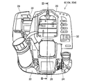
- FIG. 1 shows the appearance of a brush cutter 2 according to an embodiment of a portable work machine.
- the brush cutter 2 includes an operating rod 4, an engine 6 attached to the rear end of the operating rod 4, a gear head 8 attached to the front end of the operating rod 4, and a disc-shaped cutting blade attached to the gear head 8. 10, a safety cover 12 attached to the front end portion of the operation rod 4 so as to cover the cutting blade 10, and a handle 14 attached to an intermediate portion of the operation rod 4.
- the operation rod 4 has a hollow pipe shape and extends linearly.
- a drive shaft (not shown) is accommodated in the operation rod 4. Torque output from the engine 6 is transmitted to the gear head 8 via the drive shaft inside the operation rod 4 to rotate the cutting blade 10.
- the handle 14 includes a throttle lever (not shown) that performs a throttle operation of the engine 6, a stop switch (not shown) that stops the engine 6, and the like.
- the handle 14 further includes a warning LED 16 and a warning alarm 18.
- the warning LED 16 notifies the user of an abnormality in the oil level of the lubricating oil of the engine 6 by lighting.
- the warning alarm 18 notifies the user of an abnormality in the oil level of the lubricating oil of the engine 6 by sounding.
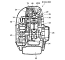
- Engine 6 is a so-called 4-stroke cycle engine. As shown in FIG. 2, the engine 6 includes an engine body 20, a fuel tank 22 that stores fuel such as gasoline, an oil pan 24 that stores lubricating oil, and a recoil starter 26 for starting the engine 6. . Further, the engine 6 includes an air cleaner 28 that filters intake air, a carburetor 30 that mixes fuel and intake air, a muffler 32 that cools and discharges high-temperature combustion gas discharged from the engine 6 to the atmosphere, and oil that will be described later A level sensor unit 92 (see FIG. 5) is provided.
- the fuel sent from the fuel tank 22 is vaporized by the carburetor 30 and then sent to the combustion chamber 34 of FIG. 3 through the air supply port.
- the fuel mixture sent into the combustion chamber 34 is ignited by the spark plug 36 and burns, and the combustion pressure of the combustion gas at that time is transmitted to the piston 38 to rotate the crankshaft 40.
- the combustion gas in the combustion chamber 34 is sent to the muffler 32 in FIG. 2 through the exhaust port, and is released into the atmosphere as exhaust gas.
- An intake valve 42 is disposed between the combustion chamber 34 and the intake port in FIG. 3, and an exhaust valve 44 is disposed between the combustion chamber 34 and the exhaust port.
- the opening and closing operations of the intake valve 42 and the exhaust valve 44 are controlled by a rocker arm 46 that operates in conjunction with the rotation of the crankshaft 40.
- the intake valve 42 and the exhaust valve 44 alternately perform one opening / closing operation while the crankshaft 40 rotates twice.
- crankshaft 40 One end (the left end in FIG. 3) of the crankshaft 40 is connected to the drive shaft inside the operation rod 4 in FIG. 1 via a clutch (not shown). The other end of the crankshaft 40 (the right end in FIG. 3) is connected to the recoil starter 26.
- a magneto circuit 48 is disposed in the vicinity of the crankshaft 40. The magneto circuit 48 generates power using the rotation of the crankshaft 40 and supplies power to the spark plug 36 and an oil level sensor unit 92 described later.
- the magnet circuit 48 includes a timing adjustment circuit (not shown) and can adjust the ignition timing of the spark plug 36. Further, the magnet circuit 48 includes a rotation speed detection circuit (not shown), and can detect the rotation speed of the crankshaft 40.
- the crankshaft 40 is provided with a valve drive gear 50 (see FIG. 4).
- the camshaft 52 (see FIG. 4), the cam follower, and the push rod 54 that follow the valve drive gear 50 prevent the rotational movement of the crankshaft 40 from being locked. This is converted into a periodic motion of the arm 46.
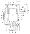
- FIG. 4 shows a lubricating oil circulation system of the engine 6.
- a suction part 56 for sucking lubricating oil is provided inside the oil pan 24.
- the suction part 56 has a tube 58 formed of an elastic material such as rubber, and a weight 60 with a suction port attached to the tip of the tube 58. Even when the engine 6 is used in a tilted state, the weight 60 moves in the direction of the action of gravity inside the oil pan 24, so that the suction port of the suction part 56 is always sunk below the liquid level of the lubricating oil. Include.
- the suction port of the suction part 56 communicates with the crank chamber 64 in which the crankshaft 40 is accommodated via the first oil feeding passage 62.
- a one-way valve 66 is provided in the first oil feeding passage 62.
- the opening communicating with the crank chamber 64 of the first oil feeding passage 62 is closed by the piston 38 while the piston 38 is lowered, and is opened when the piston 38 rises to near the top dead center.
- the inside of the crank chamber 64 tends to become negative pressure, and the lubricating oil is sucked up from the oil pan 24 and supplied to the crank chamber 64.
- the lubricating oil introduced into the crank chamber 64 from the first oil supply passage 62 is misted into oil mist, and lubricates the crank chamber 64.
- the lower part of the crank chamber 64 communicates with the oil pan 24 through a reed valve 75.
- a second oil feeding passage 72 is opened near the center of the oil pan 24, and the oil pan 24 communicates with the gear chamber 74 via the second oil feeding passage 72.
- the gear chamber 74 accommodates a valve drive gear 50, a cam gear 52, and the like.
- the gear chamber 74 communicates with the valve operating chamber 78 via the third oil feeding passage 76.
- the valve operating chamber 78 accommodates the rocker arm 46, the intake valve 42, the exhaust valve 44, and the like.
- the valve operating chamber 78 communicates with the crank chamber 64 via the fourth oil feeding passage 80.
- the opening communicating with the crank chamber 64 of the fourth oil feeding passage 80 is closed by the piston 38 while the piston 38 is lowered, and is opened when the piston 38 is raised to the vicinity of the top dead center.
- the crank chamber 64 tends to become positive pressure
- the reed valve 75 is opened, and the oil mist in the crank chamber 64 becomes the oil pan 24, the second It is sent to the gear chamber 74 through the oil feed passage 72.
- the oil mist sent to the gear chamber 74 is lubricated in the gear chamber 74 and then sent to the valve operating chamber 78 via the third oil feeding passage 76.
- the oil mist sent to the valve operating chamber 78 is lubricated in the valve operating chamber 78 and then sent to the crank chamber 64 via the fourth oil supply passage 80 when the piston 38 rises to near the top dead center. .
- a part of the oil mist sent from the crank chamber 64 to the oil pan 24 is liquefied and stored in the oil pan 24.
- the gear chamber 74 communicates with the crank chamber 64 via a return passage 77.
- the lubricating oil liquefied in the gear chamber 74 and accumulated in the gear chamber 74 is returned to the crank chamber 64 via the return passage 77 when the crank chamber 64 tends to have a negative pressure.
- a flow rate adjusting passage 79 is provided between the gear chamber 74 and the first oil feeding passage 62. The flow rate adjusting passage 79 adjusts the flow rate of the lubricating oil flowing through the first oil feeding passage 62 by allowing air to flow between the gear chamber 74 and the first oil feeding passage 62.
- the valve chamber 78 communicates with the air cleaner 28 via the breather passage 82.
- a one-way valve 84 is provided in the breather passage 82. Air containing oil mist and blow-by gas in the valve operating chamber 78 is sent to the air cleaner 28 via the breather passage 82.
- the oil mist is liquefied by the oil separator 86, and the lubricating oil is separated from the air containing blow-by gas.
- the blow-by gas is sent to the carburetor 30 together with air.
- the liquefied lubricating oil is sent to the crank chamber 64 via the fifth oil feeding passage 88.
- a one-way valve 90 is provided in the fifth oil supply passage 88.
- Oil level sensor 98 is attached to oil pan 24.
- the oil level sensor 98 is an electric resistance type level sensor.
- the oil level sensor 98 includes a ground electrode (not shown), an upper electrode 94 and a lower electrode 96.
- the oil level sensor 98 includes a state where the level of the lubricating oil is below the lower electrode 96, a state where the level of the lubricating oil is above the lower electrode 96 and below the upper electrode 94, and lubrication. A different signal is output for each of the states where the oil level is above the upper electrode 94.
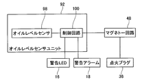
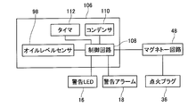
- FIG. 5 shows the configuration of the oil level sensor unit 92.
- the oil level sensor unit 92 includes an oil level sensor 98 and a control circuit 100. Based on the signal from the oil level sensor 98, the control circuit 100 determines whether or not the level of the lubricating oil stored in the oil pan 24 is within a predetermined range. The control circuit 100 transmits an instruction regarding ignition of the spark plug 36 to the magneto circuit 48. Further, the control circuit 100 controls lighting of the warning LED 16 and sounding of the warning alarm 18 as necessary.
- step S102 the control circuit 100 detects the level of the lubricating oil inside the oil pan 24 by the oil level sensor 98.
- step S104 the control circuit 100 determines whether or not the lubricant level detected by the oil level sensor 98 is within a predetermined range. If the level of the lubricating oil is within the predetermined range (in the case of YES), the oil level inspection process is terminated and the engine 6 is shifted to normal operation. When the level of the lubricating oil is not within the predetermined range (in the case of NO), the process proceeds to step S106.
- step S106 the control circuit 100 turns on the warning LED 16 and further sounds the warning alarm 18 to notify the user of the abnormality of the lubricating oil level.
- step S108 the magneto circuit 48 determines whether or not the engine 6 is idling. Whether the engine 6 is idling is determined, for example, by comparing the rotational speed of the engine 6 with a predetermined threshold value. When the engine 6 is idling (in the case of YES), the process returns to step S106 without limiting the rotational speed of the engine 6.
- step S110 the magneto circuit 48 suppresses the increase in the rotational speed of the engine 6. While the increase in the rotational speed of the engine 6 is suppressed, even if the user performs an operation to increase the rotational speed of the engine 6 with the throttle lever, the rotational speed of the engine 6 does not increase, and noise and vibration from the engine 6 Is for low rotation. Thus, since the operation of the engine 6 is different from the user's assumption, the user can be made aware of the abnormality.
- step S110 the process returns to step S106.
- the suppression of the increase in the rotational speed of the engine 6 in step S110 can be performed by various methods. For example, by limiting the number of times of ignition by the spark plug 36 to be less than that during normal operation, an increase in the rotational speed of the engine 6 can be suppressed. Specifically, an increase in the rotational speed of the engine 6 can be suppressed by making the spark plug 36 misfire. When the rotational speed of the engine 6 is thus suppressed, the power consumed by the spark plug 36 is suppressed, and the power generated by the magnet circuit 48 can be efficiently supplied to the warning LED 16 and the warning alarm 18.
- the increase in the rotational speed of the engine 6 in step S110 can be suppressed by advancing or retarding the timing of ignition by the spark plug 36 as compared to during normal operation.
- step S106 instead of notifying the user of the abnormality of the lubricant level using both the warning LED 16 and the warning alarm 18 as described above, the abnormality is notified to the user using only the warning LED 16. Alternatively, the user may be notified of the abnormality using only the warning alarm 18.
- the level of the lubricating oil is inspected when the engine 6 is started. Normally, when the engine 6 is started, the engine 6 is kept horizontal, and therefore the oil pan 24 is kept horizontal.
- the oil level sensor 98 can appropriately detect the level of the lubricating oil.
- the level of the lubricating oil is inspected only when the engine 6 is started, and the level of the lubricating oil is not inspected during the subsequent normal operation. Since there are restrictions due to fuel capacity, worker fatigue, etc., a single operation using the brush cutter 2 usually does not take several hours. For this reason, the lubricating oil does not rapidly decrease in one operation. In particular, when the engine 6 is a four-stroke cycle engine, unlike the case of the two-stroke cycle engine, the decrease in the lubricating oil in a single operation is negligible. If it is confirmed that the oil level is appropriate, it is not necessary to check the liquid level of the lubricating oil again until the end of the work. According to the brush cutter 2 of the present embodiment, the level of the lubricating oil is inspected with the minimum necessary frequency, and if the level of the lubricating oil is abnormal, the user can be surely notified.
- the brush cutter 2 of the present embodiment in addition to notifying the user of the presence of an abnormality using a warning device such as the warning LED 16 or the warning alarm 18 when the liquid level of the lubricating oil is not within the predetermined range, The presence of the abnormality is also notified to the user by suppressing the increase in the rotational speed of the engine 6.
- the user does not necessarily watch the warning LED 16, and the noise from the engine 6 makes it difficult to hear the warning alarm 18, so the warning LED 16 and the warning alarm 18 are not heard.
- the user may not be aware of anomaly notification due to.
- the noise and vibration from the engine 6 will be different from those assumed by the user of the brush cutter 2, so that the engine 6 is in a normal state. I feel that there is no. Further, since the warning LED 16 and the warning alarm 18 are notified together with the suppression of the increase in the rotational speed of the engine 6, the user operates the operation different from the assumption of the engine 6 due to the failure of the engine 6 itself. It can be known that this is due to an abnormality in the liquid level. According to the brush cutter 2 of the present embodiment, it is possible to reliably notify the user of an abnormality in the level of the lubricating oil.
- the power for turning on the warning LED 16 and sounding the warning alarm 18 can be supplied from the magneto circuit 48. There is no need to separately provide a dedicated power source for operating the warning LED 16 and the warning alarm 18.
- the brush cutter 102 according to the present embodiment has substantially the same configuration as the brush cutter 2 according to the first embodiment. Below, only the point which is different from the brush cutter 2 of Example 1 is demonstrated in detail.
- the engine 104 of the brush cutter 102 includes an oil level sensor unit 106.
- the oil level sensor unit 106 includes an oil level sensor 98, a control circuit 108, a capacitor 110, and a timer 112.
- the capacitor 110 is charged using the power of the magnet circuit 48 while the magnet circuit 48 is generating power.
- the capacitor 110 supplies power to the control circuit 108, the warning LED 16, and the warning alarm 18 after the magneto circuit 48 finishes generating the power.
- the timer 112 counts elapse of a predetermined time.
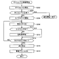
- step S202 the control circuit 108 detects the level of the lubricating oil inside the oil pan 24 by the oil level sensor 98.
- step S204 the control circuit 108 determines whether or not the lubricant level detected by the oil level sensor 98 is within a predetermined range. When the level of the lubricating oil is within the predetermined range (in the case of YES), the oil level inspection process is terminated and the engine 104 is shifted to normal operation. If the level of the lubricating oil is not within the predetermined range (in the case of NO), the process proceeds to step S206.
- step S206 the control circuit 100 starts counting by the timer 112.
- step S208 the control circuit 100 turns on the warning LED 16 to notify the user of an oil level abnormality.
- step S210 the magnet circuit 48 determines whether or not the engine 104 is idling. If the engine 104 is idling (in the case of YES), the process proceeds to step S214 without limiting the rotational speed of the engine 104.
- step S212 the magneto circuit 48 suppresses an increase in the rotational speed of the engine 104. Thereby, even when the user does not notice the lighting of the warning LED 16, the user can feel an abnormality through noise and vibration from the engine 104. After step S212, the process proceeds to step S214.
- step S216 the magneto circuit 48 prohibits ignition by the spark plug 36. As a result, the rotation of the engine 104 ends.
- step S218 the control circuit 108 sounds the warning alarm 18 to notify the user that the operation of the engine 104 has been stopped due to an abnormality in the lubricating oil level. After step S218, the oil level inspection process is terminated.
- the warning LED 16 when an abnormality in the liquid level of the lubricating oil is detected, first, the warning LED 16 is turned on and the number of revolutions of the engine 104 is suppressed. Thereafter, when a predetermined time elapses, the rotation of the engine 104 is stopped, and the user is notified by sounding the warning alarm 18. In a state where the increase in the rotational speed of the engine 104 is suppressed, the engine 104 is still rotating, and the noise from the engine 104 makes it difficult to hear the sound of the warning alarm 18. Therefore, in such a state, the warning LED 16 is turned on, but the warning alarm 18 is not sounded.
- the electric power generated by the magnet circuit 48 is charged in the capacitor 110, and after the ignition of the ignition plug 36 is prohibited, the electric power is supplied from the capacitor 110 to the warning alarm 18. With such a configuration, it is possible to reliably supply power to the warning alarm 18. Even in the case where the capacitor 110 is not provided, since a certain amount of time is required until the rotation of the crankshaft 40 is completely stopped after the ignition of the spark plug 36 is prohibited, the magneto circuit 48 is generated during that time. It is also possible to notify the abnormality by the warning alarm 18 using the power to be used.
- the brush cutter 202 according to the present embodiment has substantially the same configuration as the brush cutter 2 according to the first embodiment. Below, only the point which is different from the brush cutter 2 of Example 1 is demonstrated in detail.
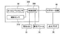
- the engine 204 of the brush cutter 202 includes an oil level sensor unit 206.
- the oil level sensor unit 206 includes an oil level sensor 98, a control circuit 208, and a tilt sensor 210.
- the tilt sensor 210 can detect the tilt angle of the oil pan 24 from the horizontal level, that is, the tilt angle of the engine 204 from the horizontal level.
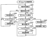
- step S302 the control circuit 208 detects the tilt angle of the oil pan 24 by the tilt sensor 210.
- step S304 it is determined whether or not the oil pan 24 is kept horizontal. Specifically, it is determined whether or not the inclination angle of the oil pan 24 is within a predetermined range. If the oil pan 24 is not kept horizontal (in the case of NO), the process proceeds to step S306.
- step S306 the control circuit 208 turns on the warning LED 16 and further sounds the warning alarm 18 to notify the user of an abnormal posture of the oil pan 24.
- step S308 the magnet circuit 48 determines whether or not the engine 204 is idling. If the engine 204 is idling (in the case of YES), the process returns to step S302 without limiting the number of revolutions of the engine 204.
- step S310 the magneto circuit 48 suppresses an increase in the rotational speed of the engine 204. Thereby, even when the user does not notice the lighting of the warning LED 16 or the ringing of the warning alarm 18, the user can be notified of the abnormality through the noise and vibration from the engine 204. After step S310, the process returns to step S302.
- step S304 If the oil pan 24 is kept horizontal in step S304 (in the case of YES), the process proceeds to step S312.
- step S ⁇ b> 312 the control circuit 208 detects the level of the lubricating oil inside the oil pan 24 by the oil level sensor 98.
- step S314 the control circuit 208 determines whether or not the level of the lubricating oil detected by the oil level sensor 98 is within a predetermined range. If the level of the lubricating oil is within the predetermined range (in the case of YES), the lighting of the warning LED 16 and the ringing of the warning alarm 18 are stopped in step S322, and the engine 204 is shifted to normal operation. If it is determined in step S314 that the level of the lubricating oil is not within the predetermined range (in the case of NO), the process proceeds to step S316.
- step S316 the control circuit 208 turns on the warning LED 16 and further sounds the warning alarm 18 to notify the user of the abnormality of the lubricating oil level.
- step S3108 the magnet circuit 48 determines whether or not the engine 204 is idling. If the engine 204 is idling (in the case of YES), the process returns to step S316 without limiting the number of revolutions of the engine 204.
- step S320 the number of revolutions of the engine 204 is suppressed in the magneto circuit 48. Thereby, even when the user does not notice the lighting of the warning LED 16 or the ringing of the warning alarm 18, the user can be notified of the abnormality through the noise and vibration from the engine 204.
- step S320 the process returns to step S316.
- the engine 204 is kept horizontal when the engine 204 is started, and only when the level of the lubricating oil in the oil pan 24 is within a predetermined range. In other cases, the engine 204 is switched to the normal operation, and in addition to the notification using the warning LED 16 and the warning alarm 18, the rotational speed of the engine 204 is suppressed. Accordingly, even when the engine 204 is not kept horizontal when the engine 204 is started and therefore the oil level sensor 98 cannot properly detect the liquid level of the lubricating oil, the user can be notified of the abnormality. In this case, if the engine 204 is returned to the horizontal state and it is determined that the level of the lubricating oil is normal in that state, the engine 204 can be shifted to normal operation.
- step S310 instead of notifying the user of the abnormality using both the warning LED 16 and the warning alarm 18 as described above, only the warning LED 16 is used to notify the user of the abnormality. Or the user may be notified of the abnormality using only the warning alarm 18.
- the brush cutter 102 according to the second embodiment may be combined with the inclination sensor 210 according to the third embodiment so that the oil pan 24 is kept horizontal when the level of the lubricating oil is inspected.
Landscapes
- Engineering & Computer Science (AREA)
- Mechanical Engineering (AREA)
- General Engineering & Computer Science (AREA)
- Lubrication Details And Ventilation Of Internal Combustion Engines (AREA)
- Harvester Elements (AREA)
- Output Control And Ontrol Of Special Type Engine (AREA)
Abstract
L'invention concerne une technique se rapportant à une machine de travail portable ayant monté sur celle-ci un moteur à combustion interne comportant un réservoir d'huile de graissage, la technique étant configurée de sorte que, quand il y a une anomalie au niveau de la quantité d'huile de graissage retenue dans le réservoir d'huile de graissage, la technique peut signaler l'anomalie avec précision à l'utilisateur. La machine de travail portable de l'invention comporte : un capteur de niveau d'huile permettant de détecter le niveau de l'huile de graissage retenue dans le réservoir d'huile de graissage ; un dispositif de réglage de vitesse de rotation en mesure de régler la vitesse de rotation du moteur à combustion interne ; et un premier dispositif d'avertissement permettant de signaler à l'utilisateur une anomalie se rapportant au niveau de l'huile de graissage. Le dispositif de travail portable inspecte automatiquement le niveau de l'huile de graissage, qui est retenue dans le réservoir d'huile de graissage, au cours de la période allant du démarrage du moteur à combustion interne jusqu'au démarrage du travail de l'utilisateur. Au cours de l'inspection du niveau de l'huile de graissage, si la valeur détectée par le capteur de niveau d'huile ne se trouve pas dans les limites d'une plage prédéterminée, le dispositif de travail portable signale l'anomalie à l'utilisateur au moyen du premier dispositif d'avertissement et empêche une augmentation de la vitesse de rotation du moteur à combustion interne au moyen du dispositif de réglage de vitesse de rotation.
Applications Claiming Priority (2)
| Application Number | Priority Date | Filing Date | Title |
|---|---|---|---|
| JP2011-065743 | 2011-03-24 | ||
| JP2011065743A JP2012202257A (ja) | 2011-03-24 | 2011-03-24 | 潤滑油槽を備える内燃機関を搭載した携帯型作業機 |
Publications (1)
| Publication Number | Publication Date |
|---|---|
| WO2012127747A1 true WO2012127747A1 (fr) | 2012-09-27 |
Family
ID=46878935
Family Applications (1)
| Application Number | Title | Priority Date | Filing Date |
|---|---|---|---|
| PCT/JP2011/079315 Ceased WO2012127747A1 (fr) | 2011-03-24 | 2011-12-19 | Machine de travail portable ayant monté sur celle-ci un moteur à combustion interne comportant un réservoir d'huile de graissage |
Country Status (2)
| Country | Link |
|---|---|
| JP (1) | JP2012202257A (fr) |
| WO (1) | WO2012127747A1 (fr) |
Families Citing this family (1)
| Publication number | Priority date | Publication date | Assignee | Title |
|---|---|---|---|---|
| JP6868495B2 (ja) * | 2017-07-21 | 2021-05-12 | 株式会社マキタ | 手持式作業機 |
Citations (5)
| Publication number | Priority date | Publication date | Assignee | Title |
|---|---|---|---|---|
| JPS6030428A (ja) * | 1983-07-28 | 1985-02-16 | Sanshin Ind Co Ltd | エンジンの異常警告装置 |
| JPS61123815U (fr) * | 1985-01-23 | 1986-08-04 | ||
| JPH09209737A (ja) * | 1996-01-31 | 1997-08-12 | Mitsubishi Heavy Ind Ltd | オイルレベルセンサ |
| JP2001254614A (ja) * | 2000-03-09 | 2001-09-21 | Hino Motors Ltd | 油圧警報装置 |
| JP2007535635A (ja) * | 2004-04-30 | 2007-12-06 | ワツカー コンストラクション イクイップメント アクチェンゲゼルシャフト | 内燃機関のためのオイルレベル監視装置 |
-
2011
- 2011-03-24 JP JP2011065743A patent/JP2012202257A/ja not_active Withdrawn
- 2011-12-19 WO PCT/JP2011/079315 patent/WO2012127747A1/fr not_active Ceased
Patent Citations (5)
| Publication number | Priority date | Publication date | Assignee | Title |
|---|---|---|---|---|
| JPS6030428A (ja) * | 1983-07-28 | 1985-02-16 | Sanshin Ind Co Ltd | エンジンの異常警告装置 |
| JPS61123815U (fr) * | 1985-01-23 | 1986-08-04 | ||
| JPH09209737A (ja) * | 1996-01-31 | 1997-08-12 | Mitsubishi Heavy Ind Ltd | オイルレベルセンサ |
| JP2001254614A (ja) * | 2000-03-09 | 2001-09-21 | Hino Motors Ltd | 油圧警報装置 |
| JP2007535635A (ja) * | 2004-04-30 | 2007-12-06 | ワツカー コンストラクション イクイップメント アクチェンゲゼルシャフト | 内燃機関のためのオイルレベル監視装置 |
Also Published As
| Publication number | Publication date |
|---|---|
| JP2012202257A (ja) | 2012-10-22 |
Similar Documents
| Publication | Publication Date | Title |
|---|---|---|
| JP5264198B2 (ja) | 内燃エンジンの作動方法 | |
| JP5417249B2 (ja) | 汎用エンジンの転倒検出装置 | |
| US7325526B2 (en) | Four-stroke engine system | |
| JPS6040716A (ja) | エンジンの燃焼制御装置 | |
| US7367328B2 (en) | Four-cycle engine and motorcycle comprising four-cycle engine | |
| US7325528B2 (en) | Method of operating a single cylinder two-stroke engine | |
| US6655343B2 (en) | Engine control system for an outboard motor | |
| US8347858B2 (en) | Load condition detection apparatus for general-purpose engine | |
| US10180091B2 (en) | Breather apparatus for engine | |
| WO2012127747A1 (fr) | Machine de travail portable ayant monté sur celle-ci un moteur à combustion interne comportant un réservoir d'huile de graissage | |
| US7509940B2 (en) | Marine engine | |
| JP2007239460A (ja) | 汎用エンジンのオイルレベル低下判断装置 | |
| JP4658815B2 (ja) | 単気筒2サイクルエンジンの作動方法 | |
| US7826955B2 (en) | General-purpose internal combustion engine | |
| JP5369070B2 (ja) | 汎用エンジンの燃料切れ判定装置 | |
| JP2017089415A (ja) | 燃料タンク内蔵型の船外機 | |
| JP2007023839A (ja) | 汎用内燃機関 | |
| JP2005220869A (ja) | 汎用エンジンのオイルセンサ | |
| JP2016098645A (ja) | 内燃機関 | |
| JP2015094216A (ja) | エンジンの燃料供給装置及び運転方法 | |
| JP7514816B2 (ja) | エンジンのブリーザ装置 | |
| JP2008267173A (ja) | 車両並びにその制御装置および制御方法 | |
| JP5357120B2 (ja) | 汎用エンジンの燃料切れ判定装置 | |
| JP2565251Y2 (ja) | 2サイクルエンジンのオイル給送装置 | |
| JP2016118156A (ja) | エンジン作業機 |
Legal Events
| Date | Code | Title | Description |
|---|---|---|---|
| 121 | Ep: the epo has been informed by wipo that ep was designated in this application |
Ref document number: 11861472 Country of ref document: EP Kind code of ref document: A1 |
|
| NENP | Non-entry into the national phase |
Ref country code: DE |
|
| 122 | Ep: pct application non-entry in european phase |
Ref document number: 11861472 Country of ref document: EP Kind code of ref document: A1 |