WO2012127767A1 - Dispositif de sertissage de borne - Google Patents
Dispositif de sertissage de borne Download PDFInfo
- Publication number
- WO2012127767A1 WO2012127767A1 PCT/JP2012/000600 JP2012000600W WO2012127767A1 WO 2012127767 A1 WO2012127767 A1 WO 2012127767A1 JP 2012000600 W JP2012000600 W JP 2012000600W WO 2012127767 A1 WO2012127767 A1 WO 2012127767A1
- Authority
- WO
- WIPO (PCT)
- Prior art keywords
- terminal
- inspection
- electric wire
- terminal crimping
- crimping apparatus
- Prior art date
- Legal status (The legal status is an assumption and is not a legal conclusion. Google has not performed a legal analysis and makes no representation as to the accuracy of the status listed.)
- Ceased
Links
Images







Classifications
-
- H—ELECTRICITY
- H01—ELECTRIC ELEMENTS
- H01R—ELECTRICALLY-CONDUCTIVE CONNECTIONS; STRUCTURAL ASSOCIATIONS OF A PLURALITY OF MUTUALLY-INSULATED ELECTRICAL CONNECTING ELEMENTS; COUPLING DEVICES; CURRENT COLLECTORS
- H01R43/00—Apparatus or processes specially adapted for manufacturing, assembling, maintaining, or repairing of line connectors or current collectors or for joining electric conductors
- H01R43/04—Apparatus or processes specially adapted for manufacturing, assembling, maintaining, or repairing of line connectors or current collectors or for joining electric conductors for forming connections by deformation, e.g. crimping tool
- H01R43/048—Crimping apparatus or processes
- H01R43/05—Crimping apparatus or processes with wire-insulation stripping
-
- H—ELECTRICITY
- H01—ELECTRIC ELEMENTS
- H01R—ELECTRICALLY-CONDUCTIVE CONNECTIONS; STRUCTURAL ASSOCIATIONS OF A PLURALITY OF MUTUALLY-INSULATED ELECTRICAL CONNECTING ELEMENTS; COUPLING DEVICES; CURRENT COLLECTORS
- H01R43/00—Apparatus or processes specially adapted for manufacturing, assembling, maintaining, or repairing of line connectors or current collectors or for joining electric conductors
- H01R43/04—Apparatus or processes specially adapted for manufacturing, assembling, maintaining, or repairing of line connectors or current collectors or for joining electric conductors for forming connections by deformation, e.g. crimping tool
- H01R43/048—Crimping apparatus or processes
- H01R43/0486—Crimping apparatus or processes with force measuring means
Definitions
- the present invention relates to a terminal crimping apparatus that crimps a terminal that exposes a core wire of an electric wire and conducts to the core wire to the end portion of the electric wire by removing a covering material at the end portion of the electric wire.
- terminals crimped by this type of terminal crimping device must not be pulled out below a specified force, so it is necessary to inspect whether they are crimped normally.
- the automatic evaluation apparatus for a terminal-attached electric wire disclosed in Patent Document 1 receives a test electric wire having one end crimped, and a crimp height measuring unit that measures the crimp height of the terminal fitting of the received test electric wire, the first automatic Inspection unit including a conveyance unit, a contact resistance measurement unit that measures the contact resistance value of the terminal fitting, a second automatic conveyance unit, and a fixing force measurement unit that measures the tensile strength of the terminal fitting, and an inspection result of this inspection unit And a data processing unit for storing and outputting for each test electric wire.
- the crimping part illumination light with a predetermined hue is applied to the crimping part of the crimping terminal, and the background body of the hue different from the crimping part illumination light is applied to the background body of the crimping part.
- the conventional terminal crimping device performs inspection at the time of initial setting and sampling inspection, and does not automatically inspect every number or fixed number during the production of product electric wires. Even if it is initially set to an appropriate value, defective products that occur cannot be found.
- the present invention has been made in view of such points, and the object of the present invention is to automatically inspect the total number of terminals in a crimped state or a certain number automatically with a simple configuration during manufacture of a product electric wire. This is to prevent the occurrence of defective products.
- a tensile inspection of the crimp terminal is performed immediately after crimping.
- the terminal crimping device that crimps the terminal that exposes the core wire of the electric wire and conducts to the core wire to the end of the electric wire
- the terminal crimping device A gripping device for gripping and moving the wire;
- the crimped terminal is inspected from the change that occurs in the driving device by pulling the electric wire by a predetermined distance with the holding device while holding the terminal after the crimping with a holding member. An inspection device.
- the terminal is held by the holding member, the tensile inspection is performed, and the change that occurs in the driving device that drives the gripping device Since the terminal is inspected for the crimping state, it can be inspected automatically instead of manually.
- the change that occurs in the drive device is a change in the torque of the drive device.
- the drive device is a servo motor
- the change that occurs in the drive device is a change in the position sensor of the servo motor.
- the servo motor rotates at a constant speed at first, and when the electric wire is fully extended, the one with a good crimped state stops after the speed gradually decreases. In the case of a poorly crimped state, the electric wire starts moving and the speed increases again.
- the change in the rotation of the servo motor is detected by the position sensor such as an encoder, whereby the crimped state is easily inspected.
- the servo motor here is a general term for motors that can automatically control position, orientation, orientation, and the like.
- a change occurring in the driving device is measured by a displacement of the holding member.
- a change occurring in the driving device is detected by a change in load applied to the holding member.
- the load of the holding member increases little by little, and the constant load is maintained in the good crimped state, but the electric wire starts moving in the poorly crimped state.
- the load decreases. For this reason, by detecting the displacement of the holding member, the crimped state is easily inspected.
- the holding member is a press member that crimps the terminal.
- the press member is opened by a predetermined amount after the terminal is crimped, and the press member is placed around a wire barrel that is a crimping portion between the core wire and the terminal.
- the terminal is held by being hooked on the protruding bell mouth portion.
- the electric wire is inspected with the press member slightly opened and held to the extent that it is caught by the bell mouth portion around the wire barrel formed by the crimping immediately after the crimping, so it is necessary to move the electric wire. There is no need to provide a separate holding member. For this reason, a simple configuration is achieved, and the crimped state is easily inspected.
- the holding member is configured to be hooked on an insulation barrel that is a crimping portion between the terminal and the covering material to hold the terminal.
- the holding member is configured to hold the terminal on the tip side of the crimping portion of the terminal.
- the predetermined distance is set to a length that prevents the terminal from coming out of the electric wire.
- a plurality of inspection items can be stored, and an inspection can be performed by any combination of at least one of the plurality of inspection items.
- the tenth or eleventh invention As parameters corresponding to each of the inspection items, the presence / absence of execution, the interval of the number of crimps to be inspected, the inspection type, the tensile force, and the tensile distance can be arbitrarily changed.
- the electric wire is pulled by a predetermined load with a predetermined load with a holding device while the terminal after crimping is held by the holding member, and the holding device is driven. Since the crimping state of the terminal is inspected from the change that occurs in the driving device, it is possible to prevent the occurrence of defective products by automatically inspecting the total number of the terminal crimping state or every fixed number with a simple configuration. it can.
- the press member of the terminal crimping apparatus of this embodiment shows a mode that a terminal is crimped, (a) is a front view, (b) is an Ib part enlarged view of (a), (c) is (b). It is an Ic-Ic line sectional view. It is a top view which shows arrangement
- FIG. 8 is a view corresponding to FIG. 7 when there is a defective crimping state.
- maintained with the holding bracket concerning the modification 1 is shown, (a) is a front view, (b) is a side view.
- FIG. 7 is a view corresponding to FIG. 6 according to Modification 1.
- FIG. 10 is a diagram corresponding to FIG. 9 according to Modification 2. It is a front view which shows the test
- FIG. 7 is a view corresponding to FIG. 6 according to Modification 4.
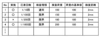
- 10 is a table showing parameters corresponding to inspection items according to Modification 4.
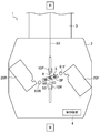
- FIG. 2 shows a simplified layout of the terminal crimping apparatus 1 according to the embodiment of the present invention.
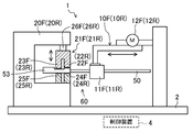
- FIG. 3 shows a front part (rear part) of the terminal crimping apparatus 1.
- the terminal crimping apparatus 1 includes a base 2 in which members such as steel plates are assembled, and various devices that continuously perform terminal processing at both ends of the electric wire 50 having a predetermined length are arranged on the base 2.
- the winding roll (not shown) side around which the electric wire 50 is wound is a front stage, and the tip side of the electric wire 50 is a rear stage.
- the electric wire 50 consists of what covered the core wire 51 comprised, for example with conductors, such as a copper wire, with the coating
- the terminal crimping apparatus 1 has an electric wire supply mechanism 3, and the electric wire supply mechanism 3 includes a wire drawing machine and a length measuring unit (not shown).
- the winding wrinkle at the time of winding with a winding roll with a wire drawing machine is correct
- the terminal crimping device 1 includes a control device 4 configured by a processor including a CPU, a memory, and the like.
- the control device 4 performs various control targets of the terminal crimping device 1 based on signals from various sensors of the terminal crimping device 1. It controls the operation of the equipment.
- the control device 4 may be singular or plural, and the installation location is not limited.
- the cutter unit 5 is arranged on the base 2.
- the cutter unit 5 is used for cutting the electric wire 50 and stripping the covering material 52 of the end portions 50F and 50R of the electric wire 50.
- the cutter unit 5 is arranged in the vicinity of the nozzle 6 from which the electric wire 50 is drawn out, and the electric wire cutting blade 5C arranged perpendicular to the supply direction of the electric wire 50 for cutting the electric wire 50, and both sides of the electric wire cutting blade 5C.
- a pair of gripping devices 10F and 10R for gripping and moving the electric wire 50 are provided on the base 2, a pair of gripping devices 10F and 10R for gripping and moving the electric wire 50.
- the gripping devices 10F and 10R include hands 11F and 11R that grip the electric wire 50, and the hands 11F and 11R are configured to be driven by servo motors 12F and 12R as driving devices.
- the motor driver 13 is configured to control the servo motors 12 ⁇ / b> F and 12 ⁇ / b> R in response to an instruction from the control device 4, and the control device 4 is in a state of the servo motors 12 ⁇ / b> F and 12 ⁇ / b> R from the motor driver 13. Is obtained from information on current, an encoder as a position sensor, and the like.
- a pair of crimping machines 20F and 20R are provided on the base 2.
- the crimping machines 20F and 20R include press members 21F and 21R, respectively, and the press members 21F and 21R are respectively provided with a pair of insulation side crimpers 22F and 22R and wire side crimpers. 23F, 23R, and a pair of insulation side anvils 24F, 24R and wire side anvils 25F, 25R.
- the pair of insulation side crimpers 22F and 22R and the wire side crimpers 23F and 23R are configured to be moved up and down by pressure cylinders 26F and 26R, respectively.
- the end portions 50F, 50R of the electric wire 50 are respectively connected to the respective terminals 53.
- the insulation barrel 54 is caulked to the wire covering material 52
- the wire barrel 55 is caulked to the core wire 51 by being sent to the upper part and lowering the pressure cylinders 26 ⁇ / b> F and 26 ⁇ / b> R.
- a raised bell mouth portion 56 is formed around the wire barrel 55.
- the crimping force at this time is detected by a load sensor such as a load cell (not shown) provided in the crimping machines 20F and 20R.
- a connecting portion 57 at the tip of the terminal 53 is formed to be larger than the outer diameter of the wire barrel 55 or the insulation barrel 54 and is connected to an electric device.
- the crimping machines 20F and 20R include an inspection device 60 that inspects the crimping state of the terminal 53.
- the inspection device 60 inspects the crimped state from the changes that occur in the servo motors 12F, 12R by pulling the electric wire 50 by a predetermined load with a predetermined load with the gripping devices 10F, 10R while holding the terminal 53 after crimping with a holding member. Is configured to do.
- the press members 21F and 21R serve as holding members.
- the change that occurs in the servo motors 12F and 12R is a change in the torque (tensile force) of the servo motors 12F and 12R, and this change can also be detected as a change in the rotation of the servo motor.
- the camera 30 is provided in the inspection areas 61F and 61R (shown in FIG. 2) as an inspection apparatus.
- the image processing device 31 compares the image captured by the camera 30 and the image stored in the normal crimped state in advance, and when there is an unacceptable difference between them, an abnormality is found in the control device 4. You may make it send the signal to that effect.
- the control device 4 is programmed in advance with the wire processing, and the control device 4 controls the terminal crimping device 1 as follows.
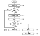
- a crimping process of the terminal 53 of the electric wire 50 is performed in step S10. Specifically, first, the electric wire 50 corresponding to the cutting length is fed out from the electric wire cutting blade 5C by the length measuring unit of the electric wire supply mechanism 3, and is gripped by the gripping device 10R. In this state, the electric wire 50 is cut by the electric wire cutting blade C. Thereby, the electric wire 50 by which the terminal 53 was crimped
- the covering material 52 of the end portions 50F and 50R of the electric wire 50 is removed by the stripping blades 5F and 5R while the pair of electric wires 50 are held by the holding devices 10F and 10R. Line 51 is exposed.
- a terminal 53 that is electrically connected to the core wire 51 is crimped to the end portions 50F and 50R of the electric wire 50.
- both end portions 50F and 50R are respectively attached to the press members 21F and 21R of the crimping machines 20F and 20R, and the pressure cylinders 26F and 26R are lowered as described above.
- the insulation barrel 54 and the wire barrel 55 are pressure-bonded to form the bell mouth portion 56.
- step S101 it is determined whether or not a tensile inspection is performed by holding the crimped terminal 53 with a holding member.
- This determination may be set so that inspections are performed at intervals (for example, after a certain number of times of crimping is performed) as in Modification 4 described later, or set to be performed every time crimping is performed. Thus, it is determined whether the number of times of crimping is the set number.
- the process jumps to step S14.
- the process proceeds to step S11.
- step S11 as shown in FIG. 1, the pressing members 21F and 21R serving as holding members are pressed by a predetermined amount after the terminal 53 is pressed (the bell mouth portion 56 is not applied with a load in a direction to be sandwiched between the wire barrels 55).
- the press members 21F and 21R are retracted only by a degree not exceeding), and the terminals 53 are held by being hooked on the bell mouth portion 56.
- step S12 inspection is started. Specifically, the servo motors 12F and 12R that drive the gripping devices 10F and 10R are driven, and the electric wires 50 are pulled in the directions of the arrows in FIG. 1A to monitor changes that occur in the servo motors 12F and 12R.
- Various monitoring methods can be considered.
- changes in torque and speed of the servo motors 12F and 12R are detected. Only one of the torque and speed may be detected.
- the control device 4 detects changes in the current generated in the motor driver 13 and the pulse of the encoder. Thereby, in step S13, it is determined whether it is a non-defective product according to the crimping state of the terminal 53.
- Hours 1 to 5 are constant speed movements at the maximum speed.
- the motor torque is ideally 0, in the actual terminal crimping apparatus 1, a loss such as friction occurs, so that a constant torque is required as shown in FIG.
- control device 4 determines that both of the crimped states of the terminals 53 are good, and proceeds to step S14 to perform normal processing and later as a good product. Flowed into the process
- the control device 4 identifies the defective electric wire 50 from the detection result of the servo motors 12F and 12R that have any abnormality. That is, the control device 4 is a defective product when there is a place where the speed does not become zero within a predetermined time or continues to move, or the speed at which the speed starts to decrease increases again and the negative acceleration turns to positive. Judge. Further, the control device 4 determines that the product is defective when the torque that has started to increase to some extent decreases again.
- step S15 the process proceeds to step S15 and an alarm is issued.
- the terminal 53 is set to proceed to step S15 where the terminal 53 does not come out of the electric wire 50.
- step S16 the defective product is moved to the defective storage area, and the operation is started after returning to the start.
- step S15 by adjusting the timing of proceeding to step S15, even if the crimping state is poor and the terminal 53 is loosened by the tensile inspection, it does not completely separate from the electric wire 50, so there is no need to search for the disconnected terminal 53, Since the defective electric wire 50 can be immediately moved to the next crimping operation of the electric wire 50 just by placing it in the defective product storage place, the work efficiency is good. In addition, what is necessary is just to stop an alarm suitably after an operator confirms the defective article of a defective storage place.
- step S12 the above-described tensile inspection may be performed, but the image processing shown in FIG. 5 may be added as an inspection item.
- the electric wire 50 after crimping is moved to the inspection areas 61F and 61R and photographed by the camera 30, and an image captured by the camera 30 and a normal crimped image stored in advance are image processing apparatuses.
- a signal indicating that an abnormality has been found is sent to the control device 4.
- the process may proceed to step S15.
- the electric wire 50 is gripped by pulling a predetermined distance with a predetermined load by the gripping devices 10F and 10R in a state where the terminal 53 after the crimping is held by the press members 21F and 21R. Since the crimping state of the terminal 53 is inspected from the changes that occur in the servo motors 12F, 12R that drive the devices 10F, 10R, the entire terminal crimping state is automatically inspected with a simple configuration, not manually. Occurrence of malfunctions can be prevented.
- FIG. 9 shows a first modification of the embodiment of the present invention.
- the configuration of the holding member is different from that of the above embodiment.
- the same parts as those in FIGS. 1 to 8 are denoted by the same reference numerals, and detailed description thereof is omitted.
- the holding member includes holding brackets 62F and 62R arranged in the inspection areas 61F and 61R.
- the holding brackets 62F and 62R have slits 63F and 63R having a width slightly larger than the outer diameter of the covering material 52 of the electric wire 50 and smaller than the outer diameter of the insulation barrel 54 of the terminal 53.
- step S11 is newly replaced with step S21. That is, each electric wire 50 is moved by the hands 11F and 11R, the electric wire 50 portion in front of the insulation barrel 54 is inserted from above the slits 63F and 63R, and the terminal 53 is held by the holding brackets 62F and 62R. Has been.
- the number of steps of moving each electric wire to the inspection areas 61F and 61R is increased as compared with the above embodiment.
- the outer diameter of the portion to be held is larger than that in the case of being held by the bell mouth portion 56 and the holding is easy. It is also advantageous when it is desired to avoid damage to the press members 21F and 21R as much as possible. Even in this case, a tensile inspection may be performed as in the above embodiment.
- FIG. 11 shows a second modification of the embodiment of the present invention.
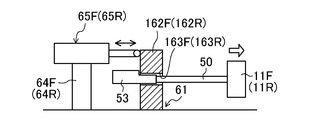
- the structure of the holding member is different from the above-described embodiment. That is, in the present modification, the holding member includes the upper holding members 162F and 162R and the lower holding members 164F and 164R arranged in the inspection regions 61F and 61R, and operates so that both the holding members approach and separate from each other. .
- the configuration of the holding member is different from that of the first modification.
- the electric wires 50 are moved to the spaces 163F and 163R between the upper holding members 162F and 162R and the lower holding members 164F and 164R by the hands 11F and 11R, and the connection of the terminal 53 on the tip side with respect to the wire barrel 55 is performed.
- the upper holding members 162F and 162R and the lower holding members 164F and 164R operate so as to be close to each other by using a cylinder (not shown) as a drive source, grasping the tip side of the terminal crimping portion,
- the connection portion 57 is fixed with a load that does not deform.
- the number of steps of moving each electric wire 50 to the inspection regions 61F and 61R is increased as compared with the above embodiment, but the outer diameter of the connection portion 57 is larger than the case where the electric wire 50 is held by the bell mouth portion 56 and the holding is held. There is a merit that it is easy as well. Even in this case, a tensile inspection may be performed as in the above embodiment.
- FIG. 12 shows a third modification of the embodiment of the present invention, which is different from the above-described embodiment in that a change occurring in the servo motors 12F and 12R is detected by a change in the load applied to the holding member. This is effective when the holding member is configured as in 1 or Modification 2.
- contact-type displacement gauges 65F and 65R fixed to the displacement gauge fixing tools 64F and 64R are brought into contact with the holding brackets 162F and 162R.
- contact displacement meters 65F and 65R are used, but non-contact displacement meters such as laser displacement meters 165F and 165R may be used as shown in FIG.
- load cells 265F and 265R may be provided at the base end portions of the holding brackets 162F and 162R to detect a load due to a bending moment applied to the base end portions.
- the wire 50 is slack in the time 0 to 5 shown in FIG. 7 in a normal crimped state, so that the displacement and load are detected almost at zero.
- a displacement and a load also change with a change of motor torque. That is, when the electric wire 50 is pulled by the gripping devices 10F and 10R, the displacement and load of the holding brackets 162F and 162R increase little by little, and after that, in a good crimped state, a constant displacement or load is maintained. In a bad state, the electric wire 50 starts to move, and the displacement or load change returns to almost zero. For this reason, by detecting the displacement or load change of the holding member, the crimped state is easily inspected.
- the inspection in the third modification may be additionally performed in addition to the inspection method in the first or second modification.
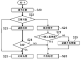
- -Modification 4- 15 and 16 show a fourth modification of the embodiment of the present invention, which is different from the above-described embodiment in that a plurality of inspection items are stored and the inspection is performed by arbitrarily combining them. .
- step S20 the crimping process of the terminal 53 of the electric wire 50 is performed in the same manner as in the above embodiment.
- step S22 the presence / absence and type of inspection are determined based on the number of times of crimping.
- at least four or more inspection items are stored.
- Inspection item 1 is an inspection performed once every 10 times of crimping
- inspection item 2 is performed once every 100 times.
- the inspection item 3 is performed once every 200 times, but is not performed because execution is not selected here.
- the inspection item 4 is a destructive test that is performed once every 1000 times, and the inspection load exceeds a reference value of 180, which is a limit value of the load that is supposed to be inherent (required tensile strength of the terminal 53 to be set).
- this step S22 it is determined from the current number of times of crimping whether or not it is the number of times of crimping specified in the inspection item, the inspection frequency, and the selected inspection item.
- the determination is performed every 10 times for inspection item 1, every 100 times for inspection item 2, and every 1000 times for inspection item 4, and when the other number of times of crimping is not a multiple of 10, the inspection is not performed.
- the process jumps to step S25 and normal processing is performed.
- inspection item 2 is performed.
- inspection item 4 is preferentially performed.
- step S23 When the number of times of crimping is a multiple of 10 and not a multiple of 100, the process proceeds to step S23 and a normal inspection is performed in the same manner as in the above embodiment.
- the inspection load is 100 and the inspection distance is 2 mm.
- step S24, step S25, or step S28 is performed as in the above embodiment. In this case, since the inspection load is smaller than the reference value of 180, the terminal 53 is not damaged and can be used as a product.
- step S26 when it is not a multiple of 1000, inspection item 2 is performed.
- the limit inspection is performed with an inspection load 150 in which the inspection load is higher than the normal inspection (load 100).
- a load is gradually applied up to 150. For example, when the terminal 53 is destroyed at 140 before the load reaches 150 and the load decreases, 140 immediately before the load decreases is stored as a peak value. Since the magnitude of the inspection load is set as high as 150, the terminal 53 may be broken.
- inspection item 4 is performed in preference to inspection item 2.
- the inspection load is 200 and exceeds the reference value of 180, it can be predicted that the terminal 53 is completely destroyed. Even in the inspection item 4, if the terminal 53 is broken before reaching the inspection load 200, the load decreases at that time, and the load immediately before that is stored as a peak value. For example, when the inspection load increases to 190 and then the terminal 53 is destroyed and the load decreases, the peak value is stored as 190.
- step S27 it is determined whether the stored load peak value is 180 or more, which is the reference value. If it is 180 or more, it means that the terminal 53 has the necessary tensile strength and it is determined that it has been caulked without any problem, and the process proceeds to step S28. Since the terminal 53 is destroyed at a high rate in the limit inspection, it cannot be used as a product, and defect processing is performed as in the above embodiment.
- step S29 If abnormality of the terminal crimping apparatus 1 is assumed, it progresses to step S29 and an apparatus failure alarm is performed. Thereby, the terminal crimping apparatus 1 is corrected. And it progresses to step S28 and a defect process is performed.
- inspection item 3 may be executed with priority over inspection items 1 and 2 every 200 times in the determination of step S22.
- the setting of the inspection item 1 may be changed so that all inspections are performed, and parameters such as the inspection type, tensile force, and tensile distance can be arbitrarily set, including the interval of the number of crimps corresponding to each inspection item.
- the setting can be changed.
- the electric wire 50 used as a product is loaded more than necessary.
- the present invention is useful for a terminal crimping device that crimps a terminal that exposes a core wire of a wire and conducts to the core wire to the end portion of the wire by removing the covering material at the end of the wire. It is.
- Terminal crimping device 4 Control device 10F, 10R Gripping device 12F, 12R Servo motor (drive device) 21F, 21R Press member (holding member) 50 Electric wire 50F, 50R End portion 51 Core wire 52 Coating material 53 Terminal 54 Insulation barrel 55 Wire barrel 56 Bell mouth portion 57 Connection portion 60 Inspection device 62F, 62R Holding bracket 64F, 64R Displacement meter fixture 65F, 65R Contact type Displacement meter 162F, 162R Bracket for holding 165F, 165R Laser displacement meter 265F, 265R Load cell
Landscapes
- Engineering & Computer Science (AREA)
- Manufacturing & Machinery (AREA)
- Manufacturing Of Electrical Connectors (AREA)
Abstract
Dans la présente invention, un dispositif de saisie qui agrippe et déplace le fil électrique (50) et un dispositif d'entraînement qui entraîne le dispositif de saisie sont prévus, et par retrait d'un matériau de recouvrement (52) d'une partie de bord du fil électrique (50), un fil d'âme (51) d'un fil électrique (50) est exposé de façon à sertir une borne (53) sur la partie de bord du fil électrique (50) et à rendre le terminal (53) conducteur vers le fil d'âme (51). Dans un dispositif d'inspection, le fil électrique (50) est tiré par le dispositif de saisie avec une charge prédéterminée pour une distance prédéterminée sous la condition où la borne sertie (53) est maintenue par des éléments de pression (21F, 21R) (éléments de retenue), de façon à inspecter la condition de sertissage de la borne (53) sur la base du changement qui survient dans le dispositif d'entraînement. De cette manière, en présentant une configuration simple, la condition de sertissage de la borne est automatiquement et totalement inspectée, de telle sorte que l'occurrence de défauts est empêchée.
Applications Claiming Priority (2)
| Application Number | Priority Date | Filing Date | Title |
|---|---|---|---|
| JP2011-066595 | 2011-03-24 | ||
| JP2011066595A JP2012204102A (ja) | 2011-03-24 | 2011-03-24 | 端子圧着装置 |
Publications (1)
| Publication Number | Publication Date |
|---|---|
| WO2012127767A1 true WO2012127767A1 (fr) | 2012-09-27 |
Family
ID=46878951
Family Applications (1)
| Application Number | Title | Priority Date | Filing Date |
|---|---|---|---|
| PCT/JP2012/000600 Ceased WO2012127767A1 (fr) | 2011-03-24 | 2012-01-31 | Dispositif de sertissage de borne |
Country Status (2)
| Country | Link |
|---|---|
| JP (1) | JP2012204102A (fr) |
| WO (1) | WO2012127767A1 (fr) |
Families Citing this family (2)
| Publication number | Priority date | Publication date | Assignee | Title |
|---|---|---|---|---|
| JP7025976B2 (ja) * | 2018-03-30 | 2022-02-25 | 新明和工業株式会社 | 端子圧着装置および端子圧着方法 |
| JP7450474B2 (ja) * | 2020-06-30 | 2024-03-15 | 新明和工業株式会社 | 端子供給圧着装置 |
Citations (2)
| Publication number | Priority date | Publication date | Assignee | Title |
|---|---|---|---|---|
| JPS6122584A (ja) * | 1984-07-10 | 1986-01-31 | 松下電器産業株式会社 | リ−ド細線と端子の結合方法 |
| JPH05299150A (ja) * | 1992-04-21 | 1993-11-12 | Hirakawa Hewtec Kk | 電源コードと電気接続端子の接続強度の判定方法,及び判定装置 |
Family Cites Families (5)
| Publication number | Priority date | Publication date | Assignee | Title |
|---|---|---|---|---|
| JP3325294B2 (ja) * | 1992-06-30 | 2002-09-17 | 株式会社小松製作所 | エンジンの寿命予測システム |
| JP3873445B2 (ja) * | 1997-05-28 | 2007-01-24 | 株式会社明電舎 | 圧着端子検査装置 |
| JP3789823B2 (ja) * | 2002-01-22 | 2006-06-28 | 京都電機器株式会社 | 発動発電機監視装置 |
| JP4951357B2 (ja) * | 2007-01-18 | 2012-06-13 | 矢崎総業株式会社 | 電線付き端子金具の製造方法及び製造装置 |
| JP5326893B2 (ja) * | 2009-07-15 | 2013-10-30 | 住友電装株式会社 | 端子挿入装置 |
-
2011
- 2011-03-24 JP JP2011066595A patent/JP2012204102A/ja active Pending
-
2012
- 2012-01-31 WO PCT/JP2012/000600 patent/WO2012127767A1/fr not_active Ceased
Patent Citations (2)
| Publication number | Priority date | Publication date | Assignee | Title |
|---|---|---|---|---|
| JPS6122584A (ja) * | 1984-07-10 | 1986-01-31 | 松下電器産業株式会社 | リ−ド細線と端子の結合方法 |
| JPH05299150A (ja) * | 1992-04-21 | 1993-11-12 | Hirakawa Hewtec Kk | 電源コードと電気接続端子の接続強度の判定方法,及び判定装置 |
Also Published As
| Publication number | Publication date |
|---|---|
| JP2012204102A (ja) | 2012-10-22 |
Similar Documents
| Publication | Publication Date | Title |
|---|---|---|
| EP3432321B1 (fr) | Dispositif de torsion de câbles électriques et procédé de torsion de câbles électriques | |
| JP6469751B2 (ja) | ケーブルをストリップするための方法および装置 | |
| US10348031B2 (en) | Apparatus for fitting cables with cable sleeves | |
| JP2007242431A (ja) | ツイスト電線製造方法及びその装置 | |
| CN105424720A (zh) | 一种基于图像处理的电缆检测装置及检测方法 | |
| JP2016046195A (ja) | 電線加工品の製造装置及びその製造方法 | |
| US20130063591A1 (en) | Apparatus and method for feeding crimp terminals on a carrier strip into a crimping press | |
| CN103682936B (zh) | 端子压接状态的检查方法及其检查装置 | |
| JP2012204102A (ja) | 端子圧着装置 | |
| CN105424719A (zh) | 一种电缆光学检测装置及检测方法 | |
| CN117825163A (zh) | 一种煤矿电缆护套测试装置及测试方法 | |
| JP2011003503A (ja) | 電線と端子の圧着部評価方法および装置 | |
| CN118919169B (zh) | 一种充电桩电缆自动化生产设备及方法 | |
| CN117269657B (zh) | 绕包机器人及用于其的胶带异常检测方法、存储介质 | |
| CN218113095U (zh) | 一种盘线自动下线装置 | |
| JP2664590B2 (ja) | 電源コードと電気接続端子の接続強度の判定方法,及び判定装置 | |
| JP6590863B2 (ja) | 端子挿入方法及び端子挿入装置 | |
| US7963032B2 (en) | Method for determining the position of a wire fitting on a wire | |
| JP7519688B2 (ja) | ロープ検査装置およびロープ検査方法 | |
| JPH0565111B2 (fr) | ||
| JP2010218752A (ja) | タブリード連続体及びタブリード連続体の不良箇所表示方法 | |
| WO2017138115A1 (fr) | Dispositif de détection de défaut de sertissage de borne | |
| JP2001112137A (ja) | 被覆電線の皮剥き方法および装置 | |
| JP4531680B2 (ja) | 電線処理機および電線処理機の光電センサ検出位置設定方法 | |
| CN220525511U (zh) | 耐拉鱼线加工用拉力检测装置 |
Legal Events
| Date | Code | Title | Description |
|---|---|---|---|
| 121 | Ep: the epo has been informed by wipo that ep was designated in this application |
Ref document number: 12760347 Country of ref document: EP Kind code of ref document: A1 |
|
| NENP | Non-entry into the national phase |
Ref country code: DE |
|
| 122 | Ep: pct application non-entry in european phase |
Ref document number: 12760347 Country of ref document: EP Kind code of ref document: A1 |