WO2012127918A1 - Dispositif de clapet à flotteur - Google Patents
Dispositif de clapet à flotteur Download PDFInfo
- Publication number
- WO2012127918A1 WO2012127918A1 PCT/JP2012/052842 JP2012052842W WO2012127918A1 WO 2012127918 A1 WO2012127918 A1 WO 2012127918A1 JP 2012052842 W JP2012052842 W JP 2012052842W WO 2012127918 A1 WO2012127918 A1 WO 2012127918A1
- Authority
- WO
- WIPO (PCT)
- Prior art keywords
- housing
- float
- float valve
- valve body
- side guide
- Prior art date
- Legal status (The legal status is an assumption and is not a legal conclusion. Google has not performed a legal analysis and makes no representation as to the accuracy of the status listed.)
- Ceased
Links
Images


Classifications
-
- F—MECHANICAL ENGINEERING; LIGHTING; HEATING; WEAPONS; BLASTING
- F02—COMBUSTION ENGINES; HOT-GAS OR COMBUSTION-PRODUCT ENGINE PLANTS
- F02M—SUPPLYING COMBUSTION ENGINES IN GENERAL WITH COMBUSTIBLE MIXTURES OR CONSTITUENTS THEREOF
- F02M37/00—Apparatus or systems for feeding liquid fuel from storage containers to carburettors or fuel-injection apparatus; Arrangements for purifying liquid fuel specially adapted for, or arranged on, internal-combustion engines
- F02M37/0011—Constructional details; Manufacturing or assembly of elements of fuel systems; Materials therefor
- F02M37/0023—Valves in the fuel supply and return system
-
- B—PERFORMING OPERATIONS; TRANSPORTING
- B60—VEHICLES IN GENERAL
- B60K—ARRANGEMENT OR MOUNTING OF PROPULSION UNITS OR OF TRANSMISSIONS IN VEHICLES; ARRANGEMENT OR MOUNTING OF PLURAL DIVERSE PRIME-MOVERS IN VEHICLES; AUXILIARY DRIVES FOR VEHICLES; INSTRUMENTATION OR DASHBOARDS FOR VEHICLES; ARRANGEMENTS IN CONNECTION WITH COOLING, AIR INTAKE, GAS EXHAUST OR FUEL SUPPLY OF PROPULSION UNITS IN VEHICLES
- B60K15/00—Arrangement in connection with fuel supply of combustion engines or other fuel consuming energy converters, e.g. fuel cells; Mounting or construction of fuel tanks
- B60K15/03—Fuel tanks
- B60K15/035—Fuel tanks characterised by venting means
- B60K15/03519—Valve arrangements in the vent line
-
- F—MECHANICAL ENGINEERING; LIGHTING; HEATING; WEAPONS; BLASTING
- F02—COMBUSTION ENGINES; HOT-GAS OR COMBUSTION-PRODUCT ENGINE PLANTS
- F02M—SUPPLYING COMBUSTION ENGINES IN GENERAL WITH COMBUSTIBLE MIXTURES OR CONSTITUENTS THEREOF
- F02M37/00—Apparatus or systems for feeding liquid fuel from storage containers to carburettors or fuel-injection apparatus; Arrangements for purifying liquid fuel specially adapted for, or arranged on, internal-combustion engines
- F02M37/0076—Details of the fuel feeding system related to the fuel tank
- F02M37/0082—Devices inside the fuel tank other than fuel pumps or filters
-
- F—MECHANICAL ENGINEERING; LIGHTING; HEATING; WEAPONS; BLASTING
- F16—ENGINEERING ELEMENTS AND UNITS; GENERAL MEASURES FOR PRODUCING AND MAINTAINING EFFECTIVE FUNCTIONING OF MACHINES OR INSTALLATIONS; THERMAL INSULATION IN GENERAL
- F16K—VALVES; TAPS; COCKS; ACTUATING-FLOATS; DEVICES FOR VENTING OR AERATING
- F16K24/00—Devices, e.g. valves, for venting or aerating enclosures
- F16K24/04—Devices, e.g. valves, for venting or aerating enclosures for venting only
- F16K24/042—Devices, e.g. valves, for venting or aerating enclosures for venting only actuated by a float
-
- B—PERFORMING OPERATIONS; TRANSPORTING
- B60—VEHICLES IN GENERAL
- B60K—ARRANGEMENT OR MOUNTING OF PROPULSION UNITS OR OF TRANSMISSIONS IN VEHICLES; ARRANGEMENT OR MOUNTING OF PLURAL DIVERSE PRIME-MOVERS IN VEHICLES; AUXILIARY DRIVES FOR VEHICLES; INSTRUMENTATION OR DASHBOARDS FOR VEHICLES; ARRANGEMENTS IN CONNECTION WITH COOLING, AIR INTAKE, GAS EXHAUST OR FUEL SUPPLY OF PROPULSION UNITS IN VEHICLES
- B60K15/00—Arrangement in connection with fuel supply of combustion engines or other fuel consuming energy converters, e.g. fuel cells; Mounting or construction of fuel tanks
- B60K15/03—Fuel tanks
- B60K2015/03256—Fuel tanks characterised by special valves, the mounting thereof
- B60K2015/03289—Float valves; Floats therefor
-
- B—PERFORMING OPERATIONS; TRANSPORTING
- B60—VEHICLES IN GENERAL
- B60K—ARRANGEMENT OR MOUNTING OF PROPULSION UNITS OR OF TRANSMISSIONS IN VEHICLES; ARRANGEMENT OR MOUNTING OF PLURAL DIVERSE PRIME-MOVERS IN VEHICLES; AUXILIARY DRIVES FOR VEHICLES; INSTRUMENTATION OR DASHBOARDS FOR VEHICLES; ARRANGEMENTS IN CONNECTION WITH COOLING, AIR INTAKE, GAS EXHAUST OR FUEL SUPPLY OF PROPULSION UNITS IN VEHICLES
- B60K15/00—Arrangement in connection with fuel supply of combustion engines or other fuel consuming energy converters, e.g. fuel cells; Mounting or construction of fuel tanks
- B60K15/03—Fuel tanks
- B60K2015/03328—Arrangements or special measures related to fuel tanks or fuel handling
- B60K2015/03388—Arrangements or special measures related to fuel tanks or fuel handling in case of a roll over of the vehicle
Definitions
- the present invention relates to a float valve device which is attached to a fuel tank of an automobile or the like and used for a cut valve, a full tank regulating valve or the like.
- the fuel tank of an automobile is supplied with a cut valve that prevents the fuel in the fuel tank from leaking out of the fuel tank when the automobile is turned or tilted, or the upper limit of the amount of oil supplied when refueling.
- a full tank control valve, etc. for stopping is installed.
- the cut valve and the full tank regulating valve include, for example, a housing in which an upper space and a lower space are defined by a partition wall having an opening, and a float valve body disposed so as to be movable up and down in the lower space of the housing. What is provided with is used. And according to the fuel liquid level in a fuel tank, a float valve body raises / lowers, and the fuel leakage and a full tank regulation are aimed at by opening and closing the opening part of a partition wall.
- a float valve device provided with a guide structure for raising and lowering the float valve body without tilting is used.
- Patent Document 1 discloses a valve case in which a ventilation chamber and a valve chamber are formed by an upper wall having a communication hole, and a valve case that can be moved up and down in the valve chamber.
- a float valve device including a float valve body is described, and a rib extending in the vertical direction is formed on the outer periphery of the float valve body, and the rib is in sliding contact with the inner periphery of the valve case, so that the float valve body
- a guide for the raising and lowering operation is made.
- the rib is formed over the entire length of the outer periphery of the float valve body from the lower end to the upper end of the outer periphery of the float valve body.
- a through hole communicating with the inside of the valve case is formed in the peripheral wall of the valve case so that fluid can enter and exit.
- the gap between the inner periphery of the valve case and the outer periphery of the float valve body is very large due to the rib formed over the entire length of the outer periphery of the float valve body and slidingly contacting the inner periphery of the valve case. It is narrower. Therefore, when the fuel flows into the valve case from the through hole, the fuel is sucked up at the narrow space between the inner periphery of the valve case and the outer periphery of the float valve body, and the communication hole on the upper wall leads to the vent chamber side. In some cases, it would flow in. When such a fuel uptake phenomenon occurs, the dynamic performance of the float valve body is hindered, and the fuel that has flowed out from the communication hole to the ventilation chamber side adversely affects the canister disposed outside the fuel tank. I'm scared.
- an object of the present invention is to provide a float valve device that can reliably guide the lifting and lowering operation of the float valve body and can prevent the suction of fuel flowing into the housing from the through hole. It is in.
- the float valve device of the present invention is provided with a valve chamber communicating with the inside of the fuel tank below and a vent chamber communicating with the outside of the fuel tank via the partition wall formed with the opening. And a float valve body disposed in the valve chamber of the housing so as to be movable up and down, and an upper portion of the inner periphery of the valve chamber of the housing has an upper portion when the float valve body is lowered.
- a plurality of housing-side guide ribs extending in the axial direction at a predetermined length in the circumferential direction are provided, and the float valve element has an upper portion at the inner periphery of the plurality of housing-side guide ribs.
- the float valve body rises in the axial direction with a length that does not interfere with the housing-side guide rib when it comes into contact with the opening, and in the circumferential direction.
- Float side guide ribs formed at a predetermined interval are provided, and there are no guide ribs on either the housing side or the float valve body side between the housing side guide rib of the housing and the float side guide rib of the float valve body, A wide gap region is provided, and a through hole communicating with the inside of the fuel tank is formed in the wide gap region of the housing.
- the inner periphery of the valve chamber of the housing is covered with a through hole provided in the wide gap region with a predetermined gap between the inner periphery of the valve chamber. It is preferable that a fuel scattering prevention wall is formed.
- the lifting and lowering operation of the float valve body accompanying the change in the fuel level in the fuel tank is performed by the housing-side guide rib that extends to reach the upper portion of the float valve body, and the lower outer periphery of the float valve body Because the float is guided by the float-side guide ribs formed on the float, the float valve body can be moved up and down without tilting, and it can be firmly brought into contact with the opening of the partition wall to improve the sealing performance of the opening. it can.
- a wide gap region formed between the housing side rib and the float side rib can secure a wide space between the valve chamber outer periphery of the housing and the float valve body outer periphery, and communicates with the inside of the fuel tank. Since the through hole is formed, it is possible to effectively prevent the fuel that has flowed into the housing from the through hole and sucked into the ventilation chamber from the opening of the partition wall.
- FIG. 3 is a cross-sectional view when the float valve body is lowered in the float valve device.
- FIG. 3 is a cross-sectional view when the float valve body is raised in the float valve device.
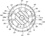
- FIG. 3 is a cross-sectional view taken along the line AA in FIG. 2.
- the present invention is applied to a check valve integrated cut valve in which a cut valve for preventing leakage of fuel to the outside of the fuel tank and a check valve for adjusting the pressure in the fuel tank are integrated. is there.
- the float valve device of the present invention can also be applied to a valve device or the like in which a full tank regulating valve and a check valve are integrated.
- the check valve integrated cut valve 10 (hereinafter referred to as “integrated valve 10”) to which the float valve device of the present invention is applied has an opening 33 a in this embodiment.
- a housing 20 provided with a valve chamber 34 communicating with the inside of the fuel tank below through the partition wall 33, a vent chamber 35 communicating with the outside of the fuel tank on the top, and the valve chamber 34 of this housing 20 can be raised and lowered.
- a check valve 70 which is disposed in the ventilation chamber 35 so as to be movable up and down.
- the housing 20 in this embodiment includes a housing main body 30 having a substantially cylindrical shape, a lower cap 40 attached to a lower opening of the housing main body 30, and an upper portion of the housing main body 30.
- the upper cap 50 is attached to the opening.
- the housing body 30 has a substantially cylindrical peripheral wall 31 having a lower portion 31 b whose diameter is larger than that of the upper portion 31 a, and the partition is placed at a predetermined position above the peripheral wall 31.
- a wall 33 is provided.
- An opening 33a is formed at the center of the partition wall 33, and the lower surface periphery of the opening 33a protrudes.
- the housing main body 30 is formed with the valve chamber 34 on the lower side through the partition wall 33 and the vent chamber 35 on the upper side.
- a plurality of locking holes 31 c are formed at the periphery of the upper opening of the peripheral wall 31, and a plurality of locking recesses 31 d are formed at the upper end of the peripheral wall 31.
- a rib 31e for guiding the raising / lowering operation of the check valve 70 is formed on the inner circumference of the peripheral wall 31 where the vent chamber 35 is formed.
- a plurality of locking projections 31 f are projected from the outer peripheral edge of the lower opening of the peripheral wall 31.
- a plurality of through holes 36 communicating with the inside of the housing body 30 are formed at predetermined intervals along the axial direction above the lower portion 31b of the peripheral wall 31 (see FIGS. 1 and 2).
- a plurality of through holes 36 formed along these axial directions are formed in a plurality of rows at predetermined intervals in the circumferential direction of the peripheral wall 31 (see FIGS. 1 and 4).
- a fuel scattering prevention wall 38 that covers the through hole 36 with a predetermined gap G between the inner periphery of the valve chamber 34 is formed.
- the fuel scattering prevention wall 38 extends downward from the lower end of the upper portion 31 a of the peripheral wall 31, and extends along the circumferential direction of the peripheral wall 31.
- the cross-section along the AA arrow line in FIG. 2 it comprises a second wall portion 38b that connects one end portion of the first wall portion 38a in the circumferential direction and the inner periphery of the lower portion 31b of the peripheral wall 31.
- a substantially L shape is formed, and a gap G is formed between the peripheral wall 31 and the outer peripheral wall 31.
- each of the housing side guide ribs 37 has a length that reaches the upper portion when the float valve body 60 is lowered, and extends from the lower surface of the partition wall 33 to the inner periphery of the upper portion 31 a of the housing body 30. It extends in the axial direction halfway.
- each of the housing side guide ribs 37 has a thin plate shape, has an equal interval along the circumferential direction on the inner periphery of the valve chamber 34, and the protrusion direction tip is the axis S of the housing 20.
- housing-side guide ribs 37 are provided, but two may be provided at opposite positions on the circumference of the valve chamber, or three may be provided at equal intervals in the circumferential direction. Preferably, 6 to 8 are provided at predetermined intervals along the line.
- the lower cap 40 attached to the lower opening of the housing main body 30 has a bottomed cylindrical shape, and a locking hole 41 for locking the locking protrusion 31f of the housing main body 30 to the outer peripheral surface thereof. Is formed.
- the upper cap 50 attached to the upper opening of the housing body 30 has a lid shape whose upper surface is closed, and can be bent through a slit 52 on its peripheral surface.
- a locking claw 53 that locks in the locking hole 31c of the peripheral wall 31 and a locking projection 55 that protrudes from the periphery of the upper end and fits in the locking recess 31d of the peripheral wall 31 are formed.
- An outer case (not shown) is mounted on the outer periphery of the housing 20 having the above structure, and the integrated valve 10 is attached to a fuel tank (not shown) via the outer case. ing.
- the float valve body 60 that can be moved up and down in the valve chamber 34 has a base 61 that is disposed below and an outer diameter smaller than that of the base 61, and is upward from the center of the upper surface of the base 61. And an insertion portion 63 projecting toward the.
- the insertion portion 63 has an outer diameter adapted to the interval W (see FIG. 2) between the plurality of housing-side guide ribs 37, and when the float valve body 60 descends (see FIG. 2) and rises (see FIG. 3).
- the upper portion is formed with a length inserted into the inner periphery of the plurality of housing side guide ribs 37.
- a protrusion 63 a that comes in contact with and separates from the opening 33 a of the partition wall 33 is projected from the center of the upper end of the insertion portion 63 of the float valve body 60.
- a hollow recess 65 is formed at the center of the lower surface of the float valve body 60, and an annular spring accommodating recess 66 is formed on the outer periphery thereof.
- the housing-side guide rib 37 has A plurality of float-side guide ribs 67 extending in the axial direction with a length that does not interfere with each other and formed at predetermined intervals in the circumferential direction are provided. As shown in FIG. 1, the float-side guide rib 67 of the present embodiment protrudes from the lower end to the upper end at an equal interval in the circumferential direction on the outer periphery of the base portion 61.
- eight float-side guide ribs 67 are provided, but two may be provided at opposing positions on the outer periphery of the base 61, or three may be provided at equal intervals in the circumferential direction. It is preferable to provide 6 to 8 pieces at predetermined intervals along the direction.
- the float valve body 60 of this embodiment has a base portion 61 having a large outer diameter and an insertion portion 63 having a smaller outer diameter. There is no particular limitation.
- the float valve body 60 having the above-described shape is accommodated in the valve chamber 34 of the housing body 30, the upper portion of the insertion portion 63 is inserted into the inner periphery of the plurality of housing side guide ribs 37, and the float valve spring 45 is The housing body is housed in the spring housing recess 66 of the float valve body 60, and the other end is supported on the bottom surface of the lower cap 40. In this state, the outer periphery of the lower cap 40 is placed on the outer periphery of the lower opening of the housing body 30.
- the locking cap 31f of the 30 is locked in the locking hole 41 of the lower cap 40, so that the lower cap 40 is attached to the lower opening of the housing body 30, and the float valve body 60 can be moved up and down in the valve chamber 34. It is accommodated (see FIGS. 2 and 3).
- the float valve body 60 when the float valve body 60 is housed in the valve chamber 34 so as to be able to move up and down, it interferes with the housing side guide rib 37 formed on the inner peripheral upper part of the valve chamber 34 of the housing 20 and the housing side guide rib 37 of the float valve body 60.
- the float-side guide rib 67 extending in the axial direction with a length that is not long, there is provided a wide gap region C in which there is no guide rib on either the housing 20 side or the float valve body 60 side.
- the through hole 36 of the housing 20 is formed at a position aligned with the wide gap region C, and the fuel scattering prevention wall 38 is formed.
- the float valve spring 45 is compressed by its own weight, and the float valve body 60 is normally in contact with the bottom surface of the lower cap 40 (see FIG. 2).
- the buoyancy of the float valve body 60 itself is added to the urging force of the float valve spring 45, the float valve body 60 rises, and the projection 63a becomes The opening 33a of the partition wall 33 is closed (see FIG. 3).
- the check valve 70 disposed in the ventilation chamber 35 of the housing 20 includes a casing 71 provided with through holes 71 a and 71 b on both upper and lower surfaces, and the casing 71.
- the valve body 73 is arranged so as to be movable up and down, and mainly includes a built-in spring 75 that urges the valve body 73 toward the upper through hole 71a.
- the check valve 70 is housed in the ventilation chamber 35 of the housing 20 so as to be movable up and down, and comes into contact with and separates from the upper peripheral edge of the opening 33 a of the partition wall 33 of the housing 20.
- the lower end of the check valve biasing spring 77 is brought into contact with the upper surface of the casing 71 of the check valve 70 accommodated in the ventilation chamber 35.
- the engaging protrusion 55 of the upper cap 50 is fitted into the engaging recess 31 d of the housing body 30, and the engaging claw 53 of the upper cap 50 is engaged with the engaging hole 31 c of the housing body 30.
- the upper cap 50 is attached to the upper opening of the housing 20. In this state, the upper end of the check valve urging spring 77 is compressed by the upper cap 50, and the check valve 70 is urged toward the opening 33 a of the partition wall 33 of the housing 20. It is supposed to be blocked.
- the integrated valve 10 to which the float valve device of the present invention is applied is attached to the upper wall of the fuel tank via an external case (not shown) communicating with an evaporation pipe connected to the canister.
- an external case not shown
- the float valve body 60 is lowered and the opening 33a of the partition wall 33 is open (see FIG. 2).
- the opening 33a of the partition wall 33 is closed by the check valve 70 biased by the check valve biasing spring 77 (FIG. 2, FIG. 2). 3).
- the check valve 70 resists the biasing force of the check valve biasing spring 77. rises to open the opening 33a, and the fuel vapor flows into the ventilation chamber 35 through the opening 33a.
- the canister outside the fuel tank or the like passes through the slit 52 (see FIG. 1) of the upper cap 50 or the external case. To reduce the pressure in the fuel tank.
- the pressure in the fuel tank becomes a negative pressure greater than or equal to a predetermined value with respect to the outside air pressure
- the outside air introduced through the outer case or the slit 52 is introduced into the ventilation chamber 35 and the valve body 73 is pressed.
- the valve element 73 moves downward against the urging force of the built-in spring 75 to open the through hole 71a on the upper surface of the check valve, and the outside air passes through the through hole 71b on the lower surface of the check valve and the opening 33a of the housing 20. Is introduced into the valve chamber 34 and flows into the fuel tank, and the negative pressure state in the fuel tank is eliminated.
- the insertion portion 63 of the float valve body 60 is guided by the housing-side guide rib 37 extending to the insertion portion 63 of the float valve body 60, and the inner peripheral surface of the lower portion 31b of the peripheral wall 31 of the housing 20 Since the base 61 of the float valve body 60 is guided by the float side guide rib 67 adjacent to the float, the float valve body 60 can be lifted without tilting, and the projection 63a at the center of the upper end thereof is formed on the lower surface of the opening 33a. It is possible to enhance the sealing performance of the opening 33a by firmly abutting on the side inner periphery.
- the fuel may flow into the valve chamber 34 from the through hole 36 formed in the housing 20.
- a wide gap region C is formed between the housing side guide rib 37 and the float side guide rib 67, where there is no guide rib on either the housing 20 side or the float valve body 60 side.
- the gap between the inner periphery of the valve chamber 34 of the housing 20 and the outer periphery of the float valve body 60 can be secured widely, the fuel that has flowed into the valve chamber 34 from the through hole 36 can be obtained. Therefore, it is possible to prevent the sucked-up behavior, and it is possible to effectively prevent the air from flowing into the ventilation chamber 35 from the opening 33a of the partition wall 33.
- the fuel suction phenomenon can be prevented, it is possible to make it difficult for the fuel to accumulate between the valve chamber 34 of the housing 20 and the float valve body 60, and the fuel is obstructed when the float valve body 60 is moved up and down. Can be prevented, and the dynamic performance of the float valve body 60 can be improved, so that it can be raised and lowered smoothly.
- the fuel that has flowed into the valve chamber 34 from the through hole 36 passes between the wide gap region C and the plurality of float side guide ribs 67 and is sequentially discharged from the hole on the bottom surface of the lower cap 40. It is like that.
- the fuel in the housing 20 can be prevented from flowing into the ventilation chamber 35 from the opening 33a, there is no fear of adversely affecting a canister or the like disposed outside the fuel tank.
- a fuel scattering prevention wall 38 that covers a through hole 36 provided in the wide gap region C with a predetermined gap between the inner periphery of the valve chamber 34 and the inner periphery of the valve chamber 34. Therefore, even if the fuel flows into the housing 20 through the through hole 36, it can be made difficult to collide with the fuel scattering prevention wall 38 and be sucked up, and the opening 33a of the partition wall 33 can be prevented. Can be further prevented from entering the ventilation chamber 35 side. Further, since the fuel scattering prevention wall 38 is disposed in the wide gap region C, even if the fuel scattering prevention wall 38 itself swells due to the fuel flowing into the housing 20, it is pressed or contacted by the float valve body 60. It is possible to prevent the float valve body 60 from moving up and down smoothly.
Landscapes
- Engineering & Computer Science (AREA)
- Mechanical Engineering (AREA)
- General Engineering & Computer Science (AREA)
- Chemical & Material Sciences (AREA)
- Combustion & Propulsion (AREA)
- Life Sciences & Earth Sciences (AREA)
- Sustainable Development (AREA)
- Sustainable Energy (AREA)
- Transportation (AREA)
- Cooling, Air Intake And Gas Exhaust, And Fuel Tank Arrangements In Propulsion Units (AREA)
- Self-Closing Valves And Venting Or Aerating Valves (AREA)
Abstract
La présente invention se rapporte à un dispositif de clapet à flotteur. L'action de levage d'un corps de clapet à flotteur peut être guidée de façon fiable et l'action d'aspiration vers le haut du carburant qui s'est écoulé dans un logement depuis un trou traversant peut être évitée. Ce dispositif à flotteur comprend un logement (20) doté d'une boîte à clapet (34) et d'une chambre de tirage (35) entre lesquelles est disposée une séparation (33) comportant une ouverture (33a), et un corps (60) de clapet à flotteur qui est disposé dans la boîte à clapet (34) de manière à pouvoir se soulever. Plusieurs rainures de guidage (37) côté logement sont disposées dans la partie supérieure de la boîte à clapet (34) sur la périphérie intérieure de celle-ci. Des rainures de guidage (67) côté flotteur se trouvent sur la partie inférieure du corps (60) de clapet à flotteur sur la périphérie extérieure de celui-ci, et sont formées sur une longueur qui n'empiète pas sur les rainures de guidage (37) côté logement lorsque les rainures de guidage (67) côté flotteur viennent en contact avec l'ouverture (33a). Une région de large espace (C) se situe entre les rainures de guidage (37) côté logement et les rainures de guidage (67) côté flotteur, et des trous traversants (36) qui communiquent avec l'intérieur d'un réservoir de carburant sont formés dans la région de large espace (C) du logement (20).
Priority Applications (1)
| Application Number | Priority Date | Filing Date | Title |
|---|---|---|---|
| JP2013505842A JPWO2012127918A1 (ja) | 2011-03-24 | 2012-02-08 | フロート弁装置 |
Applications Claiming Priority (2)
| Application Number | Priority Date | Filing Date | Title |
|---|---|---|---|
| JP2011066495 | 2011-03-24 | ||
| JP2011-066495 | 2011-03-24 |
Publications (1)
| Publication Number | Publication Date |
|---|---|
| WO2012127918A1 true WO2012127918A1 (fr) | 2012-09-27 |
Family
ID=46879086
Family Applications (1)
| Application Number | Title | Priority Date | Filing Date |
|---|---|---|---|
| PCT/JP2012/052842 Ceased WO2012127918A1 (fr) | 2011-03-24 | 2012-02-08 | Dispositif de clapet à flotteur |
Country Status (2)
| Country | Link |
|---|---|
| JP (1) | JPWO2012127918A1 (fr) |
| WO (1) | WO2012127918A1 (fr) |
Cited By (4)
| Publication number | Priority date | Publication date | Assignee | Title |
|---|---|---|---|---|
| WO2016056472A1 (fr) * | 2014-10-07 | 2016-04-14 | 株式会社ニフコ | Clapet de réservoir de carburant |
| JP2019038361A (ja) * | 2017-08-24 | 2019-03-14 | 株式会社パイオラックス | 弁装置 |
| CN110606151A (zh) * | 2018-06-15 | 2019-12-24 | 本田技研工业株式会社 | 油箱盖结构及跨骑型车辆 |
| EP4253809A4 (fr) * | 2020-11-26 | 2024-10-30 | Yingzhi Aiyi Intelligent Automotive Technologies (Jiaxing) Co., Ltd. | Soupape, soupape combinée multifonctionnelle et soupape cflvv |
Citations (5)
| Publication number | Priority date | Publication date | Assignee | Title |
|---|---|---|---|---|
| JP2002285925A (ja) * | 2001-03-26 | 2002-10-03 | Toyoda Gosei Co Ltd | 燃料遮断弁 |
| JP2006234159A (ja) * | 2004-11-24 | 2006-09-07 | Toyoda Gosei Co Ltd | 燃料遮断弁 |
| JP2006321468A (ja) * | 2005-04-20 | 2006-11-30 | Toyoda Gosei Co Ltd | 燃料遮断弁 |
| JP2009166825A (ja) * | 2007-12-18 | 2009-07-30 | Piolax Inc | 燃料漏れ防止弁 |
| JP2010502491A (ja) * | 2006-09-04 | 2010-01-28 | イナジー・オートモーティブ・システムズ・リサーチ・(ソシエテ・アノニム) | 液体タンクの通気回路のためのバルブ |
-
2012
- 2012-02-08 WO PCT/JP2012/052842 patent/WO2012127918A1/fr not_active Ceased
- 2012-02-08 JP JP2013505842A patent/JPWO2012127918A1/ja active Pending
Patent Citations (5)
| Publication number | Priority date | Publication date | Assignee | Title |
|---|---|---|---|---|
| JP2002285925A (ja) * | 2001-03-26 | 2002-10-03 | Toyoda Gosei Co Ltd | 燃料遮断弁 |
| JP2006234159A (ja) * | 2004-11-24 | 2006-09-07 | Toyoda Gosei Co Ltd | 燃料遮断弁 |
| JP2006321468A (ja) * | 2005-04-20 | 2006-11-30 | Toyoda Gosei Co Ltd | 燃料遮断弁 |
| JP2010502491A (ja) * | 2006-09-04 | 2010-01-28 | イナジー・オートモーティブ・システムズ・リサーチ・(ソシエテ・アノニム) | 液体タンクの通気回路のためのバルブ |
| JP2009166825A (ja) * | 2007-12-18 | 2009-07-30 | Piolax Inc | 燃料漏れ防止弁 |
Cited By (7)
| Publication number | Priority date | Publication date | Assignee | Title |
|---|---|---|---|---|
| WO2016056472A1 (fr) * | 2014-10-07 | 2016-04-14 | 株式会社ニフコ | Clapet de réservoir de carburant |
| JP2016075219A (ja) * | 2014-10-07 | 2016-05-12 | 株式会社ニフコ | 燃料タンク用弁装置 |
| JP2019038361A (ja) * | 2017-08-24 | 2019-03-14 | 株式会社パイオラックス | 弁装置 |
| CN110606151A (zh) * | 2018-06-15 | 2019-12-24 | 本田技研工业株式会社 | 油箱盖结构及跨骑型车辆 |
| JP2019217831A (ja) * | 2018-06-15 | 2019-12-26 | 本田技研工業株式会社 | タンクキャップ構造および鞍乗り型車両 |
| US11124061B2 (en) | 2018-06-15 | 2021-09-21 | Honda Motor Co., Ltd. | Tank cap structure and saddle-type vehicle |
| EP4253809A4 (fr) * | 2020-11-26 | 2024-10-30 | Yingzhi Aiyi Intelligent Automotive Technologies (Jiaxing) Co., Ltd. | Soupape, soupape combinée multifonctionnelle et soupape cflvv |
Also Published As
| Publication number | Publication date |
|---|---|
| JPWO2012127918A1 (ja) | 2014-07-24 |
Similar Documents
| Publication | Publication Date | Title |
|---|---|---|
| KR101194726B1 (ko) | 밸브 장치 | |
| JP5091689B2 (ja) | フロート弁装置 | |
| JP5265262B2 (ja) | フロート弁装置 | |
| JP4939120B2 (ja) | 液体遮断弁装置 | |
| JP2009202703A (ja) | 燃料遮断弁 | |
| RU2593328C2 (ru) | Топливный клапан | |
| KR20090079162A (ko) | 체크 밸브 일체형 커트 밸브 | |
| CN103477135B (zh) | 燃料阀 | |
| WO2012127918A1 (fr) | Dispositif de clapet à flotteur | |
| CN102109054B (zh) | 用于液体储箱通气回路的阀门 | |
| JP4767675B2 (ja) | 燃料漏れ防止弁 | |
| US20240255065A1 (en) | Valve device for fuel tank | |
| KR102001780B1 (ko) | 개방형 에어브리더 | |
| CN108138711A (zh) | 燃料箱用通气控制阀 | |
| JP6620511B2 (ja) | 燃料タンク用通気制御弁 | |
| JP5785053B2 (ja) | 弁装置 | |
| JP4206910B2 (ja) | フロートバルブ | |
| JP4881660B2 (ja) | 液体遮断弁装置 | |
| JP2010100117A (ja) | フロート弁装置 | |
| CN116457599B (zh) | 燃料箱用阀装置 | |
| CN114599905B (zh) | 阀装置 | |
| JP4881659B2 (ja) | 液体遮断弁装置 | |
| WO2012118118A1 (fr) | Soupape de coupure de carburant | |
| CN108138710A (zh) | 燃料箱用通气控制阀 | |
| JP6765937B2 (ja) | 燃料タンク用弁装置 |
Legal Events
| Date | Code | Title | Description |
|---|---|---|---|
| 121 | Ep: the epo has been informed by wipo that ep was designated in this application |
Ref document number: 12760306 Country of ref document: EP Kind code of ref document: A1 |
|
| DPE1 | Request for preliminary examination filed after expiration of 19th month from priority date (pct application filed from 20040101) | ||
| ENP | Entry into the national phase |
Ref document number: 2013505842 Country of ref document: JP Kind code of ref document: A |
|
| NENP | Non-entry into the national phase |
Ref country code: DE |
|
| 122 | Ep: pct application non-entry in european phase |
Ref document number: 12760306 Country of ref document: EP Kind code of ref document: A1 |