WO2012127948A1 - Fer à friser - Google Patents
Fer à friser Download PDFInfo
- Publication number
- WO2012127948A1 WO2012127948A1 PCT/JP2012/053769 JP2012053769W WO2012127948A1 WO 2012127948 A1 WO2012127948 A1 WO 2012127948A1 JP 2012053769 W JP2012053769 W JP 2012053769W WO 2012127948 A1 WO2012127948 A1 WO 2012127948A1
- Authority
- WO
- WIPO (PCT)
- Prior art keywords
- hair
- air
- sandwiching
- holding
- air blowing
- Prior art date
- Legal status (The legal status is an assumption and is not a legal conclusion. Google has not performed a legal analysis and makes no representation as to the accuracy of the status listed.)
- Ceased
Links
Images






Classifications
-
- A—HUMAN NECESSITIES
- A45—HAND OR TRAVELLING ARTICLES
- A45D—HAIRDRESSING OR SHAVING EQUIPMENT; EQUIPMENT FOR COSMETICS OR COSMETIC TREATMENTS, e.g. FOR MANICURING OR PEDICURING
- A45D1/00—Curling-tongs, i.e. tongs for use when hot; Curling-irons, i.e. irons for use when hot; Accessories therefor
- A45D1/02—Curling-tongs, i.e. tongs for use when hot; Curling-irons, i.e. irons for use when hot; Accessories therefor with means for internal heating, e.g. by liquid fuel
- A45D1/04—Curling-tongs, i.e. tongs for use when hot; Curling-irons, i.e. irons for use when hot; Accessories therefor with means for internal heating, e.g. by liquid fuel by electricity
-
- A—HUMAN NECESSITIES
- A45—HAND OR TRAVELLING ARTICLES
- A45D—HAIRDRESSING OR SHAVING EQUIPMENT; EQUIPMENT FOR COSMETICS OR COSMETIC TREATMENTS, e.g. FOR MANICURING OR PEDICURING
- A45D1/00—Curling-tongs, i.e. tongs for use when hot; Curling-irons, i.e. irons for use when hot; Accessories therefor
- A45D1/20—External heating means for curling-tongs or curling-irons
-
- A—HUMAN NECESSITIES
- A45—HAND OR TRAVELLING ARTICLES
- A45D—HAIRDRESSING OR SHAVING EQUIPMENT; EQUIPMENT FOR COSMETICS OR COSMETIC TREATMENTS, e.g. FOR MANICURING OR PEDICURING
- A45D20/00—Hair drying devices; Accessories therefor
Definitions
- the present invention relates to a hair iron.
- a hair iron one having a pair of grips rotatably connected at the base end and provided openably and closably, and a pair of sandwiching portions provided opposite to the distal end side of each grip. It is known (for example, refer to patent documents 1).
- an overhanging portion is provided between one grip portion and one holding portion, and a recess is provided at a portion corresponding to the overhanging portion between the other grip portion and the other grip portion. And the blower fan is disposed in the overhang portion.
- a predetermined amount of air is supplied to the sandwiching portion by rotationally driving a blower fan provided in the overhanging portion, and an air generated in the ion generating apparatus disposed in the sandwiching portion is formed in the sandwiching portion Supply to the hair.
- Patent No. 4485118 gazette
- the blower fan is provided between the grip portion and the holding portion, and the air inlet is provided at the root portion of the grip portion. Therefore, the ventilation resistance of the air flow from the intake port to the wind delivery portion becomes large, and there is a problem that the blowing efficiency is not very good.
- an object of this invention is to obtain the hair iron which can improve ventilation efficiency more.
- a first holding unit having a first hair holding surface
- a second holding unit having a second hair holding surface
- the first hair holding surface A hair iron for holding hair with a second hair holding surface
- a blower is provided on the back side of the first hair holding surface in the first holding portion, and an outer surface of the first holding portion is provided.
- the gist is that an air inlet for introducing outside air is formed in a portion other than the first hair gripping surface.
- a hair winding portion for winding hair is formed on the back side of the first hair holding surface in the first holding portion, and the air inlet is formed in the hair winding portion.
- the air blowing unit includes an air blowing mechanism for blowing air by rotation, the air inlet is formed in a long hole shape, and the air hole in the long hole shape has both ends,
- the gist is that the air flow toward the rotation center of the air blowing mechanism is formed on the boundary of the area where the air flow is formed or outside the area.
- the air blowing mechanism includes a fan having a shaft portion and a blade portion, and a region where an air flow toward the rotation center of the air blowing mechanism is the first holding portion A conical surface formed on the outer surface when the straight line connecting the root side center of the shaft of the fan and the tip of the blade of the fan is rotated with respect to the rotation axis of the blower mechanism and the outer surface of the first sandwiching portion
- the gist is that the region is surrounded by the line of intersection with the
- the air suction unit is provided on the back side of the first hair holding surface in the first holding unit, and the outside air is introduced to a portion of the first holding unit outer surface other than the first hair holding surface. It has a mouth.
- the ventilation resistance of the air flow can be reduced by providing the air blowing portion and the air intake port on the back side of the first sandwiching portion, and the air flow resistance can be reduced when supplying air from the air blowing portion to the hair. Can be suppressed, and as a result, the air blowing efficiency of the hair iron can be further improved.
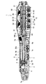
- FIG. 6 is an enlarged cross-sectional view of a portion corresponding to FIG. 5; It is a figure which shows the air blower opening concerning one Embodiment of this invention, Comprising: It is the figure which looked at the upper arm part from the upper side hair pinching surface side.
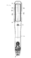
- the hair iron 1 as shown in FIG. 1, includes an upper arm 2 and a lower arm 3 which are connected so as to be able to expand in a substantially V shape via a pivot connection 4. There is. Then, by rotating the upper arm 2 and the lower arm 3 relative to each other via the rotational connection 4, the tips of the upper arm 2 and the lower arm 3 can be made to contact or separate. . That is, in the present embodiment, the upper hair holding surface 22a and the lower hair holding surface 32a, which will be described later, are brought into contact with or separated from each other as the upper arm 2 and the lower arm 3 rotate relative to each other.
- the cylindrical portion 2 c opened downward is provided in the vicinity of the pivot connection portion 4 of the upper arm portion 2, and the pivot connection of the lower arm portion 3
- a cylindrical portion 3 c which is open upward and can be inserted into the cylindrical portion 2 c.
- a coil spring 5 is accommodated in a space formed by the cylindrical portion 2c and the cylindrical portion 3c, and the upper arm portion 2 and the lower arm portion 3 are mutually expanded by the coil spring 5 It is urged to do.
- the cylindrical portion 3c into the cylindrical portion 2c when the hair iron 1 is closed, the upper arm portion 2 and the lower arm portion 3 are prevented from being displaced in the width direction.
- rotation of the upper arm 2 and the lower arm 3 in the expanding direction is restricted by a stopper (not shown).
- the upper grip (first grip) 2a and the lower grip (second A grip portion 3a is provided on the side of the rotational connection 4 of the upper arm 2 and the lower arm 3 (rear side of the hair iron 1).
- the upper grip (first grip) 2a and the lower grip (second A grip portion 3a is provided on the side of the rotational connection 4 of the upper arm 2 and the lower arm 3 (rear side of the hair iron 1).
- An upper holding portion (first holding portion) 2b and a lower holding portion (second holding portion) 3b are provided on the tip end side.
- the upper gripping portion 2b and the lower gripping portion 3b are pivoted so as to close the upper arm 2 and the lower arm 3, respectively, the upper hair gripping surface (first hair gripping surface (first hair gripping) Surface) 22a and a lower hair holding surface (second hair holding surface) 32a.
- curled portions 2d and 3d for curling the hair on the outer surface of the holding portion in the present embodiment, the outer surface of each of the upper holding portion 2b and the lower holding portion 3b.
- the outer surfaces of the upper gripping portion 2b and the lower gripping portion 3b are the upper hair gripping surface 22a and the lower hair gripping surface 32a of the outer surfaces of the upper gripping portion 2b and the lower gripping portion 3b. Refers to the face that exists on the back side of That is, in FIG.
- the outer surface of the upper holding portion 2b other than the lower surface, and the outer surface of the lower holding portion 3b other than the upper surface are the outer surface of the upper holding portion 2b and the outer surface of the lower holding portion 3b, respectively. It corresponds to the surface.
- the upper holding portion 2 b and the lower holding portion 3 b are provided with a heater 23 and a heater 33 as heat generating portions.
- the hair is sandwiched between the upper hair holding surface 22a and the lower hair holding surface 32a, and the heat generated by the heater 23 and the heater 33 is applied to the hair through the upper hair holding surface 22a and the lower hair holding surface 32a. So, the hair is curled or straight.
- curling of hair is performed as follows. First, the heated upper holding unit 2b and the lower holding unit 3b are made to face each other. And, in a state where the hair is arranged to extend in the width direction of the upper sandwiching part 2b and the lower sandwiching part 3b between the upper sandwiching part 2b and the lower sandwiching part 3b, the upper hair sandwiching surface 22a and the lower The hair is sandwiched by the side hair pinching surface 32a. Next, the hair iron 1 is rotated in a state in which the hair is sandwiched, and the hair on the root side not sandwiched by the upper hair clamping surface 22a and the lower hair clamping surface 32a is pressed against the curled portion 2d or the curled portion 3d. .
- curling is applied to the hair by sliding the hair iron 1 along the hair and pulling it toward the end of the hair.
- the straight-shaped brushing to the hair is directed to the end of the hair while sliding along the hair without rotating the hair iron 1 having the hair held between the upper hair holding surface 22a and the lower hair holding surface 32a. It is done by pulling down.
- the hair iron 1 performs hair setting by applying heat to the hair.
- the upper arm portion 2 and the lower arm portion 3 described above mainly include a case 20 and a case 30 forming an outer wall, and a case 20 and a case 30 have a cavity formed therein. Electrical parts are housed.
- a protrusion 20d provided on the upper end of the lower case 20b opened upward is engaged with a recess 20c provided on the lower end of the upper case 20a opened downward, welding or welding
- the upper case 20a and the lower case 20b are integrated by bonding or screws.
- a case 20 having a cavity formed therein is formed.
- a protrusion 30d provided on the lower end side of the upper case 30a opened downward is fitted in a groove 30c provided on the upper end side of the lower case 30b opened upward, and welding is performed.
- the upper case 30a and the lower case 30b are integrated by bonding, screws, or the like.
- a case 30 having a cavity formed therein is formed.
- the hair pinching member 21 having the upper hair pinching surface 22a and the hair pinching member 31 having the lower hair pinching surface 32a are supported by the case (sandwich body) 20 and the case (sandwich body) 30. I am doing it.
- the upper holding unit (first holding unit) 2b and the lower holding unit (second holding unit) 3b are supported by supporting the hair holding member 21 and the hair holding member 31 in the case 20 and the case 30, respectively.
- the hair gripping member 21 and the hair gripping member 31 have a plate portion 22 and a plate portion 32 having a substantially plate-like shape, and on the surface of the plate portion 22 and the plate portion 32, substantially flat upper hair A sandwiching surface 22a and a lower hair sandwiching surface 32a are formed.
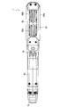
- the upper hair pinching surface 22a and the lower hair pinching surface 32a are formed in a substantially rectangular shape elongated in the longitudinal direction of the case 20 in plan view, as shown in FIG.
- both end portions in the width direction are bent toward the inside of the case 20 and the case 30.
- curved surface 22d and curved surface 32d which become convex toward the diagonal outside in width direction sectional view are shown in Drawing 3 in the cross direction both ends of upper hair pinching surface 22a and lower hair pinching surface 32a.
- a housing portion 24 and a housing portion 34 for housing the heater 23 and the heater 33 are formed on the back side of the upper hair pinching surface 22a and the lower hair pinching surface 32a of the plate portion 22 and the plate portion 32.
- the plate portions 22 and 32 are configured by the hair sandwiching side plates 22b and 32b and the back side plates 22c and 32c, and the hair sandwiching side plates 22b and 32b and the back side plates 22c and 32c are used.
- the formed space is the accommodating portion 24, 34.
- the heaters 23 and the heaters 33 housed in the housing portion 24 and the housing portion 34 are in contact with the inner surfaces of the plate portion 22 and the plate portion 32, respectively.
- the plate portion 22 and the plate portion 32 are preferably made of, for example, a material having high thermal conductivity such as copper or aluminum so that heat can be easily transmitted to the hair.
- a PTC heater Pulsitive Temperature Coefficient heater
- the heater 23 and the heater 33 use a PTC heater as an example in the present embodiment, the present invention is not limited to this, and a nichrome wire heater or other heating means may be used.
- the heater heat generating unit
- the heater may be provided only in one of the upper holding unit (first holding unit) 2b and the lower holding unit (second holding unit) 3b.
- a plurality of ion generators 10 are provided in the inside of the sandwiching portion (second sandwiching portion 3 b) of the case 30.
- four ion generators 10 are provided along the longitudinal direction at both widthwise end portions of the second sandwiching portion 3b.
- a mist generator that generates mist or a metal particle generator that generates metal particles can be used.
- mist generating device a device for applying high voltage to the discharge electrode 11 from the high voltage generation circuit with reference to the ground electrode 12 to generate discharge (such as corona discharge) and atomizing dew condensation water by the discharge action It can be used.
- discharge such as corona discharge
- cooling plate which consists of a member (for example, metal member etc.) which has a Peltier element and heat conductivity, and a radiating fin which radiates away the heat generated at the time of cooling a cooling plate.
- a member for example, metal member etc.
- a radiating fin which radiates away the heat generated at the time of cooling a cooling plate.
- a device that generates a discharge (such as corona discharge) by applying a high voltage to the discharge electrode 11 from the high voltage generation circuit with reference to the ground electrode 12 can be used.
- a discharge such as corona discharge
- metal particles such as metal molecules and ions
- the discharge electrode 11 of the metal particle generator is plated with a transition metal (eg, gold, silver, copper, platinum, zinc, titanium, rhodium, palladium, iridium, ruthenium, osmium, etc.) alone, an alloy, or a transition metal. It is possible to comprise by the processed member etc.
- a transition metal eg, gold, silver, copper, platinum, zinc, titanium, rhodium, palladium, iridium, ruthenium, osmium, etc.
- the antibacterial action can be generated by the metal fine particles.
- platinum, zinc, titanium or the like is contained in the fine particles of metal, the fine particles of the metal can produce an antioxidant effect.
- fine particles of platinum have a very high antioxidative effect.
- a portion for example, a ground electrode or the like
- which does not release the metal fine particles can be configured using stainless steel, tungsten, or the like.
- the discharge unit generates ions (for example, negative ions, for example, NO2-, NO3-, etc.) by a discharge action, and this ion is used as a discharge electrode, a ground electrode, a member containing other metal materials or metal components,
- ions for example, negative ions, for example, NO2-, NO3-, etc.
- the metal particles may be generated by collision. That is, the ground electrode or the other member may be made of the material containing the transition metal, and metal fine particles may be released therefrom.
- a control circuit 6a for controlling the temperature of the heater 23 and the heater 33 is accommodated in the case 30, and the heater 23 and the heater 33 are connected to the control circuit 6a through the lead wire 8. .
- the temperatures of the upper hair pinching surface 22a and the lower hair pinching surface 32a can be set stepwise.
- a power cord (not shown) is pulled out from the rear end portion 1 a of the hair iron 1.
- the operation switch 7 is provided on the lower grip 3 a side of the case 30.
- the operation switch 7 By operating the operation switch 7, it is possible to switch on / off of the current supply to the heater 23 and the heater 33. It has become.
- the heater 23 and the heater 33 are energized by the operation of the operation switch 7, the heater 23 and the heater 33 generate heat. Then, the heat is transmitted from the heater 23 and the heater 33 which generate heat to the plate portion 22 and the plate portion 32, whereby the plate portion 22 and the plate portion 32 are heated.
- the thermistor 73 is attached to the plate portion 22 and the back surfaces 22 e and 32 e of the plate portion 32, and changes with the temperature change of the heaters 23 and 33.
- the temperatures of the heater 23 and the heater 33 are controlled using the resistance value.
- Reference numeral 74 denotes a fuse.
- a temperature control switch 7a is provided on the lower grip portion 3a side of the case 30, and by operating the temperature control switch 7a, the set temperature of the upper hair pinching surface 22a and the lower hair pinching surface 32a Can be switched.
- the case 30 is provided with five lighting units 71 that are lighted by an LED lamp (not shown).
- the current setting temperature can be recognized by lighting the lighting units 71 corresponding to each step. I have to.
- the hair iron 1 is provided with the control member which controls the relative movement to the lower side holding part 3b side of the upper side holding part 2b.
- a stopper projection 40 projecting upward is provided at the lower portion of the lower grip 3a of the case 30, and a stopper groove 41 is provided in the lower case 20b of the case 20, and the tip of the stopper projection 40 is a stopper It is made to abut on the bottom of the groove 41.
- At least one of the hair gripping members 21 and 31 is supported so as to be relatively reciprocally movable in the vertical direction (the normal direction of the hair gripping surface) with respect to the case (clipping portion main body) 20 and 30. preferable.
- the hair gripping members 21 and 31 can be case 20 , 30 can be moved up and down.
- the blower unit 50 is provided above the upper hair pinching surface 22a of the upper pinching portion (first pinching portion) 2b (the back side of the first hair pinching surface).
- the upper pinching portion (first pinching portion) 2 b includes a hair pinching unit 25 having an upper hair pinching surface (first hair pinching surface) 22 a.
- the ventilation unit 51 which has the ventilation part 50 is provided in the upper part (The opposite side to the 1st hair clamping surface in a hair clamping unit) of the hair clamping unit 25. As shown in FIG.
- a heat insulating portion is interposed between the upper hair holding surface (first hair holding surface) 22 a and the blower 50.
- the ceiling wall 25a of the hair nipping unit 25, that is, the upper nipping portion (first nipping portion) 2b side of the upper case 20a is heat resistant such as polybutylene terephthalate (PBT) or polyphenylene sulfide (PPS) It is made of a plastic resin.
- the heat insulating portion may be formed by interposing a heat insulating material such as felt between the upper hair holding surface (first hair holding surface) 22 a and the blower unit 50.
- a substantially horizontal flat portion 20e is formed at the rear of the upper grip portion 2a, and an inclined portion 20f is formed at the front end of the flat portion 20e.
- the top wall 25a of the hair gripping unit 25 is formed at the front end of the upper case 20a by bending the crank 20 downward from the front end of the inclined portion 20f.
- the top wall portion of the hair gripping unit 25 is formed to be located below the flat portion 20e. That is, the hair gripping unit 25 is formed so as to be thinner in the vertical direction.
- the hair gripping unit 25 is formed so as to be thinner, the air blowing space can be reduced while suppressing an increase in the overall thickness of the upper gripping portion (first gripping portion) 2b. I try to secure as much as possible.
- the air blowing unit 51 includes an air blowing unit 50, and an outer shell 52 covering the upper side of the air blowing unit 50 and forming an outer shell of the upper holding unit (first holding unit) 2b.
- the blower unit 50 includes a blower mechanism (a blower mechanism that performs blower blowing by rotation) 53 and a partition 54 that covers the outer periphery of the blower mechanism 53.
- the blower mechanism 53 is formed by connecting the fan 55 to a motor shaft of a motor (not shown), and the blower mechanism 53 is attached to the partition wall 54.
- the fan 55 is composed of a shaft 55a connected to the motor shaft and a plurality of blades 55b formed on the side of the shaft 55a.
- blower mechanism 53 an axial fan, a sirocco fan, a turbo fan, a cross flow fan or the like can be used.
- two air blowing mechanisms 53 are juxtaposed in the longitudinal direction of the upper sandwiching portion (first sandwiching portion) 2b, and the outer periphery of each fan 55 is a partition 54 having a substantially rectangular shape in plan view. Is covered.
- the air blowing mechanism 53 is supported by the hair gripping unit 25 by attaching the partition 54 to the rib 26 provided on the top wall 25 a of the hair gripping unit 25.
- the outer shell 52 has side walls 52a extending downward and outward at both ends in the widthwise direction in a front view, and a curled portion (hair winding portion) 52b around which hair is wound is formed at the center in the widthwise direction. It has a shape having a convex curved surface upward. That is, in the present embodiment, the curled portion 52b is formed on the back side (upper side in FIG. 3) of the upper hair pinching surface (first hair pinching surface) 22a in the upper pinching portion (first pinching portion) 2b. The curled portion 52b corresponds to the curled portion 2d of the upper holding portion 2b.
- the outer housing 52 is supported by the columns 28 provided at the four corners of the top wall 25a of the hair gripping unit 25 so that the upper gripping portion (first gripping portion) having the hair gripping unit 25 and the blower unit 51 ) 2b is formed.
- the outer shell 52 is formed slightly wider than the hair gripping unit 25. Specifically, both widthwise ends 52 c of the outer shell 52 protrude downward and outward from the top wall 25 a of the hair gripping unit 25.
- a gap is formed between the outer housing 52 and the hair holding unit 25 by projecting both widthwise ends 52c of the outer housing 52 downward and outward relative to the top wall 25a of the hair holding unit 25.
- the gap is a blower 60.
- the air sent from the air blowing mechanism 53 to the air blowing port is discharged from the air blowing port 60 to the outside. At this time, the wind sent from the blowing mechanism 53 is discharged downward and outward, and the wind is more efficiently applied to the hair sandwiched between the upper hair holding surface 22 a and the lower hair holding surface 32 a ( Cooling air can be supplied.
- both widthwise ends 52c of the outer shell 52 are better than the top wall 25a of the hair pinching unit 25 so as to maintain the outer surface of the outer shell 52.
- the hair clipper unit 25 is equipped.
- the air blowing port 60 is formed to extend in the longitudinal direction on both ends in the width direction of the hair gripping unit 25.
- the air outlets 60 are formed on both ends in the width direction of the hair nipping unit 25, the second ends on both ends in the longitudinal direction of the hair nipping unit 25 and in the center in the width direction of the hair nipping unit 25.
- the air outlet 61 may be formed.
- the inlet 52d is formed to introduce the The air inlet 52 d is for improving the air blowing efficiency of the air blowing unit 51.
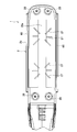
- an air inlet 52 d for introducing outside air into the air blowing unit 51 is formed in the curled portion (hair wound portion) 52 b formed at the center in the width direction of the outer shell 52.
- the air blowing mechanism 53 is driven (including aging to be described later)
- the outside air in the vicinity of the air inlet 52d is introduced into the upper sandwiching portion 2b from the air inlet 52d and sent to the air blowing port 60 by the air blowing mechanism 53 for blowing air.
- a series of wind flows are generated that are emitted from the outside 60.
- the intake port 52d is formed of a plurality of long holes (long hole-like intake ports) extending in the longitudinal direction of the upper sandwiching portion (first sandwiching portion) 2b.
- Each air inlet (long-hole-like air inlet) 52 d is formed such that both ends thereof exist on the boundary line of the region R1 where the air flow toward the rotation center of the blower mechanism 53 is formed or outside the region R1. There is.
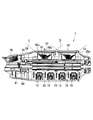
- a straight line L connecting the root side center of the shaft portion 55a of the fan 55 (axis center of the air blowing mechanism: rotation center of the air blowing mechanism) and the tip of the blade portion 55b of the fan 55 An area surrounded by a line of intersection C1 between the conical surface D and the outer surface of the upper holding portion 2b, which is formed when it is rotated with respect to the rotation axis A), is defined as an area R1.
- each intake port (long-hole shaped intake port) 52d is formed in the region R1, and both ends are present on the intersection C1 or outside the region R1. It is formed.
- each intake port (long-hole shaped intake port) 52d are illustrated as extending in the vertical direction, but in each intake port (long-hole shaped intake port) 52d
- Each intake port (long hole intake port) 52 d may be formed such that the inner side surfaces at both ends extend substantially in parallel with the straight line L. In this way, it can be suppressed that the inner side surface of each intake port (long-hole shaped intake port) 52d becomes a draft resistance at the time of the introduction of the outside air, and the outside air can be introduced more efficiently.
- the curvature of the curled portion 52b is made relatively small so as to be a gentle curved surface, so the line of intersection C1 between the conical surface D and the outer surface of the upper holding portion 2b is approximately circular. Become. Accordingly, the line of intersection C1 between the conical surface D and the outer surface of the upper holding portion 2b is substantially concentric with the locus (circumference C2) described by the tip 55c of the blade 55b when the fan 55 is rotated See Figure 5).
- the straightening vanes 27 are provided on the side opposite to the upper hair holding surface (first hair holding surface) 22 a in the hair holding unit 25.
- the shape of the straightening vanes 27 is preferably set so as not to disturb the flow of the delivery wind formed by an arbitrarily selected fan.
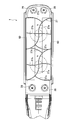
- the straightening vanes 27 are arranged on the top surface of the top wall 25a of the hair gripping unit 25 as shown in FIG. Preferably, they are integrally formed so as to extend radially.
- the straightening vanes 27 may be provided separately from the top wall 25 a of the hair gripping unit 25.
- the straightening vanes 27 have a shape shown in FIG.
- the straightening vane 27 is formed so as to project forward in the direction in which the wind formed when the fan 55 is rotated flows.
- the wind in the region (upper right and lower left regions in FIG. 10) of the hair pinching unit 25 is in the region (the upper right and lower left region in FIG.
- the straightening vane 27a is provided so as to flow to one width side (the wind in the upper right of FIG. 10 is on the right and the wind in the lower left region is on the left). That is, in FIG. 10, the straightening vanes 27a are provided so as to have a gentle S-shape from the upper right to the lower left in plan view.
- a straightening vane 27b is provided from one end to the other end in the width direction so as to have a more gentle S-shape.
- the straightening vane 27b extending in the width direction is a region where the tangent drawn to the front of the flow of the wind from the contact points toward one width-direction end of the hair gripping unit 25 rather than the contact point (the lower right and upper left regions in FIG. Is provided in order to efficiently flow the wind in the width direction at one end side in the width direction.
- the longitudinal direction in the area (the lower right and upper left areas in FIG. 10) of the tangent of each blowing mechanism 53 drawn forward of the flow of the wind from the contact point toward one end in the width direction of the hair gripping unit 25 than the contact point.
- the straightening vanes 27 c are provided to prevent the wind in the region from flowing in the longitudinal direction.
- the air volume of the cooling air flowing from each portion of the air blowing port 60 extending in the longitudinal direction can be more uniformly and efficiently blown. become able to.
- the height of the straightening vanes 27 is preferably as high as possible.
- the straightening vanes 27 are preferably grounded to the lower surface of the blower mechanism 53.
- a control circuit 6 b for controlling the rotation of the fan (the air blowing mechanism 53) and the like is accommodated in the case 20, and the air blowing mechanism 53 is accommodated in the control circuit 6 b via the lead wire 8. It is connected.
- a cooling button 75 is provided on the inclined portion 20f of the case 20. By operating the cooling button 75, the number of rotations of the fan (the air blowing mechanism 53) can be switched. That is, by operating the cooling button 75, the blower mechanism 53 can be switched between the normal operation state and the other state (the blower mechanism 53 is in a stopped state or an aging state described later). ing.
- the user when the temperature around and inside the upper holding portion 2b and the lower holding portion 3b rises, the user may be burned by skin contact or the user may feel the heat during use. It occurs. Moreover, since the temperature of the wind sent from the air blower 60 rises, the temperature difference can not be given to the hair, and there is a problem that the cooling effect of the hair itself and hence the hair setting efficiency are lowered.
- control circuit 6b rotates the fan 55 when the thermistor 73 described above is used as a detector and the thermistor 73 detects that the temperature of the heater 23 and the heater 33 has reached a predetermined temperature or more. Let me do it and let me age.
- the hair iron 1 is a thermistor (detector) 73 that detects the temperature of the heater 23 and the heater 33 (heat generating portion), and a control circuit that performs aging of the blower 50 based on the detected temperature of the heater 23 and the heater 33 And (control unit) 6b.
- the detection of the predetermined temperature may not be a thermistor type that detects the temperature itself.
- a predetermined temperature is detected by detecting load current values of the heater 23 and the heater 33 installed as heat sources, determining a correlation between a predetermined temperature and time, and detecting a time obtained from the correlation. You may do it.
- the blower unit 50 when the temperatures of the heater 23 and the heater 33 exceed 100 ° C., the blower unit 50 is aged.
- the temperature in the air blowing portion 50 exceeds 40 ° C. Therefore, when the temperature of the heater 23 and the heater 33 exceeds 100 ° C., the air blowing unit 50 is aged to secure a predetermined air flow rate, and the temperature in the air blowing unit 50 is 40 ° C. or less It is made to keep close temperature condition).
- the heater 23 and the heater 33 are energized, and the upper hair holding surface 22a and the lower hair holding surface 32a are heated to a predetermined temperature (for example, 170 ° C.) .
- the control circuit 6b rotates the fan 55 when the temperature of the heater 23 and the heater 33 detected by the thermistor 73 exceeds 100 ° C. as the temperature of the upper hair sandwiching surface 22a and the lower hair sandwiching surface 32a increases. Aging will be done.
- the cooling button 75 is operated to increase the number of rotations of the fan 55, and the blower mechanism 53 is brought into the normal operation state. Do.
- the temperature rise in the blower unit 50 is suppressed by rotating the fan 55 to perform aging, the temperature rise of the cooling air blown to the outside from the air blowing port 60 is suppressed, and the temperature of the cooling air is determined. It can be brought closer to the outside temperature.
- the upper hair sandwiching surface 22a and the lower hair holding surface 32a sandwich the hair.
- hydrogen bonds between the hair fibers are cut.
- the hair iron 1 is rotated by half while holding the hair, and the hair on the root side not held by the upper hair holding surface 22a and the lower hair holding surface 32a is wound around the curled portion (hair winding portion) 52b. .
- hair in a state in which hydrogen bonds between hair fibers are broken by heat is wound around the curled portion (hair wound portion) 52b. Therefore, the hair can be easily curled. Furthermore, since the hair that has been trimmed to a desired shape in a state in which hydrogen bonds between hair fibers are cut by heat is cooled by the cooling air blown from the vicinity of the heating unit, the hair is trimmed in a desired shape. The fibers can be more rapidly hydrogen bonded. Therefore, the curl retention of hair can be further enhanced.
- the air blower 50 is provided on the back side of the upper hair pinching surface (first hair pinching surface) 22a in the upper pinching portion (first pinching portion) 2b.
- An air inlet 52d for introducing outside air is formed in a portion of the outer surface of the first sandwiching portion 2b other than the upper hair sandwiching surface (first hair sandwiching surface) 22a.
- the ventilation resistance of the air flow can be reduced by providing the air blowing unit 50 and the air inlet 52d on the back side of the upper holding unit (first holding unit) 2b, so that the air from the air blowing unit 50 to the hair can be reduced.
- it can suppress that the draft resistance of air flow increases, As a result, the ventilation efficiency of the hair iron 1 can be improved more.
- the air blowing amount can be further increased when the air blowing portion having the same size as that of the conventional one is provided, and the air volume equivalent to the conventional In the case of sending out the air, it is possible to miniaturize the blower 50.
- the air can be blown even with the low output operation, the noise at the time of driving the air blowing unit 50 can be reduced.
- an air inlet 52 d for introducing outside air into the air blowing unit 51 is formed in the curled portion (hair wound portion) 52 b formed at the center in the width direction of the outer shell 52.
- the cooling effect of the hair can be further enhanced. That is, the hair heated and heated by the upper sandwiching part 2b and the lower sandwiching part 3b (first and second sandwiching parts) at the time of curling treatment by the external air introduced from the air inlet 52d provided in the curled part 52b Can be cooled more rapidly. Thereby, damage to the hair can be reduced, and sensory effects such as moistness, scaly feel, touch, and softness of the hair can be further improved.
- an air inlet 52d for introducing outside air into the air blowing unit 51 is formed in the curled portion (hair wound portion) 52b formed at the center in the width direction of the outer shell 52, whereby the air inlet 52d, air blowing mechanism 53 and The blower ports 60 are arranged in this order in the vertical direction (the thickness direction of the upper holding portion). That is, when the blower mechanism 53 is driven, outside air in the vicinity of the intake port 52d positioned above is introduced into the upper sandwiching portion 2b from the intake port 52d, and sent to the blower port 60 by the blower mechanism 53 positioned therebelow. A series of wind flows are formed that are discharged to the outside from the lowermost air outlet 60. Therefore, it is possible to shorten and straighten the flow of the wind, it is possible to further reduce the pressure loss of the cooling air, and it is possible to further improve the blowing efficiency of the cooling air.
- the intake port 52d is formed of a plurality of long holes (long hole-like intake ports) extending in the longitudinal direction of the upper sandwiching portion (first sandwiching portion) 2b.
- Each air inlet (long-hole-like air inlet) 52 d is formed such that both ends thereof exist on the boundary line of the region R1 where the air flow toward the rotation center of the blower mechanism 53 is formed or outside the region R1. There is. Therefore, there is no site that inhibits the introduction of the outside air to each air intake port (long hole shaped air intake port) 52d, and the outside air can be introduced more efficiently.
- the temperature of the shell housing 52 can be lowered with higher efficiency by enhancing the suction and discharge efficiency of the air blowing mechanism 53, and the hair cooling effect can be further enhanced.
- this invention it is also possible to apply this invention to the hair iron apparatus in which ion production
- the hair iron which provided the straightening vane was illustrated, but the structure of a hair iron is not limited to this .
- the present invention can be applied even to a hair iron in which the heat insulating portion is interposed between the upper hair holding surface and the air blowing portion, but the straightening vane is not provided. .
- the present invention can be applied even to a hair iron in which a heat insulating portion is not interposed between the upper hair holding surface and the air blowing portion. It is also possible to provide a straightening vane in the configuration of FIG.
- the specifications (shape, size, layout, etc.) of the hair holding surface, the grip portion, the air outlet, and other details can be appropriately changed.
Landscapes
- Cleaning And Drying Hair (AREA)
Abstract
L'invention concerne un fer à friser (1) ayant une première bride de maintien (2b) ayant une première surface de maintien pour cheveux (22a), et une deuxième bride de maintien (3b) ayant une seconde surface de maintien pour cheveux (32a). Les cheveux sont pris en sandwich entre la première surface de maintien pour cheveux (22a) et la seconde surface de maintien pour cheveux (32a). Une souffleuse d'air (50) se trouve au niveau du côté arrière de la première surface de maintien pour cheveux (22a) dans la première bride de maintien (2b). Un orifice d'admission d'air (52d), qui fait rentrer de l'air extérieur, se trouve en une position autre que la première surface de maintien pour cheveux (22a) sur l'extérieur de la première bride de maintien (2b).
Priority Applications (1)
| Application Number | Priority Date | Filing Date | Title |
|---|---|---|---|
| CN2012800117616A CN103402391A (zh) | 2011-03-23 | 2012-02-17 | 烫发器 |
Applications Claiming Priority (2)
| Application Number | Priority Date | Filing Date | Title |
|---|---|---|---|
| JP2011063545A JP2012196359A (ja) | 2011-03-23 | 2011-03-23 | ヘアーアイロン |
| JP2011-063545 | 2011-03-23 |
Publications (1)
| Publication Number | Publication Date |
|---|---|
| WO2012127948A1 true WO2012127948A1 (fr) | 2012-09-27 |
Family
ID=46879111
Family Applications (1)
| Application Number | Title | Priority Date | Filing Date |
|---|---|---|---|
| PCT/JP2012/053769 Ceased WO2012127948A1 (fr) | 2011-03-23 | 2012-02-17 | Fer à friser |
Country Status (3)
| Country | Link |
|---|---|
| JP (1) | JP2012196359A (fr) |
| CN (1) | CN103402391A (fr) |
| WO (1) | WO2012127948A1 (fr) |
Cited By (1)
| Publication number | Priority date | Publication date | Assignee | Title |
|---|---|---|---|---|
| US12127656B2 (en) | 2019-03-22 | 2024-10-29 | Dyson Technology Limited | Hair styling appliance |
Families Citing this family (2)
| Publication number | Priority date | Publication date | Assignee | Title |
|---|---|---|---|---|
| JP6624392B2 (ja) * | 2016-12-26 | 2019-12-25 | パナソニックIpマネジメント株式会社 | ヘアーアイロン |
| CN209547305U (zh) * | 2018-12-19 | 2019-10-29 | 东莞市丹业电器有限公司 | 一种多功能快速卷、直发器 |
Citations (2)
| Publication number | Priority date | Publication date | Assignee | Title |
|---|---|---|---|---|
| JPS62123702U (fr) * | 1986-01-28 | 1987-08-06 | ||
| JP2009050681A (ja) * | 2007-08-02 | 2009-03-12 | Futek Inc | ヘアーアイロン |
Family Cites Families (3)
| Publication number | Priority date | Publication date | Assignee | Title |
|---|---|---|---|---|
| JP3568949B2 (ja) * | 2004-04-19 | 2004-09-22 | 九州日立マクセル株式会社 | 髪処理装置 |
| KR100597887B1 (ko) * | 2004-11-01 | 2006-07-06 | (주) 케이.아이.씨.에이 | 송풍기능을 가지는 헤어용 아이론 |
| KR20100010088A (ko) * | 2008-07-22 | 2010-02-01 | 신진전자주식회사 | 냉온 모발 성형용 가열기 |
-
2011
- 2011-03-23 JP JP2011063545A patent/JP2012196359A/ja not_active Withdrawn
-
2012
- 2012-02-17 CN CN2012800117616A patent/CN103402391A/zh active Pending
- 2012-02-17 WO PCT/JP2012/053769 patent/WO2012127948A1/fr not_active Ceased
Patent Citations (2)
| Publication number | Priority date | Publication date | Assignee | Title |
|---|---|---|---|---|
| JPS62123702U (fr) * | 1986-01-28 | 1987-08-06 | ||
| JP2009050681A (ja) * | 2007-08-02 | 2009-03-12 | Futek Inc | ヘアーアイロン |
Cited By (1)
| Publication number | Priority date | Publication date | Assignee | Title |
|---|---|---|---|---|
| US12127656B2 (en) | 2019-03-22 | 2024-10-29 | Dyson Technology Limited | Hair styling appliance |
Also Published As
| Publication number | Publication date |
|---|---|
| JP2012196359A (ja) | 2012-10-18 |
| CN103402391A (zh) | 2013-11-20 |
Similar Documents
| Publication | Publication Date | Title |
|---|---|---|
| EP2856905A1 (fr) | Sèche-cheveux apte à ajuster le volume d'air non chauffé déchargé en même temps que l'air chaud | |
| CN104970533B (zh) | 加热送风装置 | |
| CN208129714U (zh) | 一种红外加热吹风筒 | |
| KR100990032B1 (ko) | 헤어드라이어 | |
| JP3594961B2 (ja) | 髪処理装置 | |
| CN108634527B (zh) | 卷发冷却定型一体式卷发器 | |
| CN210747781U (zh) | 一种多功能电动卷发直发器 | |
| CN208610056U (zh) | 卷发冷却定型一体式卷发器 | |
| JPS6057326B2 (ja) | ヘア−ドライヤ− | |
| JP2012019866A (ja) | ヘアードライヤー | |
| CN110236282B (zh) | 热风梳 | |
| JP2012196359A (ja) | ヘアーアイロン | |
| CN218635494U (zh) | 一种高速吹风机 | |
| KR20160145333A (ko) | 참빗 헤어드라이기 | |
| WO2012127949A1 (fr) | Fer à friser | |
| WO2012127906A1 (fr) | Fer à friser | |
| JP2015104448A (ja) | ヘアーアイロンおよびその使用方法 | |
| CN2722693Y (zh) | 吹风机 | |
| JP4523751B2 (ja) | 温風乾燥機 | |
| EP2294938A1 (fr) | Fer à cheveux comportant un générateur de particules métalliques | |
| CN220571706U (zh) | 一种低功率移动电吹风 | |
| JP4587372B2 (ja) | 髪処理装置 | |
| KR200490185Y1 (ko) | 카본히터가 구비된 헤어드라이기 | |
| JP2013056021A (ja) | ヘアーアイロン | |
| CN213188516U (zh) | 卷发装置 |
Legal Events
| Date | Code | Title | Description |
|---|---|---|---|
| 121 | Ep: the epo has been informed by wipo that ep was designated in this application |
Ref document number: 12760197 Country of ref document: EP Kind code of ref document: A1 |
|
| NENP | Non-entry into the national phase |
Ref country code: DE |
|
| 122 | Ep: pct application non-entry in european phase |
Ref document number: 12760197 Country of ref document: EP Kind code of ref document: A1 |