WO2012127950A1 - 電動工具 - Google Patents
電動工具 Download PDFInfo
- Publication number
- WO2012127950A1 WO2012127950A1 PCT/JP2012/053789 JP2012053789W WO2012127950A1 WO 2012127950 A1 WO2012127950 A1 WO 2012127950A1 JP 2012053789 W JP2012053789 W JP 2012053789W WO 2012127950 A1 WO2012127950 A1 WO 2012127950A1
- Authority
- WO
- WIPO (PCT)
- Prior art keywords
- motor
- forced stop
- switch
- stop state
- control means
- Prior art date
- Legal status (The legal status is an assumption and is not a legal conclusion. Google has not performed a legal analysis and makes no representation as to the accuracy of the status listed.)
- Ceased
Links
Images


Classifications
-
- B—PERFORMING OPERATIONS; TRANSPORTING
- B25—HAND TOOLS; PORTABLE POWER-DRIVEN TOOLS; MANIPULATORS
- B25F—COMBINATION OR MULTI-PURPOSE TOOLS NOT OTHERWISE PROVIDED FOR; DETAILS OR COMPONENTS OF PORTABLE POWER-DRIVEN TOOLS NOT PARTICULARLY RELATED TO THE OPERATIONS PERFORMED AND NOT OTHERWISE PROVIDED FOR
- B25F5/00—Details or components of portable power-driven tools not particularly related to the operations performed and not otherwise provided for
-
- B—PERFORMING OPERATIONS; TRANSPORTING
- B05—SPRAYING OR ATOMISING IN GENERAL; APPLYING FLUENT MATERIALS TO SURFACES, IN GENERAL
- B05C—APPARATUS FOR APPLYING FLUENT MATERIALS TO SURFACES, IN GENERAL
- B05C17/00—Hand tools or apparatus using hand held tools, for applying liquids or other fluent materials to, for spreading applied liquids or other fluent materials on, or for partially removing applied liquids or other fluent materials from, surfaces
- B05C17/005—Hand tools or apparatus using hand held tools, for applying liquids or other fluent materials to, for spreading applied liquids or other fluent materials on, or for partially removing applied liquids or other fluent materials from, surfaces for discharging material from a reservoir or container located in or on the hand tool through an outlet orifice by pressure without using surface contacting members like pads or brushes
- B05C17/01—Hand tools or apparatus using hand held tools, for applying liquids or other fluent materials to, for spreading applied liquids or other fluent materials on, or for partially removing applied liquids or other fluent materials from, surfaces for discharging material from a reservoir or container located in or on the hand tool through an outlet orifice by pressure without using surface contacting members like pads or brushes with manually mechanically or electrically actuated piston or the like
- B05C17/0103—Hand tools or apparatus using hand held tools, for applying liquids or other fluent materials to, for spreading applied liquids or other fluent materials on, or for partially removing applied liquids or other fluent materials from, surfaces for discharging material from a reservoir or container located in or on the hand tool through an outlet orifice by pressure without using surface contacting members like pads or brushes with manually mechanically or electrically actuated piston or the like with electrically actuated piston or the like
-
- H—ELECTRICITY
- H02—GENERATION; CONVERSION OR DISTRIBUTION OF ELECTRIC POWER
- H02H—EMERGENCY PROTECTIVE CIRCUIT ARRANGEMENTS
- H02H7/00—Emergency protective circuit arrangements specially adapted for specific types of electric machines or apparatus or for sectionalised protection of cable or line systems, and effecting automatic switching in the event of an undesired change from normal working conditions
- H02H7/08—Emergency protective circuit arrangements specially adapted for specific types of electric machines or apparatus or for sectionalised protection of cable or line systems, and effecting automatic switching in the event of an undesired change from normal working conditions for dynamo-electric motors
- H02H7/085—Emergency protective circuit arrangements specially adapted for specific types of electric machines or apparatus or for sectionalised protection of cable or line systems, and effecting automatic switching in the event of an undesired change from normal working conditions for dynamo-electric motors against excessive load
-
- H—ELECTRICITY
- H02—GENERATION; CONVERSION OR DISTRIBUTION OF ELECTRIC POWER
- H02J—ELECTRIC POWER NETWORKS; CIRCUIT ARRANGEMENTS OR SYSTEMS FOR SUPPLYING OR DISTRIBUTING ELECTRIC POWER; SYSTEMS FOR STORING ELECTRIC ENERGY
- H02J7/00—Circuit arrangements for charging or discharging batteries or for supplying loads from batteries
- H02J7/855—Circuit arrangements for charging or discharging batteries or for supplying loads from batteries with circuits adapted for supplying loads from the battery
-
- H—ELECTRICITY
- H02—GENERATION; CONVERSION OR DISTRIBUTION OF ELECTRIC POWER
- H02J—ELECTRIC POWER NETWORKS; CIRCUIT ARRANGEMENTS OR SYSTEMS FOR SUPPLYING OR DISTRIBUTING ELECTRIC POWER; SYSTEMS FOR STORING ELECTRIC ENERGY
- H02J7/00—Circuit arrangements for charging or discharging batteries or for supplying loads from batteries
- H02J7/90—Regulation of charging or discharging current or voltage
- H02J7/94—Regulation of charging or discharging current or voltage in response to battery current
-
- H—ELECTRICITY
- H01—ELECTRIC ELEMENTS
- H01M—PROCESSES OR MEANS, e.g. BATTERIES, FOR THE DIRECT CONVERSION OF CHEMICAL ENERGY INTO ELECTRICAL ENERGY
- H01M10/00—Secondary cells; Manufacture thereof
- H01M10/42—Methods or arrangements for servicing or maintenance of secondary cells or secondary half-cells
- H01M10/425—Structural combination with electronic components, e.g. electronic circuits integrated to the outside of the casing
- H01M10/4257—Smart batteries, e.g. electronic circuits inside the housing of the cells or batteries
-
- H—ELECTRICITY
- H02—GENERATION; CONVERSION OR DISTRIBUTION OF ELECTRIC POWER
- H02J—ELECTRIC POWER NETWORKS; CIRCUIT ARRANGEMENTS OR SYSTEMS FOR SUPPLYING OR DISTRIBUTING ELECTRIC POWER; SYSTEMS FOR STORING ELECTRIC ENERGY
- H02J7/00—Circuit arrangements for charging or discharging batteries or for supplying loads from batteries
- H02J7/60—Circuit arrangements for charging or discharging batteries or for supplying loads from batteries including safety or protection arrangements
- H02J7/62—Circuit arrangements for charging or discharging batteries or for supplying loads from batteries including safety or protection arrangements against overcurrent
-
- Y—GENERAL TAGGING OF NEW TECHNOLOGICAL DEVELOPMENTS; GENERAL TAGGING OF CROSS-SECTIONAL TECHNOLOGIES SPANNING OVER SEVERAL SECTIONS OF THE IPC; TECHNICAL SUBJECTS COVERED BY FORMER USPC CROSS-REFERENCE ART COLLECTIONS [XRACs] AND DIGESTS
- Y02—TECHNOLOGIES OR APPLICATIONS FOR MITIGATION OR ADAPTATION AGAINST CLIMATE CHANGE
- Y02E—REDUCTION OF GREENHOUSE GAS [GHG] EMISSIONS, RELATED TO ENERGY GENERATION, TRANSMISSION OR DISTRIBUTION
- Y02E60/00—Enabling technologies; Technologies with a potential or indirect contribution to GHG emissions mitigation
- Y02E60/10—Energy storage using batteries
Definitions
- the present invention relates to an electric tool that forcibly stops a motor when a current exceeds a threshold value.
- the present invention has been invented in view of the above problems, and when the current exceeds a threshold value, the motor is forcibly stopped to ensure safety, and for this reason, it is possible to suppress deterioration in workability. It is an object to provide a power tool that can be used.
- the electric tool of the present invention includes a motor that is a driving source of the tool, a main switch that turns on and off power supply to the motor, and a current detection unit that detects a current value flowing through the motor, An output adjustment switch that adjusts the rotation output of the motor; and a control unit that forcibly stops the motor when a detection result of the current detection unit exceeds a predetermined threshold value.
- a forced stop state that is set to forcibly stop, and the control means includes a first release condition that the main switch is turned off when in the forced stop state, and the forced stop state.
- a second release condition that the output adjustment switch is operated when the control means satisfies the first or second release condition. It shall be released in the stopped state.
- the electric tool of the present invention includes a motor that is a drive source of the tool, a main switch that turns on and off power supply to the motor, current detection means that detects a current value flowing through the motor, and rotation of the motor.
- An output adjustment switch for adjusting the output; and a control unit for forcibly stopping the motor when a detection result of the current detection unit exceeds a predetermined threshold, the control unit forcibly stopping the motor.
- the means is configured to release the forced stop of the motor when the first or second release condition is satisfied.
- the main switch is configured to turn on the power supply to the motor by a pull-in operation, and the first release condition is a condition that the pull-in of the main switch is released when in the forced stop state. It is preferable.
- the main switch is configured to turn on the power supply to the motor by a pull-in operation
- the first release condition is that the main switch of the main switch is stopped when the control means forcibly stops the motor.
- the condition is that the pull-in is released.
- the second release condition is a condition that the output adjustment switch is operated exceeding a predetermined amount when in the forced stop state.
- the second release condition is preferably a condition that the output adjustment switch is operated beyond a predetermined amount when the control means forcibly stops the motor.
- the second release condition is a condition that the output adjustment switch is operated within a predetermined time after the forced stop state.
- the second release condition is preferably a condition that the output adjustment switch is operated within a predetermined time from the time when the control means forcibly stops the motor.
- control unit is configured to change the threshold value to another threshold value higher than the threshold value after the second release condition is satisfied and the forced stop state is released.
- control unit is configured to change the threshold value to another threshold value higher than the threshold value after the second release condition is satisfied and the forced stop of the motor is released.
- the control means further comprises switch means for controlling the rotation of the motor, and the control means is configured to control the switch means based on the value of the rotation output set by the output adjustment switch, and the control means Preferably, the motor is forcibly stopped by turning off the switch means when the current value detected by the current detection means exceeds a predetermined threshold value.
- the present invention has an effect that when the current exceeds a threshold value, the motor is forcibly stopped to ensure safety, and the deterioration of workability due to this can be suppressed.
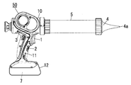
- FIG. 1 is a side view of a power tool according to an embodiment of the present invention
- FIG. 2 is a circuit diagram of the power tool.
- the electric tool of the present embodiment is a portable sealing gun (caulking gun) 50 having a main switch 1 and an output adjustment switch 2.
- the motor 3 that is a drive source of the tool is accommodated in the cylindrical main body 10.
- a handle portion 11 extending from the main body portion 10 to the outside in the radial direction (the lower side in FIG. 1) includes a main switch 1 including a trigger switch and an output adjustment switch 2 including a speed adjustment dial.
- the main switch 1 is a trigger type switch.
- the main switch 1 is configured to turn on the power supply to the motor 3 by a pull-in operation and turn off the power supply to the motor 3 when the pull-in is released.
- the main switch 1 may be a switch other than the trigger type, such as a button type or a slide type.
- the main body 10 is equipped with a cylindrical cylinder 5 having a nozzle 4 at the tip.
- a rod-shaped rod (not shown) is accommodated in the cylinder 5, and a substantially disc-shaped pressing member (not shown) that is in sliding contact with the inner peripheral surface of the cylinder 5 is fixed to the tip of the rod. ing.
- the rod is slid in the axial direction by the power of the motor 3 in the main body 10, and the sealing agent in the cylinder 5 is pushed out from the discharge hole 4 a at the tip of the nozzle 4 by a pressing member at the tip of the rod.
- the battery pack 12 is detachably attached to the tip of the handle portion 11 (the lower end in FIG. 1).
- a secondary battery 7 which is a power supply unit of the sealing gun 50 is accommodated.
- the secondary battery 7 supplies power to the motor 3 and the control means 6 of the sealing gun 50.
- the control means 6 controls the rotation of the motor 3 based on inputs from the main switch 1 and the output adjustment switch 2.
- a switch means 8 composed of a FET switching element and a current detection means 9 composed of a current detection resistor, It is provided in series with the motor 3.
- the control means 6 controls the power supply to the motor 3 via the switch means 8 and detects the current value flowing through the motor 3 based on the voltage across the current detection means 9.
- the control means 6 drives the switch means 8 by PWM control that changes the on-duty according to the voltage value determined based on the rotational position of the output adjustment switch 2. Thereby, the rotation speed of the motor 3 is controlled.
- control means 6 detects the current value of the motor 3 using the current detection means 9, and when the detection result (detection current) exceeds a predetermined threshold, the switch means 8 is turned off, Even if the main switch 1 is pulled in, the motor 3 is forcibly stopped.
- the threshold here changes according to the dial rotation position of the output adjustment switch 2 (that is, the set value of the motor output).
- the control means 6 may have a threshold value table in which the output setting value of the motor 3 set by the output adjustment switch 2 is associated with the threshold value for forcibly stopping the motor 3 (threshold value of the detected current).
- control means 6 sets a threshold value corresponding to the dial rotation position (the motor output setting value) of the output adjustment switch 2 with reference to the threshold value table.
- the threshold for forcibly stopping the motor 3 may be constant regardless of the output set value of the motor 3.
- One means is a means for releasing the pulling of the main switch 1. If the main switch 1 is turned off while the motor 3 is in a forced stop state, the control means 6 detects this by a signal change and quickly releases the forced stop state of the motor 3. Thereafter, when the main switch 1 is pulled in, the motor 3 starts to rotate again when the pull-in amount exceeds a certain amount (when the main switch 1 is turned on).
- Another means is a means for operating the output adjustment switch 2. If the output adjustment switch 2 is rotated over a predetermined amount while the motor 3 is in a forced stop state, the control means 6 detects this by a signal change and releases the forced stop state of the motor 3. At this time, since the main switch 1 remains in the retracted state (ON state), the rotation of the motor 3 is resumed promptly.
- the means for using the output adjustment switch 2 does not return from the forced stop state, but the means for using the main switch 1 is used. It is configured to be restored only.
- the control means 6 of the present embodiment has a first release condition and a second release condition as release conditions for releasing the forced stop state of the motor 3, and can satisfy one of the release conditions.
- the switch means 8 is released (the control means 6 continues to maintain the forced stop state if none of the release conditions is satisfied after the transition to the forced stop state).
- This first release condition is a condition that the main switch 1 is retracted when in the forced stop state.
- the second release condition is a condition that the output adjustment switch 2 is operated beyond a predetermined amount within a predetermined time after the forced stop state.
- the detection current threshold is set to a threshold value before the motor 3 is forcibly stopped for a certain period after the return. It is configured to change to a new threshold value (second threshold value) larger than the first threshold value).
- the control means 6 has a first threshold value and a second threshold value higher than the first threshold value. At the initial time point, the control means 6 sets a first threshold value as a detection current threshold value for forcibly stopping the motor 3. The control means 6 forcibly stops the motor 3 when the current detected via the current detection means 9 exceeds the first threshold. And the control means 6 is comprised so that the threshold value of a detection electric current may be changed from a 1st threshold value to a 2nd threshold value, when the 2nd cancellation
- the control means 6 may be configured to return the detection current threshold to the first threshold when the main switch 1 is turned off after changing the detection current threshold to the second threshold.
- control unit 6 may be configured to return the detection current threshold value to the first threshold value after a predetermined time has elapsed after the main switch 1 is turned off after the detection current threshold value is changed to the second threshold value. (That is, if the main switch 1 is turned on again after a predetermined time has elapsed after the main switch 1 is turned off, the control means 6 may maintain the threshold value of the detected current as the second threshold value. Good).
- FIG. 3 shows an example of each signal and operation in the sealing gun 50.
- the current flowing through the motor 3 reaches the overload protection threshold, and the control means 6 remains in the state where the main switch 1 is pulled in (the main switch 1 is on).
- the motor 3 is forcibly stopped.
- the pulling of the main switch 1 is released, and the forcible stop of the motor 3 is released by the control means 6 detecting this, and the timing at which the main switch 1 is drawn at the point C in the figure ( At the timing when the main switch 1 is turned on, the motor 3 starts to rotate again.
- the current flowing through the motor 3 reaches the threshold again, and the motor 3 is forcibly stopped by the control means 6 while the main switch 1 is pulled in (the main switch 1 is on).
- the output adjustment switch (speed adjustment dial) 2 is operated while the main switch 1 is retracted, and the forced stop of the motor 3 is released by the control means 6 that detects this, and the motor 3 rotates quickly. Has resumed. With the release of the forced stop here, the current threshold is changed to another higher threshold (second threshold).
- the electric tool flows through the motor 3 that is a drive source of the tool, the main switch 1 that turns on / off the power supply to the motor 3, and the motor 3.
- Current detection means 9 for detecting the current value
- output adjustment switch 2 for adjusting the rotation output of the motor 3, and control means for forcibly stopping the motor 3 when the detection result of the current detection means 9 exceeds a predetermined threshold value 6.
- the control means 6 has a forced stop state, which is a state set to forcibly stop the motor 3.
- the control means 6 has a first release condition that the main switch 1 is turned off when in the forced stop state and a second release condition that the output adjustment switch 2 is operated when in the forced stop state. Have.
- the control means 6 releases the forced stop state when the first or second release condition is satisfied.
- the main switch 1 is configured to turn on the power supply to the motor 3 by a pull-in operation.
- the first release condition is a condition that the main switch 1 is retracted when in the forced stop state.
- the motor 3 when the motor 3 is forcibly stopped, the user returns from the forced stop state by opening the main switch 1 or operates the output adjustment switch 2 while the main switch 1 is pulled in. Whether to return from the forced stop state can be selected according to the situation.
- the forced stop for overcurrent protection is performed relatively frequently, such as the operation with the sealing gun 50
- the main switch 1 can be continued while the operation is continued, thereby greatly improving the work efficiency. To improve. That is, every time the motor 3 is forcibly stopped, the work of temporarily turning off the main switch 1 and turning on the main switch 1 again becomes unnecessary, and the work efficiency is improved.
- the second release condition is a condition that the output adjustment switch 2 is operated exceeding a predetermined amount when in the forced stop state.
- the second release condition is a condition that the output adjustment switch 2 is operated within a predetermined time after the forced stop state.
- the return means can be only the main switch 1. Therefore, a situation in which the output adjustment switch 2 is unexpectedly operated to return from the forced stop state is suppressed.
- control means 6 changes a threshold value to another threshold value (2nd threshold value) higher than this (1st threshold value). It is configured.
Landscapes
- Engineering & Computer Science (AREA)
- Power Engineering (AREA)
- Mechanical Engineering (AREA)
- Portable Power Tools In General (AREA)
- Control Of Presses (AREA)
- Control Of Direct Current Motors (AREA)
Abstract
電動工具のモータ電流が閾値を越えたときには強制停止させて安全性を確保し、且つ、このために作業性が低下することは抑える。本発明の電動工具は、モータ3と、モータ3への電力供給をオンオフするメインスイッチ1と、モータ3の電流値を検出する電流検出手段と、モータ3の回転出力を調整する出力調整スイッチ2と、電流検出手段での検出結果が所定の閾値を超えた場合にモータ3を強制停止させる制御手段とを具備する。制御手段は、強制停止状態にあるときにメインスイッチ1がオフされるか、或いは、強制停止状態にあるときに出力調整スイッチ2が動作されることで、強制停止状態を解除する。
Description
本発明は、電流が閾値を越えたときにモータを強制停止させる電動工具に関する。
電動工具では、モータに過電流が流れることを防止するため、電流が閾値を超えたときにこれを検知してモータを強制停止させることが、従来行われている。さらに、日本国特許公開平1-311887号公報に記載の電動工具においては、モータが強制停止されたとき、使用者が操作スイッチを引き込んでいる間はこの強制停止を継続させ、操作スイッチの引き込みを解除した段階でこの強制停止を解除するように構成されている。
前記した従来の電動工具では、モータの強制停止を解除するために、いったん操作スイッチから指を離してその引き込みを解除する必要がある。そのため、モータに過電流が生じやすい作業を行うような場合には、モータが強制停止される度にいったん操作スイッチから指を離し、再び操作スイッチを引き込むという作業が要求され、作業性の低下を招く原因となっていた。
本発明は前記問題点に鑑みて発明したものであって、電流が閾値を越えたときにはモータを強制停止させて安全性を確保し、且つ、このために作業性が低下することを抑えることのできる電動工具を提供することを、課題とする。
前記課題を解決するために本発明の電動工具を、工具の駆動源であるモータと、前記モータへの電力供給をオンオフするメインスイッチと、前記モータに流れる電流値を検出する電流検出手段と、前記モータの回転出力を調整する出力調整スイッチと、前記電流検出手段での検出結果が所定の閾値を超えた場合に前記モータを強制停止させる制御手段とを具備し、前記制御手段は、前記モータを強制停止させるよう設定された状態である強制停止状態を有し、前記制御手段は、前記強制停止状態にあるときに前記メインスイッチがオフされるという第一の解除条件と、前記強制停止状態にあるときに前記出力調整スイッチが動作されるという第二の解除条件とを有し、前記制御手段は、前記第一又は第二の解除条件を満たしたときに前記強制停止状態を解除するものとする。
言い換えれば、本発明の電動工具は、工具の駆動源であるモータと、前記モータへの電力供給をオンオフするメインスイッチと、前記モータに流れる電流値を検出する電流検出手段と、前記モータの回転出力を調整する出力調整スイッチと、前記電流検出手段での検出結果が所定の閾値を超えた場合に前記モータを強制停止させる制御手段とを具備し、前記制御手段は、前記モータを強制停止させているときに前記メインスイッチがオフされるという第一の解除条件と、前記モータを強制停止させているときに前記出力調整スイッチが動作されるという第二の解除条件とを有し、前記制御手段は、前記第一又は第二の解除条件を満たしたときに前記モータの強制停止を解除するよう構成されている。
前記メインスイッチは、引き込み操作により前記モータへの電力供給をオンするよう構成され、前記第一の解除条件は、前記強制停止状態にあるときに前記メインスイッチの引き込みが開放されるという条件であることが好ましい。
言い換えれば、前記メインスイッチは、引き込み操作により前記モータへの電力供給をオンするよう構成され、前記第一の解除条件は、前記制御手段が前記モータを強制停止させているときに前記メインスイッチの引き込みが開放されるという条件であることが好ましい。
前記第二の解除条件は、前記強制停止状態にあるときに前記出力調整スイッチが所定量を超えて動作されるという条件であることが好ましい。
言い換えれば、前記第二の解除条件は、前記制御手段が前記モータを強制停止させているときに前記出力調整スイッチが所定量を超えて動作されるという条件であることが好ましい。
また、前記第二の解除条件は、前記強制停止状態となってから所定時間以内に前記出力調整スイッチが動作されるという条件であることが好ましい。
言い換えれば、前記第二の解除条件は、前記制御手段が前記モータを強制停止させた時点から所定時間以内に前記出力調整スイッチが動作されるという条件であることが好ましい。
前記制御手段は、前記第二の解除条件を満たして前記強制停止状態を解除した後は、前記閾値をこれよりも高い別の閾値に変更するよう構成されていることが好ましい。
言い換えれば、前記制御手段は、前記第二の解除条件を満たして前記モータの強制停止を解除した後は、前記閾値をこれよりも高い別の閾値に変更するよう構成されていることが好ましい。
また、前記モータの回転を制御するためのスイッチ手段をさらに備え、前記制御手段は、前記出力調整スイッチで設定された回転出力の値に基づいて前記スイッチ手段を制御するよう構成され、前記制御手段は、前記電流検出手段で検出された電流値が所定の閾値を超えた場合に、前記スイッチ手段をオフさせることで、前記モータを強制停止させることが好ましい。
本発明は、電流が閾値を越えたときにはモータを強制停止させて安全性を確保し、且つ、このために作業性が低下することは抑えることができるという効果を奏する。
本発明を、添付図面に示す実施形態に基づいて説明する。図1は、本発明の一実施形態の電動工具の側面図であり、図2はこの電動工具の回路図である。
本実施形態の電動工具は、メインスイッチ1と出力調整スイッチ2を備えた可搬式のシーリングガン(コーキングガン)50である。このシーリングガン50では、工具の駆動源であるモータ3を筒型の本体部10内に収容している。この本体部10から径方向外側(図1の下側)にむけて延設されるハンドル部11に、トリガスイッチから成るメインスイッチ1と、速度調整ダイヤルから成る出力調整スイッチ2を備えている。本実施形態の電動工具では、メインスイッチ1はトリガ式のスイッチである。メインスイッチ1は、引き込み操作によりモータ3への電力供給をオンし、引き込みが開放されたときにモータ3への電力供給をオフするよう、構成されている。なおメインスイッチ1は、ボタン式やスライド式など、トリガ式以外のスイッチであってもよい。
本体部10には、先端にノズル4を有する円筒状のシリンダ5を装着している。このシリンダ5内には棒状のロッド(図示せず)が収容されており、ロッドの先端には、シリンダ5の内周面に摺接する略円板状の押圧部材(図示せず)を固定させている。ロッドは、本体部10内のモータ3の動力によって軸方向にスライド移動され、ロッド先端の押圧部材によって、シリンダ5内のシーリング剤をノズル4先端の吐出孔4aから押し出していく。
ハンドル部11の先端(図1の下側の端部)には、電池パック12が着脱自在に装着される。この電池パック12内には、シーリングガン50の電源部である二次電池7が収容されている。二次電池7は、シーリングガン50のモータ3や制御手段6に対して、電力を供給する。この制御手段6は、メインスイッチ1や出力調整スイッチ2からの入力に基づいてモータ3の回転を制御する。
図2の回路図に示すように、二次電池7からモータ3に電力を供給する回路中には、FETのスイッチング素子から成るスイッチ手段8と、電流検出抵抗から成る電流検出手段9とを、モータ3と直列に備えている。制御手段6は、スイッチ手段8を介してモータ3への電力供給を制御し、また、電流検出手段9の両端電圧に基づいてモータ3に流れる電流値を検出する。
上記構成を具備するシーリングガン50において、一定量を超えてメインスイッチ1を引き込み操作する(つまり、メインスイッチ1をオンする)と、モータ3への電力供給がオンになる。このメインスイッチ1の引き込みを開放する(つまり、メインスイッチ1をオフする)と、モータ3への電力供給はオフになる。制御手段6は、出力調整スイッチ2の回転位置に基づいて決定される電圧値に応じてオンデューティを変化させるPWM制御によって、スイッチ手段8を駆動させる。これにより、モータ3の回転数が制御される。
また、制御手段6は、電流検出手段9を用いてモータ3の電流値を検出し、この検出結果(検出電流)が所定の閾値を越えた場合に、スイッチ手段8をオフにすることで、メインスイッチ1が引き込まれた状態であってもモータ3を強制停止させる。ここでの閾値は、出力調整スイッチ2のダイヤル回転位置(即ち、モータ出力の設定値)に応じて変化する。例えば、制御手段6は、出力調整スイッチ2で設定されるモータ3の出力設定値とモータ3を強制停止させる閾値(検出電流の閾値)とを対応付けた、閾値テーブルを有してもよい。この場合、制御手段6は、閾値テーブルを参照して、出力調整スイッチ2のダイヤル回転位置(モータ出力の設定値)に対応した閾値を設定する。なお、モータ3を強制停止させる閾値は、モータ3の出力設定値によらず一定であってもよい。
本実施形態のシーリングガン50では、モータ3の強制停止状態に移行した後、この強制停止状態を解除して作業を再開するには、2通りの手段が用いられる。
1つの手段は、メインスイッチ1の引き込みを開放する手段である。モータ3の強制停止状態にあるときにメインスイッチ1がオフになると、制御手段6は信号変化によってこれを検知し、モータ3の強制停止状態を速やかに解除する。その後メインスイッチ1を引き込むと、その引き込み量が一定量を超えた時点(メインスイッチ1がオンになった時点)からモータ3は再び回転を始める。
もう1つの手段は、出力調整スイッチ2を動作させる手段である。モータ3の強制停止状態にあるときに出力調整スイッチ2が所定量を超えて回転動作されると、制御手段6は信号変化によってこれを検知し、モータ3の強制停止状態を解除する。このとき、メインスイッチ1は引き込み状態(オン状態)のままにあるので、モータ3の回転は速やかに再開される。
なお、本実施形態では、モータ3が強制停止されてから所定時間を経過した後は、この出力調整スイッチ2を用いた手段によっては強制停止状態から復帰されず、メインスイッチ1を用いた手段によってのみ復帰されるように構成されている。
言い換えれば、本実施形態の制御手段6は、モータ3の強制停止状態を解除するための解除条件として、第一の解除条件と第二の解除条件を有し、いずれか一方の解除条件を満たせばスイッチ手段8のオフを解除する(制御手段6は、強制停止状態に移行した後何れの解除条件も満たされなければ、強制停止状態を維持し続ける)。この第一の解除条件は、強制停止状態にあるときにメインスイッチ1の引き込みが開放される、という条件である。そして、第二の解除条件は、強制停止状態となってから所定時間以内に出力調整スイッチ2が所定量を超えて動作される、という条件である。制御手段6は、(信号検知などによって)第一の解除条件または第二の解除条件が満たされたことを検知したときに、スイッチ手段8のオフを解除して、強制停止状態を解除する。
更に、この制御手段6においては、出力調整スイッチ2を動作させて強制停止状態から復帰した後は、復帰後の一定期間の間、検出電流の閾値を、モータ3を強制停止させる前の閾値(第一の閾値)よりも大きな新たな閾値(第二の閾値)に変更するように構成されている。
すなわち制御手段6は、第一の閾値とこれよりも高い第二の閾値を有する。初期時点では、制御手段6は、モータ3を強制停止させるための検出電流の閾値として第一の閾値を設定する。制御手段6は、電流検出手段9を介して検出した電流が第一の閾値を超えた場合に、モータ3を強制停止させる。そして制御手段6は、第二の解除条件を満たして強制停止状態を解除した場合には、検出電流の閾値を、第一の閾値から第二の閾値に変更するよう構成されている。
なお、制御手段6は、検出電流の閾値を第二の閾値に変更した後は、メインスイッチ1がオフされたときに、検出電流の閾値を第一の閾値に戻すよう構成されてもよい。
或いは制御手段6は、検出電流の閾値を第二の閾値に変更した後は、メインスイッチ1がオフされてから所定時間経過後に、検出電流の閾値を第一の閾値に戻すよう構成されてもよい(すなわち、制御手段6は、メインスイッチ1がオフされた後、所定時間経過前に再度メインスイッチ1がオンされた場合には、検出電流の閾値を第二の閾値のまま維持してもよい)。
図3は、このシーリングガン50での各信号と動作の一例を示している。この例の場合、図中のA点にて、モータ3を流れる電流が過負荷保護用の閾値に達し、メインスイッチ1を引き込んだ状態(メインスイッチ1がオンの状態)のまま、制御手段6によってモータ3が強制停止されている。次いで、図中B点にて、メインスイッチ1の引き込みが開放され、これを検知した制御手段6によってモータ3の強制停止は解除され、図中C点にてメインスイッチ1が引き込まれたタイミング(メインスイッチ1がオンされたタイミング)で、モータ3は再度回転を始めている。
図中D点では、モータ3を流れる電流が再び閾値に達し、メインスイッチ1を引き込んだ状態(メインスイッチ1がオンの状態)のまま、制御手段6によってモータ3が強制停止されている。次いで、図中E点では、メインスイッチ1が引き込まれたまま、出力調整スイッチ(速度調整ダイヤル)2が動作され、これを検知した制御手段6によってモータ3の強制停止が解除され、速やかに回転を再開している。そして、ここでの強制停止の解除に伴い、電流の閾値は更に高い別の閾値(第二の閾値)に変更されている。
以上説明したように、本発明の一実施形態の電動工具(シーリングガン50)は、工具の駆動源であるモータ3と、モータ3への電力供給をオンオフするメインスイッチ1と、モータ3に流れる電流値を検出する電流検出手段9と、モータ3の回転出力を調整する出力調整スイッチ2と、電流検出手段9での検出結果が所定の閾値を超えた場合にモータ3を強制停止させる制御手段6とを具備する。制御手段6は、モータ3を強制停止させるよう設定された状態である、強制停止状態を有する。制御手段6は、強制停止状態にあるときにメインスイッチ1がオフされるという第一の解除条件と、強制停止状態にあるときに出力調整スイッチ2が動作されるという第二の解除条件とを有する。制御手段6は、第一又は第二の解除条件を満たしたときに強制停止状態を解除する。
本発明の一実施形態の電動工具では具体的には、メインスイッチ1は、引き込み操作によりモータ3への電力供給をオンするよう構成されている。そして、第一の解除条件は、強制停止状態にあるときにメインスイッチ1の引き込みが開放されるという条件である。
これにより、使用者は、モータ3が強制停止されたときに、メインスイッチ1を開放することで強制停止状態から復帰させるか、或いは、メインスイッチ1を引き込んだまま出力調整スイッチ2を動作させることで強制停止状態から復帰させるかを、状況に応じて選択することができる。特に、シーリングガン50での作業のような、過電流保護のための強制停止が比較的頻繁に行われる作業の場合には、メインスイッチ1は引き込んだままで作業を継続できることにより、作業能率が大幅に向上する。すなわち、モータ3が強制停止される度にメインスイッチ1を一旦オフにして再びメインスイッチ1をオンにするという作業が不要となり、作業能率が向上する。
また本実施形態では、前記第二の解除条件は、強制停止状態にあるときに出力調整スイッチ2が所定量を超えて動作される、という条件である。
これによると、強制停止状態を解除するためには、所定量を超えて出力調整スイッチ2を動作させる必要があるので、使用者が意図しないタイミングで強制停止状態から復帰するといった事態が抑えられる。例えば、出力調整スイッチ2が、壁などに接触することによって使用者が意図しないタイミングで動かされたとしても、強制停止状態が解除されにくくなる。従って、工具の安全性や利便性を向上させることができる。
また本実施形態では、前記第二の解除条件は、強制停止状態となってから所定時間以内に出力調整スイッチ2が動作される、という条件である。
これによると、連続作業を行わない場合には、復帰手段をメインスイッチ1のみにすることができる。したがって、不意に出力調整スイッチ2を動作させて強制停止状態から復帰するという事態が抑制される。
また、制御手段6は、前記第二の解除条件を満たして強制停止状態を解除した後は、閾値をこれ(第一の閾値)よりも高い別の閾値(第二の閾値)に変更するよう構成されている。
これによると、連続作業を行うような場合に、モータ3の強制停止が多発することを抑えることができ、作業効率が向上する。
以上、本発明を添付図面に示す実施形態に基づいて説明したが、本発明は前記実施形態に限定されるものではなく、本発明の意図する範囲内であれば、適宜の設計変更を行うことが可能である。
Claims (6)
- 工具の駆動源であるモータと、前記モータへの電力供給をオンオフするメインスイッチと、前記モータに流れる電流値を検出する電流検出手段と、前記モータの回転出力を調整する出力調整スイッチと、前記電流検出手段での検出結果が所定の閾値を超えた場合に前記モータを強制停止させる制御手段とを具備し、
前記制御手段は、前記モータを強制停止させるよう設定された状態である強制停止状態を有し、
前記制御手段は、前記強制停止状態にあるときに前記メインスイッチがオフされるという第一の解除条件と、前記強制停止状態にあるときに前記出力調整スイッチが動作されるという第二の解除条件とを有し、
前記制御手段は、前記第一又は第二の解除条件を満たしたときに前記強制停止状態を解除することを特徴とする電動工具。 - 前記メインスイッチは、引き込み操作により前記モータへの電力供給をオンするよう構成され、
前記第一の解除条件は、前記強制停止状態にあるときに前記メインスイッチの引き込みが開放されるという条件であることを特徴とする請求項1に記載の電動工具。 - 前記第二の解除条件は、前記強制停止状態にあるときに前記出力調整スイッチが所定量を超えて動作されるという条件であることを特徴とする請求項1又は2に記載の電動工具。
- 前記第二の解除条件は、前記強制停止状態となってから所定時間以内に前記出力調整スイッチが動作されるという条件であることを特徴とする請求項1~3のいずれか一項に記載の電動工具。
- 前記制御手段は、前記第二の解除条件を満たして前記強制停止状態を解除した後は、前記閾値をこれよりも高い別の閾値に変更するよう構成されていることを特徴とする請求項1~4のいずれか一項に記載の電動工具。
- 前記モータの回転を制御するためのスイッチ手段をさらに備え、
前記制御手段は、前記出力調整スイッチで設定された回転出力の値に基づいて前記スイッチ手段を制御するよう構成され、
前記制御手段は、前記電流検出手段で検出された電流値が所定の閾値を超えた場合に、前記スイッチ手段をオフさせることで、前記モータを強制停止させることを特徴とする請求項1に記載の電動工具。
Priority Applications (2)
| Application Number | Priority Date | Filing Date | Title |
|---|---|---|---|
| EP12760058.3A EP2689896B1 (en) | 2011-03-23 | 2012-02-17 | Electric tool |
| CN201280014528.3A CN103429394B (zh) | 2011-03-23 | 2012-02-17 | 电动工具 |
Applications Claiming Priority (2)
| Application Number | Priority Date | Filing Date | Title |
|---|---|---|---|
| JP2011063659A JP5799221B2 (ja) | 2011-03-23 | 2011-03-23 | 電動工具 |
| JP2011-063659 | 2011-03-23 |
Publications (1)
| Publication Number | Publication Date |
|---|---|
| WO2012127950A1 true WO2012127950A1 (ja) | 2012-09-27 |
Family
ID=46879113
Family Applications (1)
| Application Number | Title | Priority Date | Filing Date |
|---|---|---|---|
| PCT/JP2012/053789 Ceased WO2012127950A1 (ja) | 2011-03-23 | 2012-02-17 | 電動工具 |
Country Status (4)
| Country | Link |
|---|---|
| EP (1) | EP2689896B1 (ja) |
| JP (1) | JP5799221B2 (ja) |
| CN (1) | CN103429394B (ja) |
| WO (1) | WO2012127950A1 (ja) |
Families Citing this family (3)
| Publication number | Priority date | Publication date | Assignee | Title |
|---|---|---|---|---|
| JP6178136B2 (ja) * | 2013-07-03 | 2017-08-09 | 株式会社マキタ | 電動工具 |
| CN108459519B (zh) * | 2017-02-22 | 2021-04-06 | 苏州宝时得电动工具有限公司 | 电动扳手控制方法及装置 |
| US12445081B2 (en) | 2020-07-15 | 2025-10-14 | Koki Holdings Co., Ltd. | Working tool and drilling method |
Citations (5)
| Publication number | Priority date | Publication date | Assignee | Title |
|---|---|---|---|---|
| JPS63103623A (ja) * | 1986-10-18 | 1988-05-09 | 松下電工株式会社 | 電動機器 |
| JPH0799721A (ja) * | 1993-09-28 | 1995-04-11 | Makita Corp | 直流モータの過負荷防止回路 |
| JP2001252602A (ja) * | 2000-03-09 | 2001-09-18 | Ire:Kk | 電動工具 |
| US20070069672A1 (en) * | 2000-12-06 | 2007-03-29 | Glasgow Kevin L | Power tool and motor controller |
| WO2007067352A1 (en) * | 2005-12-09 | 2007-06-14 | Temple University - Of The Commonwealth System Of Higher Education | Mixer |
Family Cites Families (3)
| Publication number | Priority date | Publication date | Assignee | Title |
|---|---|---|---|---|
| JP5122750B2 (ja) * | 2006-02-23 | 2013-01-16 | パナソニック株式会社 | 電動工具 |
| EP2015421B1 (en) * | 2007-07-13 | 2016-03-09 | Black & Decker, Inc. | Reset mechanism for a battery pack |
| CN101714647B (zh) * | 2008-10-08 | 2012-11-28 | 株式会社牧田 | 电动工具用蓄电池匣以及电动工具 |
-
2011
- 2011-03-23 JP JP2011063659A patent/JP5799221B2/ja active Active
-
2012
- 2012-02-17 EP EP12760058.3A patent/EP2689896B1/en active Active
- 2012-02-17 CN CN201280014528.3A patent/CN103429394B/zh not_active Expired - Fee Related
- 2012-02-17 WO PCT/JP2012/053789 patent/WO2012127950A1/ja not_active Ceased
Patent Citations (5)
| Publication number | Priority date | Publication date | Assignee | Title |
|---|---|---|---|---|
| JPS63103623A (ja) * | 1986-10-18 | 1988-05-09 | 松下電工株式会社 | 電動機器 |
| JPH0799721A (ja) * | 1993-09-28 | 1995-04-11 | Makita Corp | 直流モータの過負荷防止回路 |
| JP2001252602A (ja) * | 2000-03-09 | 2001-09-18 | Ire:Kk | 電動工具 |
| US20070069672A1 (en) * | 2000-12-06 | 2007-03-29 | Glasgow Kevin L | Power tool and motor controller |
| WO2007067352A1 (en) * | 2005-12-09 | 2007-06-14 | Temple University - Of The Commonwealth System Of Higher Education | Mixer |
Also Published As
| Publication number | Publication date |
|---|---|
| JP2012196746A (ja) | 2012-10-18 |
| EP2689896B1 (en) | 2021-03-31 |
| CN103429394B (zh) | 2015-05-13 |
| EP2689896A1 (en) | 2014-01-29 |
| EP2689896A4 (en) | 2015-10-14 |
| JP5799221B2 (ja) | 2015-10-21 |
| CN103429394A (zh) | 2013-12-04 |
Similar Documents
| Publication | Publication Date | Title |
|---|---|---|
| EP2329922B1 (en) | Rotary tool having a feedback control function | |
| JP6901898B2 (ja) | 回転打撃工具 | |
| JP2014050923A (ja) | 電動工具 | |
| JP2017042839A (ja) | 回転打撃工具 | |
| US11247323B2 (en) | Electric working machine and method of controlling rotational state of motor of electric working machine | |
| US20190047131A1 (en) | Electric working machine and method of controlling rotational state of motor of electric working machine | |
| JP2015062981A (ja) | 電動工具 | |
| WO2007112303A3 (en) | Power tool with improved start actuator | |
| US7750587B2 (en) | Method of controlling a motor of a battery-operated power tool | |
| WO2012127950A1 (ja) | 電動工具 | |
| WO2013136683A1 (ja) | 電動工具及び電動工具の制御装置 | |
| JP5834240B2 (ja) | 電動工具 | |
| JP5963136B2 (ja) | 電動工具 | |
| WO2013024090A3 (de) | Betrieb eines leuchtmittels mit autonomem energiespeicher | |
| WO2009006172A3 (en) | Electronic motor controller and method for controlling a motor | |
| JP2015009284A (ja) | 電動工具 | |
| JP2013066948A (ja) | 電動工具 | |
| JP2005006384A (ja) | 電動工具用スイッチおよび同スイッチを用いた電動工具 | |
| EP2724822B1 (en) | Power tool | |
| JP2014054708A (ja) | 電動工具 | |
| JP2012171047A (ja) | 電動工具 | |
| JP2009268244A5 (ja) | ||
| JP5938628B2 (ja) | 電動工具 | |
| JP2013066947A (ja) | 電動工具 | |
| JP5997497B2 (ja) | 電動アクチュエータ |
Legal Events
| Date | Code | Title | Description |
|---|---|---|---|
| 121 | Ep: the epo has been informed by wipo that ep was designated in this application |
Ref document number: 12760058 Country of ref document: EP Kind code of ref document: A1 |
|
| NENP | Non-entry into the national phase |
Ref country code: DE |