WO2012127950A1 - Outil électrique - Google Patents
Outil électrique Download PDFInfo
- Publication number
- WO2012127950A1 WO2012127950A1 PCT/JP2012/053789 JP2012053789W WO2012127950A1 WO 2012127950 A1 WO2012127950 A1 WO 2012127950A1 JP 2012053789 W JP2012053789 W JP 2012053789W WO 2012127950 A1 WO2012127950 A1 WO 2012127950A1
- Authority
- WO
- WIPO (PCT)
- Prior art keywords
- motor
- forced stop
- switch
- stop state
- control means
- Prior art date
- Legal status (The legal status is an assumption and is not a legal conclusion. Google has not performed a legal analysis and makes no representation as to the accuracy of the status listed.)
- Ceased
Links
Images


Classifications
-
- B—PERFORMING OPERATIONS; TRANSPORTING
- B25—HAND TOOLS; PORTABLE POWER-DRIVEN TOOLS; MANIPULATORS
- B25F—COMBINATION OR MULTI-PURPOSE TOOLS NOT OTHERWISE PROVIDED FOR; DETAILS OR COMPONENTS OF PORTABLE POWER-DRIVEN TOOLS NOT PARTICULARLY RELATED TO THE OPERATIONS PERFORMED AND NOT OTHERWISE PROVIDED FOR
- B25F5/00—Details or components of portable power-driven tools not particularly related to the operations performed and not otherwise provided for
-
- B—PERFORMING OPERATIONS; TRANSPORTING
- B05—SPRAYING OR ATOMISING IN GENERAL; APPLYING FLUENT MATERIALS TO SURFACES, IN GENERAL
- B05C—APPARATUS FOR APPLYING FLUENT MATERIALS TO SURFACES, IN GENERAL
- B05C17/00—Hand tools or apparatus using hand held tools, for applying liquids or other fluent materials to, for spreading applied liquids or other fluent materials on, or for partially removing applied liquids or other fluent materials from, surfaces
- B05C17/005—Hand tools or apparatus using hand held tools, for applying liquids or other fluent materials to, for spreading applied liquids or other fluent materials on, or for partially removing applied liquids or other fluent materials from, surfaces for discharging material from a reservoir or container located in or on the hand tool through an outlet orifice by pressure without using surface contacting members like pads or brushes
- B05C17/01—Hand tools or apparatus using hand held tools, for applying liquids or other fluent materials to, for spreading applied liquids or other fluent materials on, or for partially removing applied liquids or other fluent materials from, surfaces for discharging material from a reservoir or container located in or on the hand tool through an outlet orifice by pressure without using surface contacting members like pads or brushes with manually mechanically or electrically actuated piston or the like
- B05C17/0103—Hand tools or apparatus using hand held tools, for applying liquids or other fluent materials to, for spreading applied liquids or other fluent materials on, or for partially removing applied liquids or other fluent materials from, surfaces for discharging material from a reservoir or container located in or on the hand tool through an outlet orifice by pressure without using surface contacting members like pads or brushes with manually mechanically or electrically actuated piston or the like with electrically actuated piston or the like
-
- H—ELECTRICITY
- H02—GENERATION; CONVERSION OR DISTRIBUTION OF ELECTRIC POWER
- H02H—EMERGENCY PROTECTIVE CIRCUIT ARRANGEMENTS
- H02H7/00—Emergency protective circuit arrangements specially adapted for specific types of electric machines or apparatus or for sectionalised protection of cable or line systems, and effecting automatic switching in the event of an undesired change from normal working conditions
- H02H7/08—Emergency protective circuit arrangements specially adapted for specific types of electric machines or apparatus or for sectionalised protection of cable or line systems, and effecting automatic switching in the event of an undesired change from normal working conditions for dynamo-electric motors
- H02H7/085—Emergency protective circuit arrangements specially adapted for specific types of electric machines or apparatus or for sectionalised protection of cable or line systems, and effecting automatic switching in the event of an undesired change from normal working conditions for dynamo-electric motors against excessive load
-
- H—ELECTRICITY
- H02—GENERATION; CONVERSION OR DISTRIBUTION OF ELECTRIC POWER
- H02J—ELECTRIC POWER NETWORKS; CIRCUIT ARRANGEMENTS OR SYSTEMS FOR SUPPLYING OR DISTRIBUTING ELECTRIC POWER; SYSTEMS FOR STORING ELECTRIC ENERGY
- H02J7/00—Circuit arrangements for charging or discharging batteries or for supplying loads from batteries
- H02J7/855—Circuit arrangements for charging or discharging batteries or for supplying loads from batteries with circuits adapted for supplying loads from the battery
-
- H—ELECTRICITY
- H02—GENERATION; CONVERSION OR DISTRIBUTION OF ELECTRIC POWER
- H02J—ELECTRIC POWER NETWORKS; CIRCUIT ARRANGEMENTS OR SYSTEMS FOR SUPPLYING OR DISTRIBUTING ELECTRIC POWER; SYSTEMS FOR STORING ELECTRIC ENERGY
- H02J7/00—Circuit arrangements for charging or discharging batteries or for supplying loads from batteries
- H02J7/90—Regulation of charging or discharging current or voltage
- H02J7/94—Regulation of charging or discharging current or voltage in response to battery current
-
- H—ELECTRICITY
- H01—ELECTRIC ELEMENTS
- H01M—PROCESSES OR MEANS, e.g. BATTERIES, FOR THE DIRECT CONVERSION OF CHEMICAL ENERGY INTO ELECTRICAL ENERGY
- H01M10/00—Secondary cells; Manufacture thereof
- H01M10/42—Methods or arrangements for servicing or maintenance of secondary cells or secondary half-cells
- H01M10/425—Structural combination with electronic components, e.g. electronic circuits integrated to the outside of the casing
- H01M10/4257—Smart batteries, e.g. electronic circuits inside the housing of the cells or batteries
-
- H—ELECTRICITY
- H02—GENERATION; CONVERSION OR DISTRIBUTION OF ELECTRIC POWER
- H02J—ELECTRIC POWER NETWORKS; CIRCUIT ARRANGEMENTS OR SYSTEMS FOR SUPPLYING OR DISTRIBUTING ELECTRIC POWER; SYSTEMS FOR STORING ELECTRIC ENERGY
- H02J7/00—Circuit arrangements for charging or discharging batteries or for supplying loads from batteries
- H02J7/60—Circuit arrangements for charging or discharging batteries or for supplying loads from batteries including safety or protection arrangements
- H02J7/62—Circuit arrangements for charging or discharging batteries or for supplying loads from batteries including safety or protection arrangements against overcurrent
-
- Y—GENERAL TAGGING OF NEW TECHNOLOGICAL DEVELOPMENTS; GENERAL TAGGING OF CROSS-SECTIONAL TECHNOLOGIES SPANNING OVER SEVERAL SECTIONS OF THE IPC; TECHNICAL SUBJECTS COVERED BY FORMER USPC CROSS-REFERENCE ART COLLECTIONS [XRACs] AND DIGESTS
- Y02—TECHNOLOGIES OR APPLICATIONS FOR MITIGATION OR ADAPTATION AGAINST CLIMATE CHANGE
- Y02E—REDUCTION OF GREENHOUSE GAS [GHG] EMISSIONS, RELATED TO ENERGY GENERATION, TRANSMISSION OR DISTRIBUTION
- Y02E60/00—Enabling technologies; Technologies with a potential or indirect contribution to GHG emissions mitigation
- Y02E60/10—Energy storage using batteries
Definitions
- the present invention relates to an electric tool that forcibly stops a motor when a current exceeds a threshold value.
- the present invention has been invented in view of the above problems, and when the current exceeds a threshold value, the motor is forcibly stopped to ensure safety, and for this reason, it is possible to suppress deterioration in workability. It is an object to provide a power tool that can be used.
- the electric tool of the present invention includes a motor that is a driving source of the tool, a main switch that turns on and off power supply to the motor, and a current detection unit that detects a current value flowing through the motor, An output adjustment switch that adjusts the rotation output of the motor; and a control unit that forcibly stops the motor when a detection result of the current detection unit exceeds a predetermined threshold value.
- a forced stop state that is set to forcibly stop, and the control means includes a first release condition that the main switch is turned off when in the forced stop state, and the forced stop state.
- a second release condition that the output adjustment switch is operated when the control means satisfies the first or second release condition. It shall be released in the stopped state.
- the electric tool of the present invention includes a motor that is a drive source of the tool, a main switch that turns on and off power supply to the motor, current detection means that detects a current value flowing through the motor, and rotation of the motor.
- An output adjustment switch for adjusting the output; and a control unit for forcibly stopping the motor when a detection result of the current detection unit exceeds a predetermined threshold, the control unit forcibly stopping the motor.
- the means is configured to release the forced stop of the motor when the first or second release condition is satisfied.
- the main switch is configured to turn on the power supply to the motor by a pull-in operation, and the first release condition is a condition that the pull-in of the main switch is released when in the forced stop state. It is preferable.
- the main switch is configured to turn on the power supply to the motor by a pull-in operation
- the first release condition is that the main switch of the main switch is stopped when the control means forcibly stops the motor.
- the condition is that the pull-in is released.
- the second release condition is a condition that the output adjustment switch is operated exceeding a predetermined amount when in the forced stop state.
- the second release condition is preferably a condition that the output adjustment switch is operated beyond a predetermined amount when the control means forcibly stops the motor.
- the second release condition is a condition that the output adjustment switch is operated within a predetermined time after the forced stop state.
- the second release condition is preferably a condition that the output adjustment switch is operated within a predetermined time from the time when the control means forcibly stops the motor.
- control unit is configured to change the threshold value to another threshold value higher than the threshold value after the second release condition is satisfied and the forced stop state is released.
- control unit is configured to change the threshold value to another threshold value higher than the threshold value after the second release condition is satisfied and the forced stop of the motor is released.
- the control means further comprises switch means for controlling the rotation of the motor, and the control means is configured to control the switch means based on the value of the rotation output set by the output adjustment switch, and the control means Preferably, the motor is forcibly stopped by turning off the switch means when the current value detected by the current detection means exceeds a predetermined threshold value.
- the present invention has an effect that when the current exceeds a threshold value, the motor is forcibly stopped to ensure safety, and the deterioration of workability due to this can be suppressed.
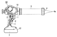
- FIG. 1 is a side view of a power tool according to an embodiment of the present invention
- FIG. 2 is a circuit diagram of the power tool.
- the electric tool of the present embodiment is a portable sealing gun (caulking gun) 50 having a main switch 1 and an output adjustment switch 2.
- the motor 3 that is a drive source of the tool is accommodated in the cylindrical main body 10.
- a handle portion 11 extending from the main body portion 10 to the outside in the radial direction (the lower side in FIG. 1) includes a main switch 1 including a trigger switch and an output adjustment switch 2 including a speed adjustment dial.
- the main switch 1 is a trigger type switch.
- the main switch 1 is configured to turn on the power supply to the motor 3 by a pull-in operation and turn off the power supply to the motor 3 when the pull-in is released.
- the main switch 1 may be a switch other than the trigger type, such as a button type or a slide type.
- the main body 10 is equipped with a cylindrical cylinder 5 having a nozzle 4 at the tip.
- a rod-shaped rod (not shown) is accommodated in the cylinder 5, and a substantially disc-shaped pressing member (not shown) that is in sliding contact with the inner peripheral surface of the cylinder 5 is fixed to the tip of the rod. ing.
- the rod is slid in the axial direction by the power of the motor 3 in the main body 10, and the sealing agent in the cylinder 5 is pushed out from the discharge hole 4 a at the tip of the nozzle 4 by a pressing member at the tip of the rod.
- the battery pack 12 is detachably attached to the tip of the handle portion 11 (the lower end in FIG. 1).
- a secondary battery 7 which is a power supply unit of the sealing gun 50 is accommodated.
- the secondary battery 7 supplies power to the motor 3 and the control means 6 of the sealing gun 50.
- the control means 6 controls the rotation of the motor 3 based on inputs from the main switch 1 and the output adjustment switch 2.
- a switch means 8 composed of a FET switching element and a current detection means 9 composed of a current detection resistor, It is provided in series with the motor 3.
- the control means 6 controls the power supply to the motor 3 via the switch means 8 and detects the current value flowing through the motor 3 based on the voltage across the current detection means 9.
- the control means 6 drives the switch means 8 by PWM control that changes the on-duty according to the voltage value determined based on the rotational position of the output adjustment switch 2. Thereby, the rotation speed of the motor 3 is controlled.
- control means 6 detects the current value of the motor 3 using the current detection means 9, and when the detection result (detection current) exceeds a predetermined threshold, the switch means 8 is turned off, Even if the main switch 1 is pulled in, the motor 3 is forcibly stopped.
- the threshold here changes according to the dial rotation position of the output adjustment switch 2 (that is, the set value of the motor output).
- the control means 6 may have a threshold value table in which the output setting value of the motor 3 set by the output adjustment switch 2 is associated with the threshold value for forcibly stopping the motor 3 (threshold value of the detected current).
- control means 6 sets a threshold value corresponding to the dial rotation position (the motor output setting value) of the output adjustment switch 2 with reference to the threshold value table.
- the threshold for forcibly stopping the motor 3 may be constant regardless of the output set value of the motor 3.
- One means is a means for releasing the pulling of the main switch 1. If the main switch 1 is turned off while the motor 3 is in a forced stop state, the control means 6 detects this by a signal change and quickly releases the forced stop state of the motor 3. Thereafter, when the main switch 1 is pulled in, the motor 3 starts to rotate again when the pull-in amount exceeds a certain amount (when the main switch 1 is turned on).
- Another means is a means for operating the output adjustment switch 2. If the output adjustment switch 2 is rotated over a predetermined amount while the motor 3 is in a forced stop state, the control means 6 detects this by a signal change and releases the forced stop state of the motor 3. At this time, since the main switch 1 remains in the retracted state (ON state), the rotation of the motor 3 is resumed promptly.
- the means for using the output adjustment switch 2 does not return from the forced stop state, but the means for using the main switch 1 is used. It is configured to be restored only.
- the control means 6 of the present embodiment has a first release condition and a second release condition as release conditions for releasing the forced stop state of the motor 3, and can satisfy one of the release conditions.
- the switch means 8 is released (the control means 6 continues to maintain the forced stop state if none of the release conditions is satisfied after the transition to the forced stop state).
- This first release condition is a condition that the main switch 1 is retracted when in the forced stop state.
- the second release condition is a condition that the output adjustment switch 2 is operated beyond a predetermined amount within a predetermined time after the forced stop state.
- the detection current threshold is set to a threshold value before the motor 3 is forcibly stopped for a certain period after the return. It is configured to change to a new threshold value (second threshold value) larger than the first threshold value).
- the control means 6 has a first threshold value and a second threshold value higher than the first threshold value. At the initial time point, the control means 6 sets a first threshold value as a detection current threshold value for forcibly stopping the motor 3. The control means 6 forcibly stops the motor 3 when the current detected via the current detection means 9 exceeds the first threshold. And the control means 6 is comprised so that the threshold value of a detection electric current may be changed from a 1st threshold value to a 2nd threshold value, when the 2nd cancellation
- the control means 6 may be configured to return the detection current threshold to the first threshold when the main switch 1 is turned off after changing the detection current threshold to the second threshold.
- control unit 6 may be configured to return the detection current threshold value to the first threshold value after a predetermined time has elapsed after the main switch 1 is turned off after the detection current threshold value is changed to the second threshold value. (That is, if the main switch 1 is turned on again after a predetermined time has elapsed after the main switch 1 is turned off, the control means 6 may maintain the threshold value of the detected current as the second threshold value. Good).
- FIG. 3 shows an example of each signal and operation in the sealing gun 50.
- the current flowing through the motor 3 reaches the overload protection threshold, and the control means 6 remains in the state where the main switch 1 is pulled in (the main switch 1 is on).
- the motor 3 is forcibly stopped.
- the pulling of the main switch 1 is released, and the forcible stop of the motor 3 is released by the control means 6 detecting this, and the timing at which the main switch 1 is drawn at the point C in the figure ( At the timing when the main switch 1 is turned on, the motor 3 starts to rotate again.
- the current flowing through the motor 3 reaches the threshold again, and the motor 3 is forcibly stopped by the control means 6 while the main switch 1 is pulled in (the main switch 1 is on).
- the output adjustment switch (speed adjustment dial) 2 is operated while the main switch 1 is retracted, and the forced stop of the motor 3 is released by the control means 6 that detects this, and the motor 3 rotates quickly. Has resumed. With the release of the forced stop here, the current threshold is changed to another higher threshold (second threshold).
- the electric tool flows through the motor 3 that is a drive source of the tool, the main switch 1 that turns on / off the power supply to the motor 3, and the motor 3.
- Current detection means 9 for detecting the current value
- output adjustment switch 2 for adjusting the rotation output of the motor 3, and control means for forcibly stopping the motor 3 when the detection result of the current detection means 9 exceeds a predetermined threshold value 6.
- the control means 6 has a forced stop state, which is a state set to forcibly stop the motor 3.
- the control means 6 has a first release condition that the main switch 1 is turned off when in the forced stop state and a second release condition that the output adjustment switch 2 is operated when in the forced stop state. Have.
- the control means 6 releases the forced stop state when the first or second release condition is satisfied.
- the main switch 1 is configured to turn on the power supply to the motor 3 by a pull-in operation.
- the first release condition is a condition that the main switch 1 is retracted when in the forced stop state.
- the motor 3 when the motor 3 is forcibly stopped, the user returns from the forced stop state by opening the main switch 1 or operates the output adjustment switch 2 while the main switch 1 is pulled in. Whether to return from the forced stop state can be selected according to the situation.
- the forced stop for overcurrent protection is performed relatively frequently, such as the operation with the sealing gun 50
- the main switch 1 can be continued while the operation is continued, thereby greatly improving the work efficiency. To improve. That is, every time the motor 3 is forcibly stopped, the work of temporarily turning off the main switch 1 and turning on the main switch 1 again becomes unnecessary, and the work efficiency is improved.
- the second release condition is a condition that the output adjustment switch 2 is operated exceeding a predetermined amount when in the forced stop state.
- the second release condition is a condition that the output adjustment switch 2 is operated within a predetermined time after the forced stop state.
- the return means can be only the main switch 1. Therefore, a situation in which the output adjustment switch 2 is unexpectedly operated to return from the forced stop state is suppressed.
- control means 6 changes a threshold value to another threshold value (2nd threshold value) higher than this (1st threshold value). It is configured.
Landscapes
- Engineering & Computer Science (AREA)
- Power Engineering (AREA)
- Mechanical Engineering (AREA)
- Portable Power Tools In General (AREA)
- Control Of Presses (AREA)
- Control Of Direct Current Motors (AREA)
Abstract
Lorsque le courant de moteur d'un outil électrique dépasse une valeur seuil, l'outil électrique est arrêté de force afin d'assurer la sécurité et la maniabilité ne peut pas se détériorer en raison de cet arrêt forcé. L'outil électrique de la présente invention comprend : un moteur (3) ; un commutateur principal (1) destiné à activer ou à désactiver l'alimentation au moteur (3) ; un moyen de détection de courant destiné à détecter la valeur de courant du moteur (3) ; un commutateur d'ajustement de sortie (2) destiné à ajuster la sortie de rotation du moteur (3) ; et un moyen de commande destiné, lorsque le résultat de détection par le moyen de détection de courant dépasse une valeur seuil prédéfinie, à arrêter de force le moteur (3). Le moyen de commande relâche un état d'arrêt forcé lorsque le commutateur principal (1) est désactivé à l'état d'arrêt forcé ou lorsque le commutateur d'ajustement de sortie (2) fonctionne à l'état d'arrêt forcé.
Priority Applications (2)
| Application Number | Priority Date | Filing Date | Title |
|---|---|---|---|
| EP12760058.3A EP2689896B1 (fr) | 2011-03-23 | 2012-02-17 | Outil électrique |
| CN201280014528.3A CN103429394B (zh) | 2011-03-23 | 2012-02-17 | 电动工具 |
Applications Claiming Priority (2)
| Application Number | Priority Date | Filing Date | Title |
|---|---|---|---|
| JP2011063659A JP5799221B2 (ja) | 2011-03-23 | 2011-03-23 | 電動工具 |
| JP2011-063659 | 2011-03-23 |
Publications (1)
| Publication Number | Publication Date |
|---|---|
| WO2012127950A1 true WO2012127950A1 (fr) | 2012-09-27 |
Family
ID=46879113
Family Applications (1)
| Application Number | Title | Priority Date | Filing Date |
|---|---|---|---|
| PCT/JP2012/053789 Ceased WO2012127950A1 (fr) | 2011-03-23 | 2012-02-17 | Outil électrique |
Country Status (4)
| Country | Link |
|---|---|
| EP (1) | EP2689896B1 (fr) |
| JP (1) | JP5799221B2 (fr) |
| CN (1) | CN103429394B (fr) |
| WO (1) | WO2012127950A1 (fr) |
Families Citing this family (3)
| Publication number | Priority date | Publication date | Assignee | Title |
|---|---|---|---|---|
| JP6178136B2 (ja) * | 2013-07-03 | 2017-08-09 | 株式会社マキタ | 電動工具 |
| CN108459519B (zh) * | 2017-02-22 | 2021-04-06 | 苏州宝时得电动工具有限公司 | 电动扳手控制方法及装置 |
| US12445081B2 (en) | 2020-07-15 | 2025-10-14 | Koki Holdings Co., Ltd. | Working tool and drilling method |
Citations (5)
| Publication number | Priority date | Publication date | Assignee | Title |
|---|---|---|---|---|
| JPS63103623A (ja) * | 1986-10-18 | 1988-05-09 | 松下電工株式会社 | 電動機器 |
| JPH0799721A (ja) * | 1993-09-28 | 1995-04-11 | Makita Corp | 直流モータの過負荷防止回路 |
| JP2001252602A (ja) * | 2000-03-09 | 2001-09-18 | Ire:Kk | 電動工具 |
| US20070069672A1 (en) * | 2000-12-06 | 2007-03-29 | Glasgow Kevin L | Power tool and motor controller |
| WO2007067352A1 (fr) * | 2005-12-09 | 2007-06-14 | Temple University - Of The Commonwealth System Of Higher Education | Melangeur |
Family Cites Families (3)
| Publication number | Priority date | Publication date | Assignee | Title |
|---|---|---|---|---|
| JP5122750B2 (ja) * | 2006-02-23 | 2013-01-16 | パナソニック株式会社 | 電動工具 |
| EP2015421B1 (fr) * | 2007-07-13 | 2016-03-09 | Black & Decker, Inc. | Mécanisme de réinitialisation pour bloc-batteries |
| CN101714647B (zh) * | 2008-10-08 | 2012-11-28 | 株式会社牧田 | 电动工具用蓄电池匣以及电动工具 |
-
2011
- 2011-03-23 JP JP2011063659A patent/JP5799221B2/ja active Active
-
2012
- 2012-02-17 EP EP12760058.3A patent/EP2689896B1/fr active Active
- 2012-02-17 CN CN201280014528.3A patent/CN103429394B/zh not_active Expired - Fee Related
- 2012-02-17 WO PCT/JP2012/053789 patent/WO2012127950A1/fr not_active Ceased
Patent Citations (5)
| Publication number | Priority date | Publication date | Assignee | Title |
|---|---|---|---|---|
| JPS63103623A (ja) * | 1986-10-18 | 1988-05-09 | 松下電工株式会社 | 電動機器 |
| JPH0799721A (ja) * | 1993-09-28 | 1995-04-11 | Makita Corp | 直流モータの過負荷防止回路 |
| JP2001252602A (ja) * | 2000-03-09 | 2001-09-18 | Ire:Kk | 電動工具 |
| US20070069672A1 (en) * | 2000-12-06 | 2007-03-29 | Glasgow Kevin L | Power tool and motor controller |
| WO2007067352A1 (fr) * | 2005-12-09 | 2007-06-14 | Temple University - Of The Commonwealth System Of Higher Education | Melangeur |
Also Published As
| Publication number | Publication date |
|---|---|
| JP2012196746A (ja) | 2012-10-18 |
| EP2689896B1 (fr) | 2021-03-31 |
| CN103429394B (zh) | 2015-05-13 |
| EP2689896A1 (fr) | 2014-01-29 |
| EP2689896A4 (fr) | 2015-10-14 |
| JP5799221B2 (ja) | 2015-10-21 |
| CN103429394A (zh) | 2013-12-04 |
Similar Documents
| Publication | Publication Date | Title |
|---|---|---|
| EP2329922B1 (fr) | Outil rotatif avec une fonction de contrôle par rétroaction | |
| JP6901898B2 (ja) | 回転打撃工具 | |
| JP2014050923A (ja) | 電動工具 | |
| JP2017042839A (ja) | 回転打撃工具 | |
| US11247323B2 (en) | Electric working machine and method of controlling rotational state of motor of electric working machine | |
| US20190047131A1 (en) | Electric working machine and method of controlling rotational state of motor of electric working machine | |
| JP2015062981A (ja) | 電動工具 | |
| WO2007112303A3 (fr) | Outil électrique équipé d'un actionneur de mise en marche amélioré | |
| US7750587B2 (en) | Method of controlling a motor of a battery-operated power tool | |
| WO2012127950A1 (fr) | Outil électrique | |
| WO2013136683A1 (fr) | Outil électrique, et dispositif de commande d'outil électrique | |
| JP5834240B2 (ja) | 電動工具 | |
| JP5963136B2 (ja) | 電動工具 | |
| WO2013024090A3 (fr) | Fonctionnement d'une source lumineuse à accumulateur d'énergie autonome | |
| WO2009006172A3 (fr) | Dispositif de commande électronique de moteur et procédé de commande d'un moteur | |
| JP2015009284A (ja) | 電動工具 | |
| JP2013066948A (ja) | 電動工具 | |
| JP2005006384A (ja) | 電動工具用スイッチおよび同スイッチを用いた電動工具 | |
| EP2724822B1 (fr) | Outil électrique | |
| JP2014054708A (ja) | 電動工具 | |
| JP2012171047A (ja) | 電動工具 | |
| JP2009268244A5 (fr) | ||
| JP5938628B2 (ja) | 電動工具 | |
| JP2013066947A (ja) | 電動工具 | |
| JP5997497B2 (ja) | 電動アクチュエータ |
Legal Events
| Date | Code | Title | Description |
|---|---|---|---|
| 121 | Ep: the epo has been informed by wipo that ep was designated in this application |
Ref document number: 12760058 Country of ref document: EP Kind code of ref document: A1 |
|
| NENP | Non-entry into the national phase |
Ref country code: DE |