WO2012128018A1 - Dispositif d'impression de bande - Google Patents
Dispositif d'impression de bande Download PDFInfo
- Publication number
- WO2012128018A1 WO2012128018A1 PCT/JP2012/055514 JP2012055514W WO2012128018A1 WO 2012128018 A1 WO2012128018 A1 WO 2012128018A1 JP 2012055514 W JP2012055514 W JP 2012055514W WO 2012128018 A1 WO2012128018 A1 WO 2012128018A1
- Authority
- WO
- WIPO (PCT)
- Prior art keywords
- cassette
- tape
- roller holder
- tape cassette
- mounting portion
- Prior art date
- Legal status (The legal status is an assumption and is not a legal conclusion. Google has not performed a legal analysis and makes no representation as to the accuracy of the status listed.)
- Ceased
Links
Images






Classifications
-
- B—PERFORMING OPERATIONS; TRANSPORTING
- B41—PRINTING; LINING MACHINES; TYPEWRITERS; STAMPS
- B41J—TYPEWRITERS; SELECTIVE PRINTING MECHANISMS, i.e. MECHANISMS PRINTING OTHERWISE THAN FROM A FORME; CORRECTION OF TYPOGRAPHICAL ERRORS
- B41J11/00—Devices or arrangements of selective printing mechanisms, e.g. ink-jet printers or thermal printers, for supporting or handling copy material in sheet or web form
- B41J11/02—Platens
- B41J11/14—Platen-shift mechanisms; Driving gear therefor
-
- B—PERFORMING OPERATIONS; TRANSPORTING
- B41—PRINTING; LINING MACHINES; TYPEWRITERS; STAMPS
- B41J—TYPEWRITERS; SELECTIVE PRINTING MECHANISMS, i.e. MECHANISMS PRINTING OTHERWISE THAN FROM A FORME; CORRECTION OF TYPOGRAPHICAL ERRORS
- B41J2/00—Typewriters or selective printing mechanisms characterised by the printing or marking process for which they are designed
- B41J2/315—Typewriters or selective printing mechanisms characterised by the printing or marking process for which they are designed characterised by selective application of heat to a heat sensitive printing or impression-transfer material
- B41J2/32—Typewriters or selective printing mechanisms characterised by the printing or marking process for which they are designed characterised by selective application of heat to a heat sensitive printing or impression-transfer material using thermal heads
-
- B—PERFORMING OPERATIONS; TRANSPORTING
- B41—PRINTING; LINING MACHINES; TYPEWRITERS; STAMPS
- B41J—TYPEWRITERS; SELECTIVE PRINTING MECHANISMS, i.e. MECHANISMS PRINTING OTHERWISE THAN FROM A FORME; CORRECTION OF TYPOGRAPHICAL ERRORS
- B41J3/00—Typewriters or selective printing or marking mechanisms characterised by the purpose for which they are constructed
- B41J3/407—Typewriters or selective printing or marking mechanisms characterised by the purpose for which they are constructed for marking on special material
- B41J3/4075—Tape printers; Label printers
Definitions
- the present invention relates to a tape printer capable of detecting the type of a tape cassette by a side sensor when a roller holder provided with a platen roller and a side sensor is pressure-bonded to the tape cassette.
- Some conventional printing apparatuses can detect the type of a tape cassette by a side sensor provided on the roller holder when the roller holder is pressure-bonded to the tape cassette (see Patent Document 1 below).
- the time for which the roller holder is pressure-bonded to the tape cassette is extended for a long time, the time for which the platen roller provided in the roller holder is pressed against the thermal head via the tape of the tape cassette becomes longer. Further, as the number of times of crimping increases, the number of times of pressure contact also increases. Therefore, a part of the platen roller provided in the roller holder may be deformed. In this way, if a part of the platen roller is deformed, the tape feeding accuracy is lowered.
- the present invention has been made in view of the above points, and when the roller holder provided with the platen roller and the side sensor is pressure-bonded to the tape cassette, the type of the tape cassette can be detected by the side sensor. It is an object of the present invention to reduce deformation of a platen roller in a tape printer.
- the invention made to solve this problem includes a cassette mounting portion on which a tape cassette is mounted, a thermal head erected in the cassette mounting portion, and a roller holder that is rotatably provided in the cassette mounting portion. And a platen roller provided in the roller holder, and a side sensor provided in the roller holder, and the roller holder is rotated forward with respect to the tape cassette mounted in the cassette mounting portion.
- the tape printing apparatus includes a control device that controls the rotation operation of the roller holder, and the control device, when performing printing with the thermal head, By performing a forward rotation operation of the roller holder, the roller holder is brought into a pressure-bonded state with respect to the tape cassette mounted in the cassette mounting portion, and after detecting the type of the tape cassette by the side sensor, The roller holder is reversely moved so that the roller holder is released with respect to the tape cassette mounted in the cassette mounting portion.
- the type of the tape cassette can be detected by the side sensor.
- the roller holder When printing with the thermal head, the roller holder is pressed against the tape cassette mounted in the cassette mounting section, the type of the tape cassette is detected by the side sensor, and then mounted in the cassette mounting section. Since the roller holder is released with respect to the tape cassette, it is in the print standby state, and the platen roller provided in the roller holder is not pressed against the thermal head all the time, so the deformation of the platen roller Can be reduced.
- the tape printer 1 includes a main body housing 2 and a cover 3.
- the cover 3 is provided so as to be rotatable with respect to the main body housing 2.
- the main body housing 2 includes a keyboard 4, a liquid crystal display 5, a cassette mounting portion 6, a thermal head 7, a plate portion 8, and the like.
- a thermal head 7 is erected on the cassette mounting portion 6 and a plate portion 8 is provided.
- the plate part 8 covers a roller holder described later.
- the cassette mounting portion 6 appears or is covered with the cover 3 by opening and closing the cover 3. Further, a tape cassette 11 shown in FIG.
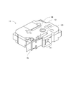
- the tape cassette 11 has an arm portion 13 that is a protruding portion of the cassette case 12.
- a cassette identification unit 14 is provided on the front surface of the arm unit 13.
- the cassette identification unit 14 indicates the type of the tape cassette 11 by the arrangement of holes formed in the front surface of the arm unit 13.
- the printing tape 15 is discharged from the tip of the arm part 13.
- a head insertion portion 16 is formed on the back side of the arm portion 13 and the back side of the printing tape 15.
- the roller holder 31 includes a movable conveyance roller 32, a platen roller 33, a side sensor 34, and the like. Further, the roller holder 31 has a shaft support portion 35. The shaft holder 35 receives rotation of a roller holder motor, which will be described later, directly or indirectly, so that the roller holder 31 is rotatably provided in the cassette mounting portion 6 (see FIG. 7) and rotates forward. Or reverse operation.
- the roller holder 31 when the roller holder 31 is rotated forward by the shaft support 35 or the like, if the tape cassette 11 (see FIG. 8) is mounted on the cassette mounting portion 6 (see FIG. 7), the tape cassette 11 (see FIG. 8 above).
- the roller holder 31 is pressed against the front surface of the arm portion 13 and the printing tape 15.
- the platen roller 33 of the roller holder 31 is pressed against the thermal head 7 (see FIG. 7) via the printing tape 15 of the tape cassette 11 (see FIG. 8).
- the side sensor 34 of the roller holder 31 is brought into pressure contact with the cassette identification section 14 of the tape cassette 11 (see FIG. 8), and can detect the type of the tape cassette 11 (see FIG. 8). .
- the roller holder 31 is rotated in the reverse direction by the shaft support portion 35 or the like, the roller holder 31 is released from the front surface of the arm portion 13 of the tape cassette 11 (see FIG. 8 above) or the printing tape 15.
- the platen roller 33 of the roller holder 31 is released from the printing tape 15 of the tape cassette 11 (see FIG. 8)
- the platen roller 33 is not pressed against the thermal head 7 (see FIG. 7).
- the side sensor 34 of the roller holder 31 is released from the cassette identification unit 14 of the tape cassette 11 (see FIG. 8), it is impossible to detect the type of the tape cassette 11 (see FIG. 8). It is said.
- the roller holder 31 can be rotated forward by the shaft support portion 35 and the like. It is also possible for the roller holder 31 to reversely rotate by the support portion 35 or the like.
- the tape printer 1 includes a control unit 60, a head drive circuit 68, a cutting motor drive circuit 69, a roller holder motor drive circuit 70, and a transport motor drive circuit 71.
- the control unit 60 includes a CPU 61, a CG-ROM 62, an EEPROM 63, a ROM 64, and a RAM 66. Further, the control unit 60, and the head driving circuit 68, the cutting motor drive circuit 69, a roller holder motor driving circuit 70, is connected to the transport motor drive circuit 71.
- the control unit 60, the connection interface 81, a communication interface 82, a keyboard 4, a liquid crystal display 5, the side sensor 34, the color sensor 41 is also connected to the cover sensor 42.
- the CPU 61 is a central processing unit that plays a central role in various controls in the tape printer 1 according to the present embodiment. Therefore, the CPU 61 is based on print data, control signals, various control programs, or the like input via the keyboard 4, the connection interface 81, or the communication interface 82. Display 5 etc.).
- CG-ROM 62 is a character generator memory for image data of the printed characters and symbols are stored in correspondence with code data with a dot pattern.
- the EEPROM 63 is a nonvolatile memory capable of writing / erasing stored contents.
- the ROM 64 stores various control programs and data in the tape printer 1 according to the present embodiment.
- the RAM 66 is a storage device that temporarily stores the calculation results in the CPU 61.
- the RAM 66 for example, print data input via the keyboard 4, the connection interface 81, or the communication interface 82 is stored. Further, the RAM 66 stores a cassette information variable described later.
- the connection interface 81 is for connecting a personal computer (not shown).
- the communication interface 82 is for receiving communication data from a peripheral device (not shown).
- the head drive circuit 68 is a circuit that controls the drive state of the thermal head 7 by supplying a drive signal to the thermal head 7 (see FIG. 7) based on a control signal from the CPU 61.
- Cutting motor drive circuit 69 supplies drive signals to the cutting motor 72 based on a control signal from the CPU 61, a circuit for controlling the driving of the cutting motor 72.
- a cutter (not shown) is driven, and the printing tape 15 (see FIG. 8) can be cut in the width direction.
- the roller holder motor drive circuit 70 is a circuit that controls the drive of the roller holder motor 73 by supplying a drive signal to the roller holder motor 73 based on a control signal from the CPU 61.
- the shaft support portion 35 of the roller holder 31 receives the drive directly or indirectly, and the roller holder 31 can be rotated forward or backward. it can. That is, the shaft support 35 of the roller holder 31 (see FIG. 9) is directly or indirectly connected to a roller holder motor 73.
- Conveying motor drive circuit 71 supplies drive signals to transport motor 74 based on a control signal from the CPU 61, a control circuit for controlling the driving of the conveying motor 74.
- a transport mechanism (not shown) is driven to transport the printing tape 15 (see FIG. 8 above).
- the side sensor 34 is provided on the roller holder 31 and is pressed against the cassette identification unit 14 of the tape cassette 11 (see FIG. 8) mounted on the cassette mounting unit 6 (see FIG. 7). Thus, the type of the tape cassette 11 is detected.
- the color sensor 41 detects color information (tape color, ink ribbon color, etc.) regarding the tape cassette 11 (see FIG. 8) mounted on the cassette mounting unit 6 (see FIG. 7).
- the detection principle of the color sensor 41 includes, for example, detecting a plurality of protruding pieces protruding from the tape cassette 11 being mounted on the cassette mounting portion 6, and based on the combination of the detected plurality of protruding pieces. Some color information (such as tape color and ink ribbon color) is detected.
- the cover sensor 42 detects the open / closed state of the cover 3 (see FIG. 7 above).
- the detection principle of the cover sensor 42 includes, for example, detecting a protruding piece protruding from the cover 3 and detecting the open / closed state of the cover 3 based on the presence or absence of the detection.
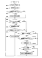
- the control program shown in the flowchart of FIG. 1 is a first main program, which is stored in the ROM 64 and the like and executed by the CPU 61. As shown in FIG. 1, in the first main program, first, in S11, a process at power-on is performed.
- cassette information variables are initialized in S101. Specifically, the cassette information variable secured in the RAM 66 is initialized. Thereafter, the process proceeds to S102. In S102, other power-on processing is performed.
- S12 it is determined whether or not the cover 3 is closed. This determination process is performed based on a detection signal from the cover sensor 42. If the cover 3 is open (S12: NO), the process proceeds to S14 described later. On the other hand, when the cover 3 is closed (S12: YES), the process proceeds to S13. In S13, a cassette detection process is performed.
- the roller holder 31 is pressure-bonded. That is, the roller holder 31 is rotated forward. At this time, if the tape cassette 11 is mounted on the cassette mounting portion 6, the platen roller 33 of the roller holder 31 is pressed against the thermal head 7 via the printing tape 15 of the tape cassette 11, and at the same time, the roller holder 31.
- the side sensor 34 is in pressure contact with the cassette identification section 14 of the tape cassette 11 and can detect the type of the tape cassette 11. Thereafter, the process proceeds to S112.
- the cassette is detected. Specifically, at this time, if the tape cassette 11 is mounted on the cassette mounting portion 6, information on the type of the tape cassette 11 is detected via the side sensor 34. Thereafter, the process proceeds to S113.
- the detected information is substituted into the cassette information variable. Specifically, if information relating to the type of the tape cassette 11 is detected in S112, the detected information is overwritten and stored in the cassette information variable of the RAM 66. Thereafter, the process proceeds to S114.
- the roller holder 31 is released. That is, the roller holder 31 is reversely operated. At this time, if the tape cassette 11 is mounted on the cassette mounting portion 6, the platen roller 33 of the roller holder 31 is released from the printing tape 15 of the tape cassette 11, so that it is not pressed against the thermal head 7. side sensor 34 of the roller holder 31, since it is released from the cassette identifying unit 14 of the tape cassette 11, is impossible to detect the type of the tape cassette 11.
- S14 it is determined whether or not the cover 3 is closed. This determination process is performed based on a detection signal from the cover sensor 42. At this time, if the cover 3 is closed (S14: YES), the process proceeds to S15.
- S16 it is determined whether print data has been received. In this determination, it is determined whether print data from a personal computer (not shown) is received via the connection interface 81. If print data has not been received (S16: NO), the process proceeds to S17 described later. On the other hand, if the print data is received (S16: YES), the process proceeds to S16-2.
- S16-2 it is determined whether or not the cover 3 is closed. This determination process is performed based on a detection signal from the cover sensor 42. If the cover 3 is open (S16-2: NO), the process proceeds to S17, which will be described later. On the other hand, when the cover 3 is closed (S16-2: YES), the process proceeds to S16-3.
- a printing process is performed.
- the print data determined to have been received in S16 is printed on the printing tape 15.
- the roller holder 31 is rotated forward, so that the platen roller 33 of the roller holder 31 It is pressed against the thermal head 7 via the printing tape 15.
- the roller holder 31 is rotated in the reverse direction, so that the platen roller 33 of the roller holder 31 is released from the printing tape 15 of the tape cassette 11, so that it is not pressed against the thermal head 7. Thereafter, the process proceeds to S17.
- S17 it is determined whether or not there is a cassette information transmission request. This request is made from a personal computer (not shown) via the connection interface 81. Here, when there is no request for transmission of cassette information (S17: NO), the process returns to S14 and the processes after S14 are repeated.
- the contents of the cassette information variable are returned in S121. Specifically, the contents of the cassette information variable in the RAM 66 are transmitted to a personal computer (not shown) via the connection interface 81. If no cassette is detected in S112, information “no cassette” is transmitted to the personal computer (not shown) via the connection interface 81 as the contents of the cassette information variable.
- the cassette is detected when the cover 3 is closed (S14: YES) or when the power is on and the cover 3 is closed (S12: YES).
- the roller holder 31 is pressure-bonded (S111)
- the tape cassette 11 is detected (S112)
- information on the type of the tape cassette 11 obtained by the detection is obtained. It is stored in the RAM 66 (S113).
- the roller holder 31 is released (S114), and a print standby state is set.
- the information about the type of the tape cassette 11 is needed: The (S17 YES), the information stored in the RAM66 is used (S121).
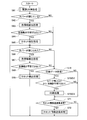
- the control program shown in the flowchart of FIG. 5 is a second main program, which is stored in the ROM 64 and executed by the CPU 61.
- S33 it is determined whether or not the color information is unknown. In this determination process, the detection signal acquired in S32 is treated as color information. If the color information is unknown (S33: NO), the process proceeds to S35 described later. On the other hand, if the color information is not unknown (S33: YES), the process proceeds to S34.
- S35 it is determined whether or not the state of the color sensor 41 has changed. This determination process is performed based on the detection signal acquired from the color sensor 41. If the state of the color sensor 41 has changed (S35: YES), the process proceeds to S36.
- S37 it is determined whether or not the color information is unknown. In this determination process, the detection signal acquired in S36 is treated as color information. If the color information is unknown (S37: NO), the process proceeds to S39 described later. On the other hand, if the color information is not unknown (S37: YES), the process proceeds to S38.
- S39 it is determined whether print data has been received. In this determination, it is determined whether print data from a personal computer (not shown) is received via the connection interface 81. Here, when print data is not received (S39: NO), it progresses to S40 mentioned later. On the other hand, when the print data is received (S39: YES), the process proceeds to S39-2.
- S39-2 it is determined whether or not the color information is unknown. In this determination process, the detection signal acquired in S32 or S36 is treated as color information. If the color information is unknown (S39: 2: NO), the process proceeds to S40 described later. On the other hand, if the color information is not unknown (S39-2: YES), the process proceeds to S39-3.
- a printing process is performed.
- the print data determined to be received in S39 is printed on the printing tape 15.
- the roller holder 31 is rotated forward so that the platen roller 33 of the roller holder 31 It is pressed against the thermal head 7 via the printing tape 15.
- the roller holder 31 is rotated in the reverse direction, so that the platen roller 33 of the roller holder 31 is released from the printing tape 15 of the tape cassette 11, so that it is not pressed against the thermal head 7. Thereafter, the process proceeds to S40.
- S40 it is determined whether or not there is a cassette information transmission request. This request is made from a personal computer (not shown) via the connection interface 81. Here, when there is no transmission request for the cassette information: The (S40 NO), the flow returns to S35, processing of S35 and later is repeated.
- cassette information transmission processing is performed. Since this cassette information transmission process is the same as the cassette information transmission process (S18) of the first operation, the description thereof is omitted.
- the state of the color sensor 41 changes (S35: YES) is considered as the time of replacement of the tape cassette 11
- the time of replacement of the tape cassette 11 is based on the detection signals (S32, S36) acquired from the color sensor 41. It is possible to detect Te, without using the cover sensor 42, it is possible to perform the cassette detection process (S34, S38) when replacing the tape cassette 11.
- control program shown in the flowchart of FIG. 6 is a third main program, and is stored in the ROM 64 and executed by the CPU 61.
- S62 it is determined whether or not the cover 3 is closed. This determination process is performed based on a detection signal from the cover sensor 42. If the cover 3 is open (S62: NO), the process proceeds to S66 described later. On the other hand, when the cover 3 is closed (S62: YES), the process proceeds to S63.
- S64 it is determined whether or not the color information is unknown. In this determination process, the detection signal acquired in S63 is treated as color information. If the color information is unknown (S64: NO), the process proceeds to S66 described later. On the other hand, if the color information is not unknown (S64: YES), the process proceeds to S65.
- S66 it is determined whether or not the cover 3 is closed. This determination process is performed based on a detection signal from the cover sensor 42. At this time, when the cover 3 is closed (S66: YES), the process proceeds to S67.
- S68 it is determined whether or not the color information is unknown. In this determination process, the detection signal acquired in S67 is treated as color information. If the color information is unknown (S68: NO), the process proceeds to S70 described later. On the other hand, if the color information is not unknown (S68: YES), the process proceeds to S69.
- S70 it is determined whether print data has been received. In this determination, it is determined whether print data from a personal computer (not shown) is received via the connection interface 81. Here, when print data is not received (S70: NO), it progresses to S71 mentioned later. On the other hand, if the print data is received (S70: YES), the process proceeds to S70-2.
- S70-2 it is determined whether the cover 3 is closed and the color information is not unknown. This determination process is performed based on a detection signal from the cover sensor 42. Further, in this determination process, the detection signal acquired in S63 or S67 is treated as color information.
- the cover 3 is opened, or when the color information is unknown (S70 of 2: NO)
- the process proceeds to S71 to be described later.
- the cover 3 has been closed, and, if the color information is not unknown (S70 of 2: YES), the process proceeds to 3 of S70.
- a printing process is performed.
- the print data determined to have been received in S70 is printed on the printing tape 15.
- the roller holder 31 is rotated forward to move the roller holder 31.
- the platen roller 33 is pressed against the thermal head 7 via the printing tape 15 of the tape cassette 11.
- the roller holder 31 is rotated in the reverse direction, so that the platen roller 33 of the roller holder 31 is released from the printing tape 15 of the tape cassette 11, so that it is not pressed against the thermal head 7. Thereafter, the process proceeds to S71.
- S71 it is determined whether or not there is a request for transmitting cassette information. This request is made from a personal computer (not shown) via the connection interface 81. Here, when there is no transmission request for the cassette information: The (S71 NO), the flow returns to S66, processing of S66 and later is repeated.
- cassette information transmission processing is performed. Since this cassette information transmission process is the same as the cassette information transmission process (S18) of the first operation, the description thereof is omitted.
- the cover 3 is closed (S66: YES) and the color information is not unknown (S68: YES), or when the power is turned on and the cover 3 is closed (S62: YES) and if the color information is not unknown (S64: YES), the cassette detecting process (S65, S69) is performed.
- the side sensor 34 detects the type of the tape cassette 11 when the roller holder 31 provided with the platen roller 33 and the side sensor 34 is pressed against the tape cassette 11. This is possible (S112).
- the cassette detection process (S13, S15, S34, S38, S65, S69) is performed.
- the roller holder 31 is brought into a pressure-bonded state with respect to the tape cassette 11 mounted on the cassette mounting portion 6 (S111). Is detected by the side sensor 34 (S112, S113), the roller holder 31 is released from the tape cassette 11 mounted on the cassette mounting unit 6 (S114), and the print standby state is set.
- the platen roller 33 provided in the roller holder 31 is never pressed against the thermal head 7, deformation of the platen roller 33 can be reduced.
- the CPU 61 performs printing with the thermal head 7 when performing the first operation in FIG. 1, the second operation in FIG. 5, or the third operation in FIG. 6.
- the cassette detection process (S13, S15, S34, S38, S65, S69) is also performed in cases other than the case (S16-3, S39-3, S70-3).
- the roller holder 31 is brought into a pressure-bonded state with respect to the tape cassette 11 mounted on the cassette mounting portion 6 (S111). Is detected by the side sensor 34 (S112, S113), the roller holder 31 is released from the tape cassette 11 mounted on the cassette mounting portion 6 (S114).
- a thermal head 7 (S16-3, S39-3, S70-3), even if the tape cassette 11 is replaced (S12: YES, S14: YES, S33: YES, S37: YES, S64: YES, S68: YES), cassette detection processing (S13, S15, S34, S38, Than to 65, S69) is performed, is it possible to detect the type of the tape cassette 11 by the side sensor 34.
- the CPU 61 performs printing with the thermal head 7 when performing the first operation in FIG. 1 or the third operation in FIG. 6 (S16-3, S70). 3), that is, when the cover sensor 42 detects that the cover 3 is closed (S12: YES, S14: YES, S62: YES, S66: YES), or the power supply of the tape printer 1
- cassette detection processing S13, S15, S65, S69
- the roller holder 31 is pressed against the tape cassette 11 mounted on the cassette mounting section 6 (S111), and the type of the tape cassette 11 is changed to the side.
- the roller holder 31 After detection by the sensor 34 (S112, S113), the roller holder 31 is released with respect to the tape cassette 11 mounted on the cassette mounting unit 6 (S114). For example, the thermal head 7 performs printing. Even if it is performed (S16-3, S70-3), the cassette detection process (S12: YES, S14: YES, S62: YES, S66: YES) will occur even if an opportunity to acquire the type of the tape cassette 11 is reached S13, S15, S65, and S69) can be performed, and the side sensor 3 Is it possible to detect the type of the tape cassette 11 by.
Landscapes
- Printers Characterized By Their Purpose (AREA)
- Handling Of Sheets (AREA)
- Handling Of Continuous Sheets Of Paper (AREA)
- Electronic Switches (AREA)
Abstract
La présente invention a pour objet de réduire la déformation d'un rouleau à platine dans un dispositif d'impression de bande quand un support à rouleau comportant le rouleau à platine et un capteur latéral est pincé par la cassette à bande, le dispositif d'impression de bande étant en mesure de détecter le type de cassette à bande à l'aide d'un capteur latéral. Le procédé de détection de cassette (S13, S15) est effectué quand l'impression est effectuée par une tête thermique (S16-3). Par ce procédé de détection de cassette (S13, S15), le support à rouleau est pincé sur la cassette à bande montée dans l'unité de montage de cassette, le type de cassette à bande est détecté par le capteur latéral, le support à rouleau est par la suite libéré de la cassette à bande montée dans l'unité de montage de cassette, et le dispositif est placé dans un état d'attente d'impression. Il est possible de réduire la déformation du rouleau à platine étant donné que le support à platine se trouvant sur le support à rouleau n'est pas comprimé en un contact constant avec la tête thermique.
Applications Claiming Priority (2)
| Application Number | Priority Date | Filing Date | Title |
|---|---|---|---|
| JP2011-060704 | 2011-03-18 | ||
| JP2011060704A JP2012196781A (ja) | 2011-03-18 | 2011-03-18 | テープ印刷装置 |
Publications (1)
| Publication Number | Publication Date |
|---|---|
| WO2012128018A1 true WO2012128018A1 (fr) | 2012-09-27 |
Family
ID=46879175
Family Applications (1)
| Application Number | Title | Priority Date | Filing Date |
|---|---|---|---|
| PCT/JP2012/055514 Ceased WO2012128018A1 (fr) | 2011-03-18 | 2012-03-05 | Dispositif d'impression de bande |
Country Status (2)
| Country | Link |
|---|---|
| JP (1) | JP2012196781A (fr) |
| WO (1) | WO2012128018A1 (fr) |
Citations (5)
| Publication number | Priority date | Publication date | Assignee | Title |
|---|---|---|---|---|
| JPH03270965A (ja) * | 1990-03-20 | 1991-12-03 | Mutoh Ind Ltd | サーマル記録装置 |
| JP2004130683A (ja) * | 2002-10-10 | 2004-04-30 | Brother Ind Ltd | 印刷装置、プログラム、及びそのプログラムを記録した記録媒体 |
| JP2005053182A (ja) * | 2003-08-07 | 2005-03-03 | Brother Ind Ltd | テープ印刷装置及びテープ印刷システム |
| JP2008179062A (ja) * | 2007-01-25 | 2008-08-07 | Brother Ind Ltd | テープ印刷装置及びテープ印刷プログラム |
| JP2011011403A (ja) * | 2009-06-30 | 2011-01-20 | Brother Industries Ltd | テープカセット |
-
2011
- 2011-03-18 JP JP2011060704A patent/JP2012196781A/ja active Pending
-
2012
- 2012-03-05 WO PCT/JP2012/055514 patent/WO2012128018A1/fr not_active Ceased
Patent Citations (5)
| Publication number | Priority date | Publication date | Assignee | Title |
|---|---|---|---|---|
| JPH03270965A (ja) * | 1990-03-20 | 1991-12-03 | Mutoh Ind Ltd | サーマル記録装置 |
| JP2004130683A (ja) * | 2002-10-10 | 2004-04-30 | Brother Ind Ltd | 印刷装置、プログラム、及びそのプログラムを記録した記録媒体 |
| JP2005053182A (ja) * | 2003-08-07 | 2005-03-03 | Brother Ind Ltd | テープ印刷装置及びテープ印刷システム |
| JP2008179062A (ja) * | 2007-01-25 | 2008-08-07 | Brother Ind Ltd | テープ印刷装置及びテープ印刷プログラム |
| JP2011011403A (ja) * | 2009-06-30 | 2011-01-20 | Brother Industries Ltd | テープカセット |
Also Published As
| Publication number | Publication date |
|---|---|
| JP2012196781A (ja) | 2012-10-18 |
Similar Documents
| Publication | Publication Date | Title |
|---|---|---|
| US20250121616A1 (en) | Printing device configured to determine reverse conveyance amount of printing medium based on control information acquired from cassette, and cassette attachable to the printing device | |
| JP7830723B2 (ja) | 記録装置、記録装置の制御方法、およびプログラム | |
| US10232643B2 (en) | Printing apparatus, control method and computer readable recording medium | |
| WO2012128018A1 (fr) | Dispositif d'impression de bande | |
| US9597908B2 (en) | Printer displays heating elements status and sets a check range to determine whether the heating elements is normal or abnormal | |
| JP6910129B2 (ja) | プリンタ | |
| JP7346914B2 (ja) | 印刷制御装置、印刷制御方法及びプログラム | |
| JP2002200806A (ja) | プリンタ及びその制御方法、並びにコンピュータ読み取り可能な情報記録媒体 | |
| US11034171B2 (en) | Printer and control method for printer | |
| JP2017094642A (ja) | 熱転写方式のプリンタ | |
| US20120162671A1 (en) | Tape printer and printing control method of tape printer | |
| JP7263877B2 (ja) | 印刷装置 | |
| JP2020196140A (ja) | 印刷装置の制御方法及び印刷装置 | |
| JP2020179538A (ja) | 印刷装置 | |
| US11491811B2 (en) | Printer | |
| US11850871B2 (en) | Mobile printer | |
| JP6918533B2 (ja) | プリンタ | |
| JP6198587B2 (ja) | 印刷システムおよび印刷システムの制御方法 | |
| US20180093514A1 (en) | Printer and recording medium | |
| JP7433942B2 (ja) | プリンタシステム、プリンタおよびホストコンピュータ | |
| JP4401073B2 (ja) | 印字装置 | |
| JP7192476B2 (ja) | 印刷装置、プログラム、及び、制御方法 | |
| JP2010012676A (ja) | 印刷装置およびテープ印刷装置 | |
| JP5987741B2 (ja) | 印刷装置、印刷装置の制御方法及び印刷装置の制御プログラム | |
| JP6130198B2 (ja) | 印刷機の紙情報読取方法 |
Legal Events
| Date | Code | Title | Description |
|---|---|---|---|
| 121 | Ep: the epo has been informed by wipo that ep was designated in this application |
Ref document number: 12760837 Country of ref document: EP Kind code of ref document: A1 |
|
| NENP | Non-entry into the national phase |
Ref country code: DE |
|
| 122 | Ep: pct application non-entry in european phase |
Ref document number: 12760837 Country of ref document: EP Kind code of ref document: A1 |