WO2012128020A1 - Dispositif d'entraînement de moteur pour véhicule, et automobile - Google Patents
Dispositif d'entraînement de moteur pour véhicule, et automobile Download PDFInfo
- Publication number
- WO2012128020A1 WO2012128020A1 PCT/JP2012/055522 JP2012055522W WO2012128020A1 WO 2012128020 A1 WO2012128020 A1 WO 2012128020A1 JP 2012055522 W JP2012055522 W JP 2012055522W WO 2012128020 A1 WO2012128020 A1 WO 2012128020A1
- Authority
- WO
- WIPO (PCT)
- Prior art keywords
- gear
- shaft
- speed
- control gear
- input
- Prior art date
- Legal status (The legal status is an assumption and is not a legal conclusion. Google has not performed a legal analysis and makes no representation as to the accuracy of the status listed.)
- Ceased
Links
Images






Classifications
-
- F—MECHANICAL ENGINEERING; LIGHTING; HEATING; WEAPONS; BLASTING
- F16—ENGINEERING ELEMENTS AND UNITS; GENERAL MEASURES FOR PRODUCING AND MAINTAINING EFFECTIVE FUNCTIONING OF MACHINES OR INSTALLATIONS; THERMAL INSULATION IN GENERAL
- F16H—GEARING
- F16H3/00—Toothed gearings for conveying rotary motion with variable gear ratio or for reversing rotary motion
- F16H3/02—Toothed gearings for conveying rotary motion with variable gear ratio or for reversing rotary motion without gears having orbital motion
- F16H3/08—Toothed gearings for conveying rotary motion with variable gear ratio or for reversing rotary motion without gears having orbital motion exclusively or essentially with continuously meshing gears, that can be disengaged from their shafts
- F16H3/10—Toothed gearings for conveying rotary motion with variable gear ratio or for reversing rotary motion without gears having orbital motion exclusively or essentially with continuously meshing gears, that can be disengaged from their shafts with one or more one-way clutches as an essential feature
-
- F—MECHANICAL ENGINEERING; LIGHTING; HEATING; WEAPONS; BLASTING
- F16—ENGINEERING ELEMENTS AND UNITS; GENERAL MEASURES FOR PRODUCING AND MAINTAINING EFFECTIVE FUNCTIONING OF MACHINES OR INSTALLATIONS; THERMAL INSULATION IN GENERAL
- F16D—COUPLINGS FOR TRANSMITTING ROTATION; CLUTCHES; BRAKES
- F16D41/00—Freewheels or freewheel clutches
- F16D41/06—Freewheels or freewheel clutches with intermediate wedging coupling members between an inner and an outer surface
- F16D41/08—Freewheels or freewheel clutches with intermediate wedging coupling members between an inner and an outer surface with provision for altering the freewheeling action
- F16D41/10—Freewheels or freewheel clutches with intermediate wedging coupling members between an inner and an outer surface with provision for altering the freewheeling action with self-actuated reversing
- F16D41/105—Freewheels or freewheel clutches with intermediate wedging coupling members between an inner and an outer surface with provision for altering the freewheeling action with self-actuated reversing the intermediate members being of circular cross-section, of only one size and wedging by rolling movement not having an axial component between inner and outer races, one of which is cylindrical
-
- F—MECHANICAL ENGINEERING; LIGHTING; HEATING; WEAPONS; BLASTING
- F16—ENGINEERING ELEMENTS AND UNITS; GENERAL MEASURES FOR PRODUCING AND MAINTAINING EFFECTIVE FUNCTIONING OF MACHINES OR INSTALLATIONS; THERMAL INSULATION IN GENERAL
- F16H—GEARING
- F16H2200/00—Transmissions for multiple ratios
- F16H2200/0021—Transmissions for multiple ratios specially adapted for electric vehicles
-
- F—MECHANICAL ENGINEERING; LIGHTING; HEATING; WEAPONS; BLASTING
- F16—ENGINEERING ELEMENTS AND UNITS; GENERAL MEASURES FOR PRODUCING AND MAINTAINING EFFECTIVE FUNCTIONING OF MACHINES OR INSTALLATIONS; THERMAL INSULATION IN GENERAL
- F16H—GEARING
- F16H2200/00—Transmissions for multiple ratios
- F16H2200/003—Transmissions for multiple ratios characterised by the number of forward speeds
- F16H2200/0034—Transmissions for multiple ratios characterised by the number of forward speeds the gear ratios comprising two forward speeds
Definitions
- the present invention relates to a vehicle motor drive device that shifts the rotation of an electric motor and transmits it to wheels, and an automobile equipped with the motor drive device.
- An electric motor, a transmission that changes the rotation of the electric motor, and a differential that distributes the rotation output from the transmission to left and right wheels as a vehicle motor driving device used in a drive device of an electric vehicle and a hybrid vehicle What consists of a gear is conventionally known (for example, patent document 1).
- this vehicle motor drive device When this vehicle motor drive device is used, it is possible to use the electric motor in a highly efficient rotational speed and torque region during driving and regeneration by switching the transmission gear ratio according to the running conditions. .
- the rotational speed of the rotating member of the transmission during high-speed traveling can be reduced, and the power loss of the transmission can be reduced to improve the energy efficiency of the vehicle.
- the vehicle motor drive device described in Patent Document 1 includes a friction clutch provided in each of two rotation transmission paths having different gear ratios, and a speed change actuator that selectively engages the friction clutch.
- the friction clutch is an arrangement in which a pressure plate connected to the upstream side of the rotation transmission path and a clutch plate connected to the downstream side of the rotation transmission path are arranged facing each other in the axial direction.
- the pressure plate is brought into contact with the clutch plate, the rotation is transmitted via the frictional force between the contact surfaces.
- the inventors of the present invention have studied a vehicle motor drive device using a two-way roller clutch instead of the above-described friction clutch as a clutch for switching between two rotation transmission paths having different gear ratios.
- a motor drive device for a vehicle the following configuration was devised.
- An electric motor an input shaft to which rotation of the motor shaft of the electric motor is input, an output shaft arranged parallel to the input shaft at an interval, a first-speed input gear and 2 provided on the input shaft A high-speed input gear, a first-speed output gear and a second-speed output gear that are provided on the output shaft and mesh with the first-speed input gear and the second-speed input gear, respectively, and a differential gear that distributes rotation of the output shaft to the left and right wheels
- the 1st speed output gear and the 2nd speed output gear are rotatably supported by the output shaft through bearings, A 1-speed 2-way roller clutch that switches between transmission and disconnection of torque between the first-speed output gear and the output shaft, and 2 that switches between transmission and disconnection of torque between the 2-speed output gear and the output shaft
- a vehicle motor drive apparatus provided with a speed change actuator that selectively engages a high-speed 2-way roller clutch, a first-speed 2-way roller clutch, and a 2-speed 2-way roller clutch.
- the first-speed two-way roller clutch is incorporated between the cam surface provided on the inner periphery of the first-speed output gear, the cylindrical surface provided on the outer periphery of the output shaft, and the cam surface and the cylindrical surface.
- the roller is held between the cam surface and the cylindrical surface, and is rotatable relative to the output shaft between a neutral position where the roller is disengaged.
- the first-speed cage is provided, and the transmission and interruption of torque can be switched by moving the first-speed cage in the circumferential direction between the engagement position and the neutral position. It is like that.
- the 2-speed 2-way roller clutch has the same configuration as the 1-speed 2-way roller clutch.
- This vehicle motor drive device operates the speed change actuator to release the engagement of the two-speed two-way roller clutch, and also engages the first-speed two-way roller clutch, thereby rotating the electric motor to the first speed. It is possible to change the gear ratio and transmit it to the wheels. In addition, by releasing the engagement of the first-speed two-way roller clutch and engaging the second-speed two-way roller clutch, the rotation of the electric motor is shifted at the second-speed gear ratio and transmitted to the wheels. Can do.
- the inventors of the present invention have investigated the cause of the noise and vibration, and one of the causes is that the motor shaft and the input shaft of the vehicle motor drive device are directly connected by a spline or key. I found out.
- the problem to be solved by the present invention is to suppress abnormal noise and vibration of a vehicle motor drive device using a two-way roller clutch as a clutch for switching between two rotation transmission paths having different gear ratios.
- an electric motor an input shaft to which rotation of the motor shaft of the electric motor is input, and a rotation transmission member that transmits rotation between the motor shaft and the input shaft;
- An output shaft disposed in parallel to the input shaft at an interval, a first input gear and a second input gear provided on the input shaft, and provided on the output shaft, A first output gear and a second output gear that mesh with the input gear and the second input gear, respectively, and a differential gear that distributes rotation of the output shaft to left and right wheels,
- One of the first input gear, the second input gear, and the input shaft set, and the first output gear, the second output gear, and the output shaft set are connected to the first control gear and the second output gear.
- Control gear and a control gear support shaft that rotatably supports these control gears via bearings,
- a first two-way roller clutch that switches between transmission and interruption of torque between the first control gear and the control gear support shaft; and torque between the second control gear and the control gear support shaft.
- a second 2-way roller clutch for switching between transmission and disconnection, and a transmission actuator for selectively engaging the first 2-way roller clutch and the second 2-way roller clutch;
- the first two-way roller clutch includes a cylindrical surface provided on one of the inner periphery of the first control gear and the outer periphery of the control gear support shaft, a cam surface provided on the other, the cam surface, The control between the roller incorporated between the cylindrical surfaces, the engagement position for holding the rollers and engaging the rollers between the cam surface and the cylindrical surface, and the neutral position for releasing the engagement of the rollers
- a first retainer provided so as to be rotatable relative to the gear support shaft, and a first switch spring for elastically retaining the first retainer in the neutral position;
- the second two-way roller clutch includes a cylindrical surface provided on one of the inner periphery of the second control gear and the outer periphery of the control gear support shaft, a cam surface provided on the other, the cam surface, The control between the roller incorporated between the cylindrical surfaces, the engagement position for
- the vehicle motor drive device adopting this configuration operates the shift actuator to release the engagement of the two-way roller clutch at the current shift stage and to engage the two-way roller clutch at the next shift stage,
- the rotation of the motor can be changed at the gear ratio of the next gear and transmitted to the wheels.
- the inertia of the motor shaft indirectly acts on the roller via the elastic member of the rotation transmitting member, and the inertia of the motor shaft is buffered by the deformation of the elastic member. Therefore, the force that pushes the roller between the cam surface and the cylindrical surface is not excessive, and abnormal noise and vibration are not easily generated.
- the motor shaft and the input shaft are connected via a plurality of gears and any one of the gears is used as the rotation transmission member
- the motor shaft and the input shaft are coaxially connected in series.
- the motor shaft and the input shaft are preferably coupled by the rotation transmission member.
- the rotation transmission member includes a first flange member that is prevented from rotating about the motor shaft, a second flange member that is disposed to face the first flange member and is prevented from rotating about the input shaft, and the first flange.
- an annular elastic member supported on the outer periphery of the support bolt and fitted in the accommodation hole can be employed.
- the elastic member for example, a rubber bush or a metal spring can be adopted.
- the rubber bush and a metal fitted to the inner periphery of the bush are used. It is preferable to employ a metal inner sleeve and a metal outer sleeve fitted to the outer periphery of the bush. If it does in this way, since the outer periphery and inner periphery of a bush are covered with a metal sleeve, it will become difficult to wear
- the elastic members are attached to the support bolts excluding a part of the plurality of support bolts, and the remaining support is supported.
- a rigid ring having an outer diameter smaller than that of the elastic member may be attached to the bolt. In this way, when a large load is applied to the rotation transmission member, the rigid ring contacts the inner periphery of the accommodation hole and supports a load above a certain level, so the load applied to the elastic member is suppressed, thereby improving the life of the elastic member.
- the rigid ring may be made of metal in order to ensure its durability.
- the rigid ring may be made of metal in order to ensure its durability.
- the first actuator is provided so as to be movable in the axial direction between a position where it is prevented from rotating with respect to the first retainer and is in contact with a side surface of the first control gear and a position where it is separated from the first control gear.
- the first friction plate a first separation spring that urges the first friction plate in a direction away from the side surface of the first control gear,
- a second friction plate provided so as to be movable in the axial direction between a position contacting the side surface of the second control gear and a position separating from the side surface, and the second friction plate is moved from the side surface of the second control gear.
- a second separation spring that urges in the direction of separation, a first shift position that presses the first friction plate and contacts a side surface of the first control gear, and a second friction plate Shifting in the axial direction between the second shift position and the second shift position contacting the side surface of the second control gear.
- a shift ring provided so as to be, can be adopted comprising a shift mechanism for moving the shift ring in the axial direction.
- the shift actuator having this configuration When the shift actuator having this configuration is employed, when the shift ring is at the first shift position, the first friction plate contacts the side surface of the first control gear, and the first friction gear between the contact surfaces causes the first friction plate to contact the first friction gear.
- the friction plate rotates relative to the control gear support shaft, and the first retainer that is prevented from rotating by the friction plate moves from the neutral position to the engagement position, so that the first two-way roller clutch is engaged. It becomes a state.
- the second friction plate since the second friction plate is separated from the side surface of the second control gear by the biasing force of the separation spring, the second retainer is held in the neutral position by the elastic force of the switch spring, The two-way roller clutch No. 2 is disengaged.
- the first friction plate When the shift ring is moved in the axial direction from the first shift position toward the second shift position by the operation of the shift mechanism, the first friction plate is moved to the side surface of the first control gear by the biasing force of the separation spring. Since the friction between the first friction plate and the first control gear is reduced, the first cage is moved from the engagement position to the neutral position by the elastic force of the switch spring, The engagement of the first two-way roller clutch is released by the movement of the first cage.
- the second friction plate comes into contact with the side surface of the second control gear, and the second friction plate is brought into contact with the control gear support shaft by the frictional force between the contact surfaces.
- the second cage that rotates relative to the friction plate and moves from the neutral position to the engaged position moves to the engaged state of the second 2-way roller clutch.
- At least one of a pair of left and right front wheels and a pair of left and right rear wheels is driven by the vehicle motor drive device. I will provide a.
- one of the pair of left and right front wheels and the pair of left and right rear wheels is driven by the engine, and the other is driven by the vehicle motor drive device. to provide a hybrid car that was to be.
- the inertia of the motor shaft indirectly acts on the roller via the elastic member of the rotation transmission member, and this occurs. Since the inertia of the motor shaft is buffered by the deformation of the elastic member, the force for pushing the roller between the cam surface and the cylindrical surface is unlikely to be excessive, and noise and vibration are unlikely to occur.
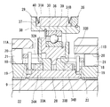
- FIG. 3 is an enlarged sectional view of the vicinity of the first-speed output gear and the second-speed output gear.
- FIG. 4 is a longitudinal sectional view along the second-speed switch spring of FIG.
- FIG. 4 is an enlarged sectional view in the vicinity of the shift ring. Enlarged sectional view of the rotation transmitting member near the 3 Sectional view along line VIII-VIII in FIG. Enlarged sectional view of the elastic member shown in FIG.
- FIG. 8 is an enlarged cross-sectional view showing an example in which a part of the elastic member of the rotation transmission member in FIG. 8 is replaced with a rigid ring. Enlarged sectional view of the rigid ring shown in FIG. 11 The figure which shows the state which the rigid ring shown in FIG. 11 contacts the inner periphery of an accommodation hole, and supports a load more than fixed.
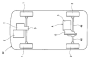
- FIG. 1 shows an electric vehicle EV in which a pair of left and right front wheels 1 are drive wheels driven by a vehicle motor drive device A according to the present invention, and a pair of left and right rear wheels 2 are driven wheels.
- FIG. 2 shows a hybrid vehicle HV in which a pair of left and right front wheels 1 are main drive wheels driven by an engine E, and a pair of left and right rear wheels 2 are auxiliary drive wheels driven by a vehicle motor drive device A according to the present invention. Indicates.
- the hybrid vehicle HV is provided with a transmission T that shifts the rotation of the engine E and a differential gear D that distributes the rotation output from the transmission T to the left and right front wheels 1.
- a vehicle motor drive device A according to the present invention incorporated in the electric vehicle EV and the hybrid vehicle HV will be described below.
- the motor drive device A includes an electric motor 3, a transmission 5 that changes the rotation of the motor shaft 4 of the electric motor 3, and the rotation output from the transmission 5 as shown in FIG. 1. It consists of a differential gear 6 that distributes to a pair of left and right front wheels 1 of a vehicle EV or distributes to a pair of left and right rear wheels 2 of a hybrid vehicle HV shown in FIG.
- the transmission 5 is parallel to the input shaft 7 with an interval between the input shaft 7 to which the rotation of the motor shaft 4 is input, a rotation transmission member 8 that transmits the rotation between the motor shaft 4 and the input shaft 7.
- An output shaft 9 disposed on the input shaft 7, a first speed input gear 10A and a second speed input gear 10B provided on the input shaft 7, and a first speed output gear 11A and a second speed output gear 11B provided on the output shaft 9. .
- the motor shaft 4 is coaxially arranged in series with the input shaft 7 and is rotationally driven by the stator 13 of the electric motor 3 fixed to the housing 12.
- the input shaft 7 is rotatably supported by a pair of opposed bearings 14 incorporated in the housing 12.
- the output shaft 9 is also rotatably supported by a pair of opposed bearings 15 incorporated in the housing 12.
- the first speed input gear 10 ⁇ / b> A and the second speed input gear 10 ⁇ / b> B are arranged at an interval in the axial direction, and are fixed to the input shaft 7 so as to rotate integrally with the input shaft 7 about the input shaft 7.
- the first-speed output gear 11A and the second-speed output gear 11B are also arranged at intervals in the axial direction.
- the first-speed output gear 11A and the second-speed output gear 11B are formed in an annular shape that penetrates the output shaft 9, are supported by the output shaft 9 via bearings 16 (see FIG. 4), and output is centered on the output shaft 9. is rotatable relative to the shaft 9.
- the first speed input gear 10A and the first speed output gear 11A mesh with each other, and rotation is transmitted between the first speed input gear 10A and the first speed output gear 11A.
- the 2nd speed input gear 10B and the 2nd speed output gear 11B are also meshed, and rotation is transmitted between the 2nd speed input gear 10B and the 2nd speed output gear 11B by the meshing.
- the reduction ratio between the second speed input gear 10B and the second speed output gear 11B is smaller than the reduction ratio between the first speed input gear 10A and the first speed output gear 11A.
- a first-speed two-way roller clutch 17A that performs torque transmission and switching between the first-speed output gear 11A and the output shaft 9 is used. Is incorporated. Further, between the second speed output gear 11B and the output shaft 9, there is incorporated a second speed two-way roller clutch 17B that switches between torque transmission and interruption between the second speed output gear 11B and the output shaft 9. .
- the second-speed two-way roller clutch 17B will be described below.
- the same reference numerals are given to the portions corresponding to the two-speed two-way roller clutch 17B, and the description thereof is omitted.
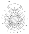
- the 2-speed 2-way roller clutch 17 ⁇ / b> B is provided on the cylindrical surface 20 provided on the inner periphery of the 2-speed output gear 11 ⁇ / b> B and on the outer periphery of the inner ring 19 that is prevented from rotating around the output shaft 9. It consists of a cam surface 18, a roller 21 incorporated between the cam surface 18 and the cylindrical surface 20, a retainer 22 that holds the roller 21, and a switch spring 23.
- the cam surface 18 is a surface that forms a wedge-shaped space that gradually narrows from the center in the circumferential direction toward both ends in the circumferential direction between the cam surface 18 and, for example, faces the cylindrical surface 20 as shown in the figure. It is a flat surface.
- the cage 22 is rotatably supported on the outer periphery of the inner ring 19, and is between an engagement position where the roller 21 is engaged between the cam surface 18 and the cylindrical surface 20 and a neutral position where the engagement of the roller 21 is released. It has become rotatable relative to the output shaft 9.
- the switch spring 23 includes a C-shaped annular portion 23a in which a steel wire is wound in a C shape, and extending portions 23b and 23b that extend radially outward from both ends of the C-shaped annular portion 23a.
- the C-shaped annular portion 23 a is fitted into a circular recess 24 formed on the axial end surface of the inner ring 19.
- the extending portion 23 b passes through a groove 25 formed on the end surface in the axial direction of the inner ring 19 so as to extend from the peripheral edge of the concave portion 24 to the outer diameter side, and the penetrating portion is formed in a notch 26 formed in the cage 22. Has been inserted.
- the groove 25 and the notch 26 are formed to have the same width.
- the extending portion 23b is in contact with the inner surface facing in the circumferential direction of the groove 25 and the inner surface facing in the circumferential direction of the notch 26, and the cage 22 is neutralized by a circumferential force acting on the contact surface. Elastically held in position.
- the position of the groove 25 and the position of the notch 26 are shifted in the circumferential direction, so that the distance between the pair of extending portions 23b, 23b.
- the C-shaped annular portion 23a is elastically deformed in the direction in which the width of the groove is narrowed, and the pair of extending portions 23b, 23b of the switch spring 23 presses the inner surface of the groove 25 and the inner surface of the notch 26 by the elastic restoring force, and is held by the pressing. A force in a direction to return the container 22 to the neutral position is applied.
- the inner ring 19 having the cam surface 18 of the first-speed two-way roller clutch 17A is formed in an annular shape that penetrates the output shaft 9, and is prevented from rotating around the output shaft 9 by spline fitting.
- An inner ring 19 having a cam surface 18 of the two-speed two-way roller clutch 17B is also formed in an annular shape that penetrates the output shaft 9, and is prevented from rotating around the output shaft 9 by spline fitting.
- the first-speed inner ring 19 and the second-speed inner ring 19 are not movable in the axial direction by a locking nut 27 fitted to the outer periphery of the output shaft 9.
- a spacer 28 is incorporated between the inner ring 19 on the first speed side and the inner ring 19 on the second speed side.
- the first-speed two-way roller clutch 17A and the second-speed two-way roller clutch 17B can be selectively engaged by a transmission actuator 29.
- the speed change actuator 29 includes a shift ring 30 that is movably provided in the axial direction between the first speed output gear 11A and the second speed output gear 11B, and the first speed output gear 11A and the shift ring 30.
- the first speed friction plate 31A is provided with a notch 33A that engages with a protrusion 32A formed on the first speed side retainer 22, and the engagement of the protrusion 32A and the notch 33A makes the first speed friction plate 31A one. Rotation is prevented by the fast cage 22. Further, the first speed friction plate 31A can move in the axial direction between a position contacting the side surface of the first speed output gear 11A and a position separating from the position while the protrusion 32A and the notch 33A are engaged. ing.
- the second speed friction plate 31B is also provided with a notch 33B that engages with a protrusion 32B formed on the second speed side retainer 22, and the engagement of the protrusion 32B with the notch 33B makes the second speed friction plate 31B 2 Rotation is prevented by the fast cage 22. Further, the second speed friction plate 31B is supported so as to be movable in the axial direction between a position contacting the side surface of the second speed output gear 11B and a position separating from the position while the protrusion 32B and the notch 33B are engaged. Has been.
- a separation spring 34A is incorporated between the first speed friction plate 31A and the inner ring 19 on the first speed side in a compressed state in the axial direction, and the first speed friction plate 31A is 1 by the elastic restoring force of the separation spring 34A. It is urged in a direction away from the side surface of the high-speed output gear 11A.
- a separation spring 34B is incorporated between the second speed friction plate 31B and the inner ring 19 on the second speed side in a state of being compressed in the axial direction, and the second speed friction plate 31B is caused by the elastic restoring force of the separation spring 34B.
- the second-speed output gear 11B is biased in a direction away from the side surface.
- the shift ring 30 presses the first speed friction plate 31A to contact the side surface of the first speed output gear 11A, and the shift ring 30 presses the second speed friction plate 31B to contact the side surface of the second speed output gear 11B. It is supported so as to be movable in the axial direction between the speed shift position. Further, a shift mechanism 35 that moves the shift ring 30 in the axial direction between the first-speed shift position and the second-speed shift position is provided.
- the shift mechanism 35 includes a shift motor (not shown), a bifurcated shift fork 36 connected to the shift motor via a motion conversion mechanism, and a shift sleeve 38 having an annular groove 37 fitted to the shift fork 36 on the outer periphery.
- the rolling sleeve 39 is assembled to the inner periphery of the shift sleeve 38 so as to be non-movable in the axial direction, and rotatably supports the shift ring 30.
- a motion conversion mechanism feed screw mechanism or the like
- a preload spring 40 that is compressible in the axial direction is incorporated.
- a differential drive gear 41 that transmits the rotation of the output shaft 9 to the differential gear 6 is fixed to the output shaft 9.
- the differential gear 6 includes a differential case 43 that is rotatably supported by a bearing 42, a ring gear 44 that is fixed to the differential case 43 coaxially with the rotational center of the differential case 43, meshed with the differential drive gear 41, and a right angle with the rotational center of the differential case 43.
- the pinion shaft 45 fixed to the differential case 43 in any direction, a pair of pinions 46 rotatably supported by the pinion shaft 45, and a pair of left and right side gears 47 meshing with the pair of pinions 46.
- the left side gear 47 is connected to the shaft end portion of the axle 48 connected to the left wheel
- the right side gear 47 is connected to the shaft end portion of the axle 48 connected to the right wheel.
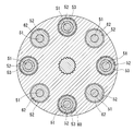
- the rotation transmitting member 8 includes a disk-shaped first flange member 49, a disk-shaped second flange member 50 disposed to face the first flange member 49, and a second A plurality of support bolts 51 fixed at equal intervals in the circumferential direction on the surface of the flange member 50 facing the first flange member 49, and the second flange member 50 of the first flange member 49 so as to penetrate each support bolt 51.
- a plurality of receiving holes 52 formed on the surface facing each other, and an annular elastic member 53 which is attached to the outer periphery of the support bolt 51 and fits into the receiving hole 52.
- the accommodation holes 52 are formed so that the inner periphery is cylindrical, and each accommodation hole 52 has the same inner diameter.
- the end of the motor shaft 4 is a spline shaft in which a plurality of protrusions extending in the axial direction are formed at equal intervals in the circumferential direction.
- a spline hole 54 is formed in which a plurality of grooves extending in the axial direction are formed at equal intervals in the circumferential direction.
- the spline hole 54 is spline-fitted to the motor shaft 4, and the first flange member 49 is prevented from rotating around the motor shaft 4 by the spline fitting, and when the motor shaft 4 rotates, the first flange member 49 is connected to the motor shaft 4.
- axis 4 and is adapted to rotate integrally.
- a spline hole 55 in which a plurality of grooves extending in the axial direction are formed at equal intervals in the circumferential direction is formed at the shaft end of the input shaft 7.
- a spline shaft 56 is formed in which a plurality of protrusions extending in the axial direction are formed at equal intervals in the circumferential direction.
- the spline shaft 56 is spline-fitted in the spline hole 55, and the second flange member 50 is prevented from rotating around the input shaft 7 by the spline fitting, and when the second flange member 50 rotates, the input shaft 7 The two flange members 50 are rotated together.
- a boss portion 50 a protruding in a columnar shape is formed on the side surface of the second flange member 50 on the input shaft 7 side, and the outer periphery of the boss portion 50 a is rotatably supported by the housing 12 via a bearing 57. Yes.
- the elastic member 53 includes a rubber bush 58, a metal inner sleeve 59 fitted to the inner periphery of the bush 58, and a metal outer sleeve fitted to the outer periphery of the bush 58.
- the bush 58 is a cylindrical rubber molded body, and has an axial end face having a shape in which a cross section along the radial direction is recessed in an arc shape. Further, the inner diameter surface of the bush 58 is vulcanized and bonded to the outer diameter surface of the inner sleeve 59, and the outer diameter surface of the bush 58 is also vulcanized and bonded to the inner diameter surface of the outer sleeve 60.
- the support bolt 51 includes a screw shaft portion 51a having an external thread on the outer periphery, a cylindrical shaft portion 51b having a larger diameter than the screw shaft portion 51a, and a head portion 51c having a larger diameter than the cylindrical shaft portion 51b.
- the screw shaft portion 51a is screwed into the screw hole 61 formed in the second flange member 50.
- the inner sleeve 59 is slightly longer in the axial direction than the cylindrical shaft portion 51 b of the support bolt 51, and when the support bolt 51 is screwed into the screw hole 61, the inner sleeve 59 is the head of the support bolt 51. 51c is pressed against the side surface of the second flange member 50, and the inner sleeve 59 is fixed by the pressing force.
- the elastic member 53 having the above configuration allows relative rotational displacement between the motor shaft 4 and the input shaft 7 by elastic deformation. That is, when the rotation speed of one of the motor shaft 4 and the input shaft 7 changes suddenly while the motor shaft 4 and the input shaft 7 are rotating, the bush 58 of the elastic member 53 is elastically deformed, Due to the elastic deformation, the center of each support bolt 51 and the center of each accommodation hole 52 are eccentric, and a relative rotational displacement occurs between the motor shaft 4 and the input shaft 7.
- the first speed friction plate 31A is separated from the side surface of the first speed output gear 11A, and the second speed friction plate 31B is also separated from the side surface of the second speed output gear 11B.
- the retainer 22 is held in the neutral position by the elastic force of the first-speed switch spring 23, and the second-speed retainer 22 is also held in the neutral position by the elastic force of the second-speed switch spring 23.
- the first-speed two-way roller clutch 17A is disengaged from the roller 21, and the second-speed two-way roller clutch 17B is also disengaged from the roller 21.
- the first speed friction plate 31A becomes 1 by the urging force of the separation spring 34A. Since the friction between the first-speed friction plate 31A and the first-speed output gear 11A is reduced by moving away from the side surface of the high-speed output gear 11A, the first-speed side holding is performed by the elastic force of the first-speed switch spring 23. The device 22 moves from the engagement position to the neutral position, and the engagement of the first-speed two-way roller clutch 17A is released by the movement of the first-speed retainer 22.
- the rotation transmission member 8 is provided with an elastic member 53 that allows relative rotational displacement between the motor shaft 4 and the input shaft 7 by elastic deformation.
- the inertia of the motor shaft 4 indirectly acts on the roller 21 via the elastic member 53, and the deformation of the elastic member 53 causes the motor shaft 4 to move. Since the inertia is buffered, the force for pushing the roller 21 between the cam surface 18 and the cylindrical surface 20 is unlikely to be excessive, and abnormal noise and vibration are unlikely to occur. The same applies when the 2-speed 2-way roller clutch 17B is engaged.
- the vehicle motor drive device A of this embodiment when regenerative braking is performed with the electric motor 3 or when the electric motor 3 accelerates after stopping regenerative braking, torque generated by the electric motor 3 is generated. Since the elastic member 53 is buffered by the deformation of the elastic member 53 and acts on the roller 21, when the pushing direction of the roller 21 between the cam surface 18 and the cylindrical surface 20 is switched between forward and reverse, the roller 21 is moved to the cam surface 18 and the cylindrical surface 20. The force that pushes in between is not excessive, and abnormal noise and vibration are less likely to occur.
- the motor shaft 4 and the input shaft 7 are connected via a plurality of gears, and any one of the gears is used as the rotation transmission member 8.
- the motor shaft 4 and the input shaft 7 are preferably arranged in series on the same axis, and the motor shaft 4 and the input shaft 7 are coupled by the rotation transmission member 8. In this way, the inertia acting on the roller 21 when the first-speed two-way roller clutch 17A or the second-speed two-way roller clutch 17B is engaged can be minimized, and abnormal noise and vibration are effectively prevented. Can be prevented.
- the elastic member 53 for example, it is possible to employ only a rubber bush or a metal spring, but as shown in this embodiment, the rubber bush 58 and the bush 58 It is preferable to employ a metal inner sleeve 59 fitted to the inner periphery and a metal outer sleeve 60 fitted to the outer periphery of the bush 58. In this way, since the outer periphery and inner periphery of the bush 58 are covered with the metal sleeves 59, 60, the rubber bush 58 is less likely to be worn, and the durability required for automobile parts can be ensured. Become. Further, when a metal spring is used as the elastic member 53, the spring may resonate and noise may be generated. However, as shown in this embodiment, when the rubber bush 58 is used, resonance does not occur and abnormal noise is generated. Does not occur.
- the rotation transmission member 8 in which the elastic member 53 is attached to all the support bolts 51 among the plurality of support bolts 51 has been described as an example.
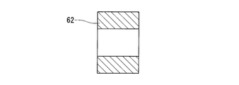
- the elastic members 53 may be attached to the support bolts 51 excluding a part of them, and the rigid rings 62 having an outer diameter smaller than that of the outer sleeve 60 of the elastic members 53 may be attached to the remaining support bolts 51.
- the rigid ring 62 contacts the inner periphery of the accommodation hole 52 and supports a load above a certain level as shown in FIG. The load applied to the member 53 is suppressed, and the life of the elastic member 53 can be improved.
- the rigid ring 62 may be a cylindrical body made of metal in order to ensure its durability.
- the rigid ring 62 is heavier than the elastic member 53, if the rigid rings 62 are arranged at equal intervals in the circumferential direction as shown in FIG. 11, the weight balance of the rotation transmission device can be achieved, and the rotation transmission member 8 vibrations can be prevented.
Landscapes
- Engineering & Computer Science (AREA)
- General Engineering & Computer Science (AREA)
- Mechanical Engineering (AREA)
- Structure Of Transmissions (AREA)
- Hybrid Electric Vehicles (AREA)
- Electric Propulsion And Braking For Vehicles (AREA)
Abstract
Afin de supprimer des bruits étranges et des vibrations dans un dispositif d'entraînement de moteur de véhicule à l'aide d'un embrayage à rouleaux bidirectionnel en tant qu'embrayage pour commuter entre deux chemins de transmission de rotation ayant différents rapports d'engrenage, l'invention porte sur un dispositif d'entraînement de moteur de véhicule avec une structure comprenant : un élément de transmission de rotation (8) pour la transmission d'une rotation entre un arbre moteur (4) et un arbre d'entrée (7) ; un engrenage d'entrée de pignon de première vitesse (10A) et un engrenage d'entrée de pignon de deuxième vitesse (10B) disposés sur l'arbre d'entrée (7) ; et, un engrenage de sortie de pignon de première vitesse (11A) et un engrenage de sortie de pignon de deuxième vitesse (11B) qui viennent en prise avec l'engrenage d'entrée de pignon de première vitesse (10A) et l'engrenage d'entrée de pignon de deuxième vitesse (10B) respectivement. Ici, un embrayage à rouleaux bidirectionnel de pignon de première vitesse est disposé entre l'engrenage de sortie de pignon de première vitesse (11) et un arbre de sortie (9) et un embrayage à rouleaux bidirectionnel de pignon de deuxième vitesse (17B) est disposé entre l'engrenage de sortie de pignon de deuxième vitesse (11B) et l'arbre de sortie (9), et l'élément de transmission de rotation (8) comprend un élément élastique (53) qui permet un déplacement en rotation relatif entre l'arbre moteur (4) et l'arbre d'entrée (7) au moyen d'une déformation élastique.
Applications Claiming Priority (2)
| Application Number | Priority Date | Filing Date | Title |
|---|---|---|---|
| JP2011060144A JP2012193823A (ja) | 2011-03-18 | 2011-03-18 | 車両用モータ駆動装置および自動車 |
| JP2011-060144 | 2011-03-18 |
Publications (1)
| Publication Number | Publication Date |
|---|---|
| WO2012128020A1 true WO2012128020A1 (fr) | 2012-09-27 |
Family
ID=46879177
Family Applications (1)
| Application Number | Title | Priority Date | Filing Date |
|---|---|---|---|
| PCT/JP2012/055522 Ceased WO2012128020A1 (fr) | 2011-03-18 | 2012-03-05 | Dispositif d'entraînement de moteur pour véhicule, et automobile |
Country Status (2)
| Country | Link |
|---|---|
| JP (1) | JP2012193823A (fr) |
| WO (1) | WO2012128020A1 (fr) |
Cited By (3)
| Publication number | Priority date | Publication date | Assignee | Title |
|---|---|---|---|---|
| CN103104660A (zh) * | 2012-09-29 | 2013-05-15 | 刘培生 | 一种机械动力变速器 |
| US20130296129A1 (en) * | 2011-01-07 | 2013-11-07 | Yoshinori Itakura | Motor drive assembly for a vehicle and a motor vehicle |
| CN116867983A (zh) * | 2021-03-10 | 2023-10-10 | 株式会社F.C.C. | 离合器装置及其使用的离合器外壳 |
Families Citing this family (1)
| Publication number | Priority date | Publication date | Assignee | Title |
|---|---|---|---|---|
| CN105041987A (zh) * | 2015-06-29 | 2015-11-11 | 无锡市神力齿轮冷挤有限公司 | 纯电动汽车用减速器 |
Citations (4)
| Publication number | Priority date | Publication date | Assignee | Title |
|---|---|---|---|---|
| JPS5951239U (ja) * | 1982-09-29 | 1984-04-04 | 株式会社小松製作所 | ダンパ装置 |
| JPH07317848A (ja) * | 1994-05-27 | 1995-12-08 | Honda Motor Co Ltd | 電動車両用トランスミッション |
| WO2010150851A1 (fr) * | 2009-06-24 | 2010-12-29 | 株式会社ユニバンス | Dispositif de commande pour véhicule |
| WO2011030670A1 (fr) * | 2009-09-08 | 2011-03-17 | Ntn株式会社 | Dispositif d'entraînement motorisé moteur pour véhicule, et automobile |
-
2011
- 2011-03-18 JP JP2011060144A patent/JP2012193823A/ja not_active Withdrawn
-
2012
- 2012-03-05 WO PCT/JP2012/055522 patent/WO2012128020A1/fr not_active Ceased
Patent Citations (4)
| Publication number | Priority date | Publication date | Assignee | Title |
|---|---|---|---|---|
| JPS5951239U (ja) * | 1982-09-29 | 1984-04-04 | 株式会社小松製作所 | ダンパ装置 |
| JPH07317848A (ja) * | 1994-05-27 | 1995-12-08 | Honda Motor Co Ltd | 電動車両用トランスミッション |
| WO2010150851A1 (fr) * | 2009-06-24 | 2010-12-29 | 株式会社ユニバンス | Dispositif de commande pour véhicule |
| WO2011030670A1 (fr) * | 2009-09-08 | 2011-03-17 | Ntn株式会社 | Dispositif d'entraînement motorisé moteur pour véhicule, et automobile |
Cited By (5)
| Publication number | Priority date | Publication date | Assignee | Title |
|---|---|---|---|---|
| US20130296129A1 (en) * | 2011-01-07 | 2013-11-07 | Yoshinori Itakura | Motor drive assembly for a vehicle and a motor vehicle |
| US9033851B2 (en) * | 2011-01-07 | 2015-05-19 | Ntn Corporation | Motor drive assembly for a vehicle and a motor vehicle |
| CN103104660A (zh) * | 2012-09-29 | 2013-05-15 | 刘培生 | 一种机械动力变速器 |
| CN116867983A (zh) * | 2021-03-10 | 2023-10-10 | 株式会社F.C.C. | 离合器装置及其使用的离合器外壳 |
| CN116867983B (zh) * | 2021-03-10 | 2024-07-12 | 株式会社F.C.C. | 离合器装置及其使用的离合器外壳 |
Also Published As
| Publication number | Publication date |
|---|---|
| JP2012193823A (ja) | 2012-10-11 |
Similar Documents
| Publication | Publication Date | Title |
|---|---|---|
| JP2012219852A (ja) | 車両用モータ駆動装置および自動車 | |
| JP5465614B2 (ja) | 車両用モータ駆動装置および自動車 | |
| US9033851B2 (en) | Motor drive assembly for a vehicle and a motor vehicle | |
| US9234566B2 (en) | Transmission | |
| US11493128B2 (en) | Motive power transmission route switching device and two-speed transmission | |
| WO2012137812A1 (fr) | Appareil d'entraînement de moteur de véhicule, et automobile | |
| US8850928B2 (en) | Power takeoff unit for automobile | |
| WO2010143740A1 (fr) | Dispositif de transmission de puissance | |
| WO2011030689A1 (fr) | Automobile électrique | |
| JP5474456B2 (ja) | 車両用モータ駆動装置および自動車 | |
| WO2012128020A1 (fr) | Dispositif d'entraînement de moteur pour véhicule, et automobile | |
| WO2012165146A1 (fr) | Procédé de commande du changement de rapports pour appareil de propulsion de véhicule à moteur électrique, et procédé de commande du changement de rapports pour véhicule | |
| JP2013130266A (ja) | 車両用モータ駆動装置 | |
| WO2012128243A1 (fr) | Dispositif d'entraînement de moteur pour véhicule, et automobile | |
| US11982340B2 (en) | Two-speed transmission | |
| US20250305546A1 (en) | Two-speed transmission | |
| JP2008045601A (ja) | 動力伝達装置 | |
| JP2013108613A (ja) | クラッチ及び四輪駆動車 | |
| JP4194287B2 (ja) | ギアプレート式アクチュエータ及びこれを用いた動力断続装置及びデファレンシャル装置 | |
| JP3477506B2 (ja) | オンオフ式トルクリミッタ | |
| JP4848978B2 (ja) | ベルト式無段変速機 | |
| CN223411326U (zh) | 一种制动钳传动机构及车辆 | |
| US20260061822A1 (en) | Power transmission device | |
| JP2020128771A (ja) | 駆動力伝達装置及び四輪駆動車 | |
| JP2013024379A (ja) | 差動装置 |
Legal Events
| Date | Code | Title | Description |
|---|---|---|---|
| 121 | Ep: the epo has been informed by wipo that ep was designated in this application |
Ref document number: 12760175 Country of ref document: EP Kind code of ref document: A1 |
|
| NENP | Non-entry into the national phase |
Ref country code: DE |
|
| 122 | Ep: pct application non-entry in european phase |
Ref document number: 12760175 Country of ref document: EP Kind code of ref document: A1 |