WO2012128023A1 - Structure d'amortisseur pour réfrigérateur à adsorption - Google Patents
Structure d'amortisseur pour réfrigérateur à adsorption Download PDFInfo
- Publication number
- WO2012128023A1 WO2012128023A1 PCT/JP2012/055632 JP2012055632W WO2012128023A1 WO 2012128023 A1 WO2012128023 A1 WO 2012128023A1 JP 2012055632 W JP2012055632 W JP 2012055632W WO 2012128023 A1 WO2012128023 A1 WO 2012128023A1
- Authority
- WO
- WIPO (PCT)
- Prior art keywords
- adsorption
- condenser
- evaporator
- desorption
- damper
- Prior art date
- Legal status (The legal status is an assumption and is not a legal conclusion. Google has not performed a legal analysis and makes no representation as to the accuracy of the status listed.)
- Ceased
Links
Images



Classifications
-
- F—MECHANICAL ENGINEERING; LIGHTING; HEATING; WEAPONS; BLASTING
- F25—REFRIGERATION OR COOLING; COMBINED HEATING AND REFRIGERATION SYSTEMS; HEAT PUMP SYSTEMS; MANUFACTURE OR STORAGE OF ICE; LIQUEFACTION SOLIDIFICATION OF GASES
- F25B—REFRIGERATION MACHINES, PLANTS OR SYSTEMS; COMBINED HEATING AND REFRIGERATION SYSTEMS; HEAT PUMP SYSTEMS
- F25B17/00—Sorption machines, plants or systems, operating intermittently, e.g. absorption or adsorption type
- F25B17/08—Sorption machines, plants or systems, operating intermittently, e.g. absorption or adsorption type the absorbent or adsorbent being a solid, e.g. salt
-
- F—MECHANICAL ENGINEERING; LIGHTING; HEATING; WEAPONS; BLASTING
- F25—REFRIGERATION OR COOLING; COMBINED HEATING AND REFRIGERATION SYSTEMS; HEAT PUMP SYSTEMS; MANUFACTURE OR STORAGE OF ICE; LIQUEFACTION SOLIDIFICATION OF GASES
- F25B—REFRIGERATION MACHINES, PLANTS OR SYSTEMS; COMBINED HEATING AND REFRIGERATION SYSTEMS; HEAT PUMP SYSTEMS
- F25B2500/00—Problems to be solved
- F25B2500/01—Geometry problems, e.g. for reducing size
-
- Y—GENERAL TAGGING OF NEW TECHNOLOGICAL DEVELOPMENTS; GENERAL TAGGING OF CROSS-SECTIONAL TECHNOLOGIES SPANNING OVER SEVERAL SECTIONS OF THE IPC; TECHNICAL SUBJECTS COVERED BY FORMER USPC CROSS-REFERENCE ART COLLECTIONS [XRACs] AND DIGESTS
- Y02—TECHNOLOGIES OR APPLICATIONS FOR MITIGATION OR ADAPTATION AGAINST CLIMATE CHANGE
- Y02A—TECHNOLOGIES FOR ADAPTATION TO CLIMATE CHANGE
- Y02A30/00—Adapting or protecting infrastructure or their operation
- Y02A30/27—Relating to heating, ventilation or air conditioning [HVAC] technologies
-
- Y—GENERAL TAGGING OF NEW TECHNOLOGICAL DEVELOPMENTS; GENERAL TAGGING OF CROSS-SECTIONAL TECHNOLOGIES SPANNING OVER SEVERAL SECTIONS OF THE IPC; TECHNICAL SUBJECTS COVERED BY FORMER USPC CROSS-REFERENCE ART COLLECTIONS [XRACs] AND DIGESTS
- Y02—TECHNOLOGIES OR APPLICATIONS FOR MITIGATION OR ADAPTATION AGAINST CLIMATE CHANGE
- Y02B—CLIMATE CHANGE MITIGATION TECHNOLOGIES RELATED TO BUILDINGS, e.g. HOUSING, HOUSE APPLIANCES OR RELATED END-USER APPLICATIONS
- Y02B30/00—Energy efficient heating, ventilation or air conditioning [HVAC]
Definitions
- the present invention relates to a damper structure that opens and closes a communication path between a plurality of adsorption / desorption devices, an evaporator, and a condenser in an adsorption refrigerator.
- the heat transfer tubes are inserted into the two adsorption / desorption devices, and in each adsorption / desorption device, a solid adsorbent such as silica gel is disposed on the surface of the heat transfer tubes.
- a solid adsorbent such as silica gel is disposed on the surface of the heat transfer tubes.
- the evaporator and the condenser can be individually communicated with each of the adsorption / desorption devices by using the opening and closing of the damper.
- each adsorption / desorption device, evaporator, and condenser are in a vacuum state, and a refrigerant can flow between them.
- the adsorption refrigeration machine alternates an adsorption / desorption device that allows cooling water to flow through the heat transfer tubes and functions as an adsorber, and an adsorption / desorption device that functions as desorption devices by flowing hot water through the heat transfer tubes at predetermined time intervals. The operation is switched to.
- each communication path there are a plurality of valves disclosed in the temperature control method of the adsorption refrigerator of Patent Document 1.
- the plurality of valves open and close using a pressure difference formed between each adsorption / desorption device and an evaporator or a condenser.
- Each valve has a structure that allows the refrigerant vapor to flow only in one direction.
- a valve disposed in the communication path between each adsorption / desorption device and the evaporator enables the flow of refrigerant vapor from the evaporator to the adsorption / desorption device, while the adsorption / desorption device to the evaporator It has a structure that prevents the refrigerant vapor from flowing backward.
- a valve disposed in the communication path between each adsorption / desorption device and the condenser enables the circulation of the refrigerant vapor from the adsorption / desorption device to the condenser, while the refrigerant vapor from the condenser to each adsorption / desorption device. Has a structure that does not flow backward.
- a valve body as a damper is formed in a shell shape having a curved surface, and a communication port for disposing the valve body is formed in a conical taper shape. Then, due to the dynamic pressure of the refrigerant in one direction generated between the spaces partitioned by the valve body, the curved surface of the outer periphery of the valve body comes into contact with the surface of the conical tapered communication port, thereby closing the communication port. ing. Further, the valve body is lifted from the communication port by the dynamic pressure of the refrigerant in the other direction generated between the spaces, thereby opening the communication port. Further, the valve body is prevented from flowing by the dynamic pressure of the refrigerant flowing through each space by the valve guide.
- the present invention has been made in view of such conventional problems, and can reduce the weight of the damper and improve the durability. Between each adsorption / desorption device, the evaporator, and the condenser, the present invention can be realized. It is an object of the present invention to provide a damper structure for an adsorption refrigeration machine that can stably open and close each communication path by an appropriate pressure difference.
- One aspect of the present invention includes a plurality of adsorption / desorption devices formed by inserting heat transfer tubes having a solid adsorbent disposed on the surface, an evaporator capable of individually communicating with the plurality of adsorption / desorption devices, A condenser capable of communicating individually with the adsorption / desorption device, the cooling / adsorbing device flowing through the heat transfer tube to function as an adsorber, and the warming water flowing through the heat transfer tube to function as a desorption device
- the evaporator-side communication path formed between each of the adsorption / desorption devices and the evaporator is formed in an inclined shape so that the evaporator side is lower than each of the adsorption / desorption devices.
- the condenser side communication path formed between the condenser and the condenser is formed in an inclined shape so that the condenser side is higher than the respective adsorption / desorption side,
- a spherical damper is movably disposed in each communication path which is the evaporator side communication path or the condenser side communication path,
- a ring-shaped sealing material whose inner periphery is closed by the spherical damper is provided on the inclined lower end side in the passage formation direction of each communication passage,
- a damper structure for an adsorption refrigeration machine wherein a stopper for preventing the spherical damper from slipping out of each communication path is provided on the inclined upper end side in the path formation direction of each communication path. It is in.
- the evaporator-side communication path and the condenser-side communication path are formed in an inclined shape, and spherical dampers formed in a spherical shape are movably disposed in these. Further, a ring-shaped sealing material is provided on the inclined lower end side in the passage forming direction of each communication passage, and a stopper is provided on the inclined upper end side in the passage forming direction of each communication passage.
- each adsorption / desorption device, the evaporator and the condenser In the adsorption refrigerator, the inside of each adsorption / desorption device, the evaporator and the condenser is in a vacuum state, and each adsorption / desorption device, the evaporator and the condenser are connected to each other through each communication path. Refrigerant vapor can be distributed.
- the spherical damper can move in the communication path as follows.
- an adsorption / desorption device in which cooling water is supplied to the heat transfer tube and functions as an adsorber, the solid adsorbent is cooled by the heat transfer tube, and the refrigerant vapor is adsorbed to the solid adsorbent by an adsorption reaction (exothermic reaction).
- the pressure in this adsorption machine becomes lower than the pressure in an evaporator, and the pressure in a condenser, when the pressure in this adsorption machine falls.
- the spherical damper disposed in the evaporator side communication path receives a pressure difference in which the pressure in the adsorber is lower than the pressure in the evaporator, and is separated from the ring-shaped sealing material. Then, it moves to the inclined upper end side (from the evaporator side to the adsorber side) of the evaporator side communication path. Thereby, the evaporator side communication path is opened.
- the spherical damper disposed in the condenser side communication path receives its own weight and a pressure difference in which the pressure in the adsorber is lower than the pressure in the condenser, and the condenser side communication path It moves to the inclination lower end side (from the condenser side to the adsorber side). Thereby, this spherical damper rolls until it closes the inner periphery of the ring-shaped sealing material, and the condenser side communication path is closed. This closed state can be maintained by a pressure difference in which the pressure in the desorber is lower than the pressure in the condenser.
- each spherical damper can open the evaporator side communication path to the evaporator and close the condenser side communication path to the condenser.
- the solid adsorbent is heated by the heat transfer tube, and the refrigerant vapor is desorbed from the solid adsorbent by a desorption reaction (endothermic reaction).
- the pressure in this desorber rises, the pressure in this desorber becomes higher than the pressure in an evaporator and the pressure in a condenser.
- the spherical damper disposed in the condenser side communication path is separated from the ring-shaped sealing material by receiving a pressure difference in which the pressure in the desorber is higher than the pressure in the condenser. Then, it moves to the inclined upper end side (from the desorber side to the condenser side) of the condenser side communication path. Thereby, the condenser side communication path is opened.
- the spherical damper disposed in the evaporator side communication path moves to the inclined lower end side (from the desorber side to the evaporator side) of the evaporator side communication path by its own weight.
- this spherical damper rolls until it closes the inner periphery of the ring-shaped sealing material, and the evaporator side communication path is closed.
- This closed state can be maintained by a pressure difference in which the pressure in the desorber is higher than the pressure in the evaporator.
- each spherical damper can open the evaporator side communication path to the condenser and close the condenser side communication path to the evaporator.
- the spherical damper in each communication passage mainly rolls and moves through these pressure change processes. However, depending on the speed of change in the pressure difference applied to the spherical damper and the size of its own weight, it is considered that the spherical damper may slide and move.
- the spherical damper is mainly driven by its own weight from the inclined upper end side to the inclined lower end side. It is thought to roll. Further, since a stopper is provided on the inclined upper end side of each communication path, it is possible to prevent the spherical damper that moves to the inclined upper end side due to the pressure difference from slipping out of the communication path.
- the spherical damper uses the pressure difference generated between the adsorption / desorption device that functions as an adsorber and the evaporator, and between the adsorption / desorption device that functions as a desorption device, and the condenser.
- the communication path can be closed using its own weight. Therefore, it is not necessary to use a separate drive source for driving the spherical damper.
- the spherical damper has an extremely simple shape such as a spherical shape, and is easy to manufacture and lightweight.
- the spherical damper has a spherical shape, it is considered that the spherical damper moves along the communication path with shaking, slipping, and the like due to the flow of the refrigerant vapor. Therefore, the direction of the spherical damper can be appropriately changed when sealing the ring-shaped sealing material. Thereby, it can prevent that only the same location of a spherical damper wears by repeating a contact with a ring-shaped sealing material, and can improve durability of a spherical damper. Further, since the spherical damper has a spherical shape, refrigerant vapor does not accumulate and its own weight does not increase.
- the pressure difference between each adsorption / desorption device, the evaporator, and the condenser can be maintained at an appropriate pressure difference, and each communication path can be stably opened and closed by the spherical damper. Furthermore, the pressure difference for moving the spherical damper can be arbitrarily adjusted by changing the mass of the spherical damper, changing the inclination angle of each communication passage, or the like.
- the weight of the damper can be reduced and the durability can be improved, and an appropriate effect generated between each adsorption / desorption device, the evaporator and the condenser can be obtained.
- Each communication path can be stably opened and closed by a small pressure difference.
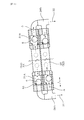
- BRIEF DESCRIPTION OF THE DRAWINGS The block diagram which shows schematically the adsorption-type refrigerator which uses the 1st adsorption / desorption device concerning an Example as an adsorber, and operates a 2nd adsorption / desorption device as a desorption device.
- BRIEF DESCRIPTION OF THE DRAWINGS The block diagram which shows schematically the adsorption
- FIG. 6 is an explanatory view showing each communication path in a state where a spherical damper is omitted according to the embodiment as seen from the direction of arrows AA in FIG. 5.
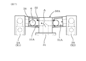
- FIG. Example of a vertical adsorption refrigerator that operates with the first adsorption / desorption device as the desorption device and the second adsorption / desorption device as the adsorption device, around each adsorption / desorption device and the condenser side communication path FIG.
- the evaporator side communication path is configured so that when the adsorption / desorption device functions as the adsorber, the spherical damper has an inclined upper end when the pressure in the adsorber becomes lower than the pressure in the evaporator.
- the suction / desorption device functions as the desorption device
- the spherical damper is Due to its own weight, it moves to the inclined lower end side and is closed, and the condenser side communication path is configured such that when the adsorption / desorption device functions as the desorption device, the pressure in the desorption device is higher than the pressure in the condenser.
- the spherical damper moves toward the upper end of the slope and is opened.
- the pressure in the adsorber becomes the pressure in the condenser.
- the spherical damper is It is preferably configured to be closed by moving into the inclined lower side by the weight. In this case, each spherical damper can be easily moved in each communication port by the pressure difference and the own weight applied to the inclined surface of the communication path.
- the spherical damper is preferably made of resin, and the ring-shaped sealing material is preferably a rubber packing. In this case, it is possible to easily reduce the weight of the spherical damper. Moreover, a ring-shaped sealing material can be formed at low cost.
- the spherical damper can be either a solid shape filled with resin up to the inside or a shell shape having a cavity inside depending on the size of the weight, the material, etc.
- a fitting prevention stopper for preventing the spherical damper from fitting into the ring-shaped sealing material and preventing it from coming off can be provided on the inclined lower end side of each communication passage.
- the spherical damper is fitted when the inner circumference of the ring-shaped sealing material is closed by moving to the inclined lower end side due to the pressure difference generated between each adsorption / desorption device, the evaporator and the condenser.
- the prevention stopper can prevent the ring-shaped sealing material from being fitted.
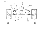
- the damper structure 5 of this example opens and closes the communication passages 51A and 51B formed between the adsorption / desorption devices 2A and 2B and the evaporator 31 and the condenser 32 in the adsorption refrigerator 1. . As shown in FIG. 1 and FIG.
- the adsorption refrigerator 1 includes a plurality of adsorption / desorption devices 2A and 2B formed by inserting a heat transfer tube 21 having a solid adsorbent 211 disposed on the surface, and a plurality of adsorption / desorption devices 2A, 2B, an evaporator 31 that can communicate with each other individually, and a condenser 32 that can communicate with each of the plurality of adsorption / desorption devices 2A and 2B.
- the adsorption / desorption device 2A (or 2B) that functions as a desorption device 2 and the adsorption / desorption device 2B (or 2A) that functions as the desorption device X2 by flowing warm water H through the heat transfer tube 21 are alternately switched at predetermined time intervals. It is configured as follows.
- the evaporator side communication path 51A formed between the adsorption / desorption devices 2A, 2B and the evaporator 31 is lower on the evaporator 31 side than the adsorption / desorption devices 2A, 2B side.
- the condenser side communication path 51B formed between the adsorption / desorption devices 2A, 2B and the condenser 32 is formed on the condenser 32 side as compared with the adsorption / desorption devices 2A, 2B side. It is formed in an inclined shape so as to be higher.
- the spherical damper 6 is arranged to roll in each of the communication paths 51A and 51B that are the evaporator side communication path 51A or the condenser side communication path 51B.
- a ring-shaped sealing material 55 that can block the inner periphery with the spherical damper 6 is provided on the lower end side of the communication passages 51A and 51B in the passage formation direction L.
- a stopper 56 for preventing the spherical damper 6 from slipping out of the communication passages 51A and 51B is provided on the inclined upper end side in the passage formation direction L of the communication passages 51A and 51B.
- FIG. 1 is a configuration diagram schematically showing an adsorption refrigerator 1 that operates with the first adsorption / desorption device 2A as the adsorber X1 and the second adsorption / desorption device 2B as the desorption device X2.
- FIG. 2 is a configuration diagram schematically showing an adsorption refrigeration machine 1 that operates with the first adsorption / desorption device 2A as the desorption device X2 and the second adsorption / desorption device 2B as the adsorption device X1.
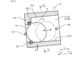
- each communicating path 51A, 51B and the spherical damper 6 are shown schematically.
- the adsorption refrigeration machine 1 of this example includes two adsorption / desorption devices 2A and 2B formed by inserting a heat transfer tube 21 having a solid adsorbent 211 disposed on the surface, and two adsorption / desorption devices 2A, An evaporator 31 that can communicate individually with 2B and a condenser 32 that can communicate individually with the two adsorption / desorption devices 2A and 2B are provided.
- the refrigerant A can be circulated inside each of the adsorption / desorption devices 2A and 2B, the evaporator 31 and the condenser 32, and the inside of each of the adsorption / desorption devices 2A and 2B, the evaporator 31 and the condenser 32 is a refrigerant. It is in a vacuum state so that A easily evaporates.
- the inside of the evaporator 31 is about 1/100 atm, and the inside of the condenser 32 is about 1/20 atm.
- the solid adsorbent 211 in this example is silica gel, and the refrigerant A is water.
- the evaporator 31 is provided adjacent to one side of the two adsorption / desorption devices 2A and 2B, and the condenser 32 is provided adjacent to the other side of the two adsorption / desorption devices 2A and 2B.
- the spherical damper 6 disposed in the evaporator side communication path 51A between each of the adsorption / desorption devices 2A, 2B and the evaporator 31 is closed from the side of each of the adsorption / desorption devices 2A, 2B toward the evaporator 31 by its own weight. It has been.
- the spherical damper 6 is configured to open only when the pressure in each of the adsorption / desorption devices 2A and 2B is lower than the pressure in the evaporator 31.
- the spherical damper 6 disposed in the condenser side communication path 51B between each adsorption / desorption device 2A, 2B and the condenser 32 is closed by its own weight from the condenser 32 side toward each adsorption / desorption device 2A, 2B side. It has been.
- the spherical damper 6 is configured to open only when the pressure in each of the adsorption / desorption devices 2A and 2B becomes higher than the pressure in the condenser 32.
- the heat transfer tubes 21 of the adsorption / desorption devices 2A and 2B are connected to two sets of switching valve devices 46A and 46B.
- An evaporator pipe 311 through which the cold water W passes is inserted in the evaporator 31, and the evaporator pipe 311 is connected to the cold water tank 44.
- the evaporation pipe 311 is connected to a refrigeration facility 45 as an object to be cooled for cooling by supplying cold water W.
- the refrigeration equipment 45 can be an air conditioning system, a refrigerator, or the like.
- the evaporation pipe 311 is circulated through the evaporator 31, the cold water tank 44, and the refrigeration equipment 45.
- a condenser tube 321 through which the cooling water C passes is inserted in the condenser 32, and the condenser tube 321 is connected to the cooling water tank 41.
- the cooling water C is supplied from the cooling water tank 41 to the condensing pipe 321 after passing through the switching valve device 46A, the heat transfer pipe 21 and the switching valve device 46B of each of the adsorption / desorption devices 2A and 2B, and from the condensing pipe 321 to the cooling water tank. 41 is circulated.
- the condenser 32 there is provided a tray 35 that receives the refrigerant A (water in this example) condensed and liquefied by the condenser tube 321.
- a circulation pipe 36 for supplying the refrigerant A accumulated in the tray 35 to the surface of the evaporation pipe 311 in the evaporator 31 is provided between the tray 35 and the evaporator 31.
- the hot water H supplied to the heat transfer tubes 21 of each of the adsorption / desorption devices 2A and 2B is heated using exhaust heat emitted from the heat generating equipment 42 that generates heat.
- the heat generating equipment 42 can be a solar heat utilization system, a gas engine system, a boiler, or equipment for generating steam drain.
- the hot water H is made using the exhaust heat from the heat generating equipment 42, stored in the hot water tank 43, and then supplied to the inlets of the heat transfer tubes 21 of the adsorption / desorption devices 2A and 2B via the switching valve device 46A. It has become so.
- the hot water H is circulated from the outlet of the heat transfer tube 21 of each of the adsorption / desorption devices 2A and 2B to the heat generating equipment 42 via the switching valve device 46B.
- the cooling water C is water at 25 to 35 ° C. (about 30 ° C.), and the hot water H is water heated to 70 to 90 ° C. (about 80 ° C.). Further, the cold water W in the evaporation pipe 311 of the evaporator 31 is cooled to 9 to 14 ° C. (about 11 ° C.).
- the adsorption refrigerator 1 has an adsorption / desorption device 2A (or 2B) that allows cooling water C to flow through the heat transfer tube 21 to function as the adsorption device X1, and an adsorption / desorption that causes warm water H to flow through the heat transfer tube 21 to function as the desorption device X2.
- the chilled water W in the evaporation pipe 311 inserted through the evaporator 31 is cooled by switching the apparatus 2B (or 2A) alternately at predetermined time intervals by operating the two switching valve devices 46A and 46B. It is configured to Thereby, the adsorption refrigeration machine 1 continuously supplies the generated cold water W from the cold water tank 44 to the refrigeration equipment 45.
- FIG. 5 is an explanatory view showing the communication passages 51A and 51B in which the spherical damper 6 is arranged.
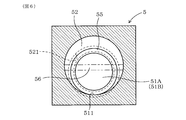
- FIG. 6 shows the communication passages 51A and 51B in a state where the spherical damper 6 is omitted, along the line AA in FIG. It is explanatory drawing shown in the state seen from the arrow direction.
- the spherical damper 6 of this example is made of a resin such as polypropylene, and is formed in a solid shape filled with resin up to the inside.
- the mass of the spherical damper 6 can be appropriately adjusted by appropriately changing the material, or by appropriately changing the absolute sizes of the ring-shaped sealing material 55 and the spherical damper 6.
- the inclined upper end side or the inclined lower end side means the upper end side or the lower end side in the passage formation direction L of each of the communication passages 51A and 51B.
- the upper surface side or lower surface side means the upper surface side or lower surface side in the vertical direction.
- the inclined upper end side is indicated by an arrow L1
- the inclined lower end side is indicated by an arrow L2.
- Each of the communication passages 51A and 51B of this example has a passage cross-sectional area at the end on the inclined lower end side that is smaller than the passage cross-sectional area of the general portion including the inclined upper end side.
- a stepped portion 52 is formed at the end on the inclined lower end side, and an annular groove 521 for holding the ring-shaped sealing material 55 is formed at the end on the inclined upper end side of the stepped portion 52. .
- the ring-shaped sealing material 55 of this example is a rubber packing.
- the cross-sectional area of each communication path 51A, 51B is larger than the diameter of the spherical damper 6, and when the spherical damper 6 rolls through each communication path 51A, 51B, A gap 53 is formed.
- the ring-shaped sealing material 55 is arranged so as to be biased toward the lower surface side of the stepped portion 52 of each communication passage 51A, 51B.
- the spherical damper 6 that rolls the bottom portion 511 of each communication passage 51 ⁇ / b> A, 51 ⁇ / b> B from the inclined upper end side to the inclined lower end side contacts the entire inner periphery of the ring-shaped sealing material 55. It is like that.
- the relative size of the ring-shaped sealing material 55 with respect to the spherical damper 6 is determined so that the inner peripheral diameter of the ring-shaped sealing material 55 is not less than 0.5 times and less than 0.8 times the diameter of the spherical damper 6. Can do.
- the stopper 56 of this example is provided so as to extend in the left-right direction at the end of the upper end side of each communication passage 51A, 51B.
- the stopper 56 can also be provided in a ring shape so that its upper end is floated in the space of each communication passage 51A, 51B.
- the stopper 56 can have various shapes that can stop the rolling of the spherical damper 6 while keeping the communication passages 51 ⁇ / b> A and 51 ⁇ / b> B open.
- each communication passage 51A, 51B When the inclination angle ⁇ of each communication passage 51A, 51B is moderated, the spherical damper 6 can be easily rolled to the inclination upper end side of each communication passage 51A, 51B by being pushed by the pressure of the refrigerant vapor A. However, if the inclination angle ⁇ of each of the communication passages 51A and 51B is made too gentle, the position of the spherical damper 6 in each of the communication passages 51A and 51B may not be stabilized due to the pressure of the refrigerant vapor A. On the other hand, when the inclination angle ⁇ of each of the communication passages 51A and 51B is made steep, an effect opposite to these occurs.
- the mass of the spherical damper 6 is reduced, the spherical damper 6 is pushed by the pressure of the refrigerant vapor A, so that the spherical damper 6 can easily roll to the inclined upper end side of each of the communication passages 51A and 51B.
- the mass of the spherical damper 6 is too small, the position of the spherical damper 6 in each of the communication passages 51A and 51B may not be stabilized due to the pressure of the refrigerant vapor A.
- the mass of the spherical damper 6 is increased, the opposite effect occurs.
- each of the communication passages 51A and 51B is made too steep, or if the mass of the spherical damper 6 is made too large, the force with which the spherical damper 6 comes into contact with the ring-shaped sealing material 55 becomes strong. Therefore, the spherical damper 6 may not be able to open the inner periphery of the ring-shaped sealing material 55 due to a pressure difference generated between the adsorption / desorption devices 2A and 2B and the evaporator 31 and the condenser 32.
- each communication passage 51A, 51B and the mass of the spherical damper 6 are large in the pressure difference generated between the adsorption / desorption devices 2A, 2B and the evaporator 31 and the condenser 32. In consideration of this, it is decided appropriately.
- the inclination angle ⁇ of each communication path 51A, 51B can be set to, for example, 1 to 15 ° with respect to the horizontal direction.
- a fitting prevention stopper 57 for preventing the spherical damper 6 from fitting into the ring-shaped sealing material 55 and preventing it from coming off is provided on the inclined lower end side of each communication passage 51A, 51B. be able to.
- the spherical damper 6 rolls on the inclined downstream side due to the pressure difference generated between the adsorption / desorption devices 2A and 2B, the evaporator 31 and the condenser 32, and moves the inner periphery of the ring-shaped sealing material 55.
- the fitting prevention stopper 57 can prevent the ring-shaped sealing material 55 from being fitted.
- the damper structure 5 including the communication paths 51A and 51B in which the spherical damper 6 is disposed can be applied to various adsorption refrigerators 1.
- the adsorption refrigeration machine 1 of this example is a horizontal adsorption refrigeration machine 1 in which a first adsorption / desorption device 2A and a second adsorption / desorption device 2B are opposed to each other in a substantially horizontal direction. Can be arranged.
- the first adsorbing / desorbing device 2A and the second adsorbing / desorbing device 2B are disposed in a state slightly inclined with respect to the horizontal direction.
- FIG. 3 shows the adsorption / desorption devices 2A and 2B for the horizontal adsorption refrigerator 1 that operates with the first adsorption / desorption device 2A as the adsorber X1 and the second adsorption / desorption device 2B as the desorption device X2.
- FIG. 4 shows the adsorption / desorption devices 2A and 2B and the communication units of the horizontal adsorption refrigerator 1 that operates with the first adsorption / desorption device 2A as the desorption device X2 and the second adsorption / desorption device 2B as the adsorption device X1.
- the evaporator 31 and the condenser 32 are disposed below the passage forming members 58A and 58B.
- the evaporator-side communication path 51A is provided with the evaporator 31 side inclined downward with respect to each of the adsorption / desorption devices 2A and 2B at the same angle as the inclination of each of the adsorption / desorption devices 2A and 2B.
- the condenser side communication path 51B is provided with the evaporating side inclined upward relative to the adsorption / desorption devices 2A and 2B at the same angle as the inclination of the adsorption / desorption devices 2A and 2B.
- the ring-shaped sealing material 55 is positioned on the inclined lower end side
- the stopper 56 is positioned on the inclined upper end side.
- the evaporator side communication path 51 ⁇ / b> A is configured so that the pressure in the adsorber X ⁇ b> 1 is higher than the pressure in the evaporator 31 when the adsorption / desorption device 2 ⁇ / b> A (or 2 ⁇ / b> B) functions as the adsorber X ⁇ b> 1.
- the spherical damper 6 rolls and opens toward the upper end of the slope, and when the adsorption / desorption device 2A (or 2B) functions as the desorption device X2, the pressure in the desorption device X2 is reduced to the condenser.
- the condenser-side communication path 51B is spherical when the pressure in the desorber X2 becomes higher than the pressure in the condenser 32 when the adsorber / desorber 2A (or 2B) functions as the desorber X2.
- the damper 6 rolls to the inclined upper end side and is opened while the adsorption / desorption device 2A (or 2B) functions as the adsorber X1 the pressure in the adsorber X1 is lower than the pressure in the condenser 32.
- the spherical damper 6 rolls to the inclined lower end side by its own weight and is closed.
- the adsorption refrigeration machine 1 is a vertical adsorption refrigeration machine 1 in which a first adsorption / desorption device 2 ⁇ / b> A and a second adsorption / desorption device 2 ⁇ / b> B are vertically arranged with a predetermined space therebetween. It can also be arranged in a state extending in the direction.
- FIG. 7 shows the adsorption / desorption devices 2A, 2A, and 2B for the vertical adsorption refrigerator 1 that operates with the first adsorption / desorption device 2A as the adsorber X1 and the second adsorption / desorption device 2B as the desorption device X2.
- FIG. 8 shows the adsorption and desorption devices 2A and 2B and the condensation of the vertical adsorption refrigerator 1 that operates with the first adsorption / desorption device 2A as the adsorber X1 and the second adsorption / desorption device 2B as the desorption device X2.
- FIG. 8 shows the adsorption and desorption devices 2A and 2B and the condensation of the vertical adsorption refrigerator 1 that operates with the first adsorption / desorption device 2A as the adsorber X1 and the second adsorption / desorption device 2B as the desorption device X2.
- the vertical adsorption refrigerator 1 an evaporator side for piping to the evaporator 31 between the upper end of the first adsorption / desorption device 2A and the upper end of the second adsorption / desorption device 2B.
- a passage forming member 58A see FIG.
- the evaporator 31 is disposed below the evaporator side passage forming member 58A between the first adsorption / desorption device 2A and the second adsorption / desorption device 2B, and the evaporator side communication passage 51A
- a side passage forming member 58A is provided at a portion connected to each of the adsorption / desorption devices 2A and 2B.
- Each evaporator-side communication passage 51A is provided so as to be inclined downward from the horizontal direction where the adsorption / desorption devices 2A and 2B are located to the horizontal center where the evaporator 31 is located.
- the condenser 32 is disposed above the condenser-side passage forming member 58B, and the condenser-side communication passage 51B is provided at a portion where the condenser-side passage forming member 58B is connected to each of the adsorption / desorption devices 2A and 2B. .
- the condenser side communication passage 51B is provided so as to be inclined downward from the horizontal center where the condenser 32 is located outward in the horizontal direction where the adsorption / desorption devices 2A and 2B are located.
- the spherical damper 6 disposed in each communication passage 51A, 51B opens and closes each communication passage 51A, 51B as follows when the adsorption refrigerator 1 is operated.
- the first adsorption / desorption device 2A functions as the adsorber X1.
- the solid adsorbent 211 arranged on the surface of the heat transfer tube 21 in the first adsorption / desorption device 2A is cooled, and the refrigerant vapor A is adsorbed on the solid adsorbent 211 by an adsorption reaction.
- the pressure in the 1st adsorption / desorption device 2A becomes lower than the pressure in the evaporator 31 and the pressure in the condenser 32 when the pressure in the 1st adsorption / desorption device 2A falls.
- the spherical damper 6A disposed in the evaporator side communication path 51A has a pressure in the first adsorption / desorption device 2A.
- it is separated from the ring-shaped sealing material 55, and rolls to the inclined upper end side (from the evaporator 31 side to the adsorber X 1 side) of the evaporator side communication path 51 A. It will be. Thereby, the evaporator side communication path 51A is opened.
- the refrigerant vapor A in the evaporator 31 flows into the first adsorption / desorption device 2 ⁇ / b> A, and heat as vaporization heat is removed from the surface of the evaporation pipe 311 in the evaporator 31.
- the cold water W in 311 can be cooled.
- the spherical damper 6B disposed in the condenser side communication passage 51B is inclined by the dead weight of the condenser side communication passage 51B. It rolls to the lower end side (from the condenser 32 side to the adsorber X1 side). Thereby, this spherical damper 6B rolls until it closes the inner periphery of the ring-shaped sealing material 55, and the condenser side communication path 51B is closed. This closed state can be maintained by a pressure difference in which the pressure in the first adsorption / desorption device 2A is lower than the pressure in the condenser 32.
- the spherical dampers 6A and 6B can open the evaporator-side communication path 51A between the evaporator 31 and the condenser 32. It is possible to close the condenser side communication path 51B.
- the hot water H is supplied to the heat transfer tube 21 in the second adsorption / desorption device 2B.
- the second adsorption / desorption device 2B functions as the desorption device X2.
- the solid adsorbent 211 disposed on the surface of the heat transfer tube 21 in the second adsorption / desorption device 2B is heated, and the refrigerant vapor A is desorbed from the solid adsorbent 211 by a desorption reaction.
- the pressure in the 2nd adsorption / desorption device 2B rises, the pressure in the 2nd adsorption / desorption device 2B becomes higher than the pressure in the evaporator 31 and the pressure in the condenser 32.
- the spherical damper 6D disposed in the condenser side communication passage 51B has a pressure in the desorption device X2 within the condenser 32.
- the ring-shaped sealing material 55 is separated from the ring-shaped sealing material 55 and rolls toward the inclined upper end side (from the desorber X2 side to the condenser 32 side) of the condenser side communication passage 51B. Thereby, the condenser side communication path 51B is opened.
- FIG. 3 in the second adsorption / desorption device 2B functioning as the desorption device X2
- the spherical damper 6D disposed in the condenser side communication passage 51B has a pressure in the desorption device X2 within the condenser 32.
- the ring-shaped sealing material 55 is separated from the ring-shaped sealing material 55 and rolls toward the inclined upper end side (from the desorber X2 side to the condenser 32 side) of the condenser side communication passage 51B.
- the refrigerant vapor A in the second adsorption / desorption device 2 ⁇ / b> B flows into the condenser 32, and this refrigerant vapor A is condensed by the cooling water C flowing through the condensation pipe 321 in the condenser 32.
- the condensed refrigerant vapor A is circulated into the evaporator 31 through the circulation pipe 36.
- the spherical damper 6C disposed in the evaporator-side communication passage 51A receives its own weight and receives the evaporator-side communication passage 51A. Rolling to the lower side of the slope (from the desorber X2 side to the evaporator 31 side). Thereby, this spherical damper 6C rolls until it closes the inner periphery of the ring-shaped sealing material 55, and the evaporator side communication path 51A is closed.
- This closed state can be maintained by a pressure difference in which the pressure in the second adsorption / desorption device 2B is higher than the pressure in the evaporator 31.
- the spherical dampers 6C and 6D can open the evaporator-side communication path 51A between the condenser 32 and the evaporator 31.
- the condenser side communication path 51B in the middle can be closed.
- the spherical damper 6 in each of the communication passages 51A and 51B mainly rolls and moves through these pressure change processes. However, depending on the speed of change of the pressure difference applied to the spherical damper 6 and the size of its own weight, it is considered that the spherical damper 6 may slide and move.
- the spherical damper 6 is inclined from the upper end side of the inclination due to the process of pressure change in each of the adsorption / desorption devices 2A, 2B when the adsorption / desorption devices 2A, 2B are alternately switched to the adsorption device X1 and the desorption device X2. I think that it rolls to the lower end side mainly by its own weight.
- the stopper 56 is provided on the inclined upper end side of each communication passage 51A, 51B, the spherical damper 6 that moves to the inclined upper end side upon receiving a pressure difference escapes to the outside of each communication passage 51A, 51B. This can be prevented.
- the hot water H is caused to flow through the heat transfer tube 21 in the first adsorption / desorption device 2A
- the cooling water C is caused to flow through the heat transfer tube 21 in the second adsorption / desorption, whereby the first adsorption / desorption device 2A.
- the second adsorber / desorber 2B is switched to the adsorber X1.
- the second adsorber / desorber 2B is caused to function as the adsorber X1 as described above
- the first adsorber / desorber 2A is functioned as the desorber X2 as described above.
- the spherical dampers 6 connect the communication paths 51A and 51B.
- the opening and closing operation is the same as that described above with reference to FIG. Thereafter, similarly, the cooling water C and the hot water H that flow through the heat transfer tube 21 in the first adsorption / desorption device 2A and the heat transfer tube 21 in the second adsorption / desorption are alternately switched.
- the adsorber X1 and the desorber X2 are alternately switched at predetermined time intervals in the two adsorption / desorption devices 2A and 2B, and the cold water W generated in the evaporation pipe 311 is continuously supplied to the refrigeration equipment 45. can do.
- the spherical damper 6 includes the adsorption / desorption device 2B (or 2A) functioning as the desorber X2 and the condenser 32 between the adsorption / desorption device 2A (or 2B) functioning as the adsorber X1 and the evaporator 31.
- the communication passages 51A and 51B can be opened using the pressure difference generated between the two, and the communication passages 51A and 51B can be closed using their own weight. Therefore, it is not necessary to use a separate drive source for driving the spherical damper 6.
- the spherical damper 6 has a very simple shape such as a spherical shape, and is easy to manufacture and light weight.
- the spherical damper 6 since the spherical damper 6 has a spherical shape, it is considered that the spherical damper 6 rolls through the communication passages 51A and 51B with shaking, slipping, and the like due to the flow of the refrigerant vapor A. Therefore, when the ring-shaped sealing material 55 is sealed, the spherical damper 6 can be appropriately changed in direction. Thereby, it can prevent that only the same location of the spherical damper 6 wears out repeatedly contacting with the ring-shaped sealing material 55, and can improve the durability of the spherical damper 6. Further, since the spherical damper 6 has a spherical shape, the refrigerant vapor A does not accumulate and its own weight does not increase.
- the pressure difference between the adsorption / desorption devices 2A and 2B and the evaporator 31 and the condenser 32 can be maintained at an appropriate pressure difference, and the spherical damper 6 can stably open and close the communication passages 51A and 51B. Can be done. Furthermore, the pressure difference for moving the spherical damper 6 can be arbitrarily adjusted by changing the mass of the spherical damper 6, changing the inclination angle of each of the communication passages 51A, 51B, and the like.
- the weight of the damper 34 can be reduced and the durability can be improved, and the adsorption / desorption devices 2A and 2B and the evaporator 31 can be improved.
- the communication passages 51A and 51B can be stably opened and closed by an appropriate pressure difference generated between the condenser 32 and the condenser 32.
Landscapes
- Engineering & Computer Science (AREA)
- Physics & Mathematics (AREA)
- Mechanical Engineering (AREA)
- Thermal Sciences (AREA)
- General Engineering & Computer Science (AREA)
- Sorption Type Refrigeration Machines (AREA)
- Check Valves (AREA)
Abstract
Selon l'invention, dans un réfrigérateur à adsorption (1), une structure d'amortisseur (5) ouvre et ferme un passage de liaison côté évaporateur (51A) et un passage de liaison côté condenseur (51B) formés entre des dispositifs d'adsorption/désorption (2A, 2B) et un évaporateur (31) et un condenseur (32). Des amortisseurs sphériques (6) sont agencés de façon à être aptes à rouler à l'intérieur des passages de liaison (51A, 51B). Des éléments d'étanchéité en forme d'anneau (55), dont la périphérie interne peut être recouverte par les amortisseurs sphériques (6), sont disposés à l'extrémité inférieure de la pente dans la direction L dans laquelle les passages de liaison (51A, 51B) sont formés. Des butées (56) sont prévues à l'extrémité supérieure de la pente dans la direction L dans laquelle les passages de liaison (51A, 51B) sont formés, empêchant ainsi les amortisseurs sphériques (6) de s'échapper de l'extérieur des passages de liaison (51A, 51B).
Priority Applications (1)
| Application Number | Priority Date | Filing Date | Title |
|---|---|---|---|
| US13/642,957 US20130036761A1 (en) | 2011-03-24 | 2012-03-06 | Damper structure of adsorption type refrigerator |
Applications Claiming Priority (2)
| Application Number | Priority Date | Filing Date | Title |
|---|---|---|---|
| JP2011-066320 | 2011-03-24 | ||
| JP2011066320A JP2012202583A (ja) | 2011-03-24 | 2011-03-24 | 吸着式冷凍機のダンパ構造 |
Publications (1)
| Publication Number | Publication Date |
|---|---|
| WO2012128023A1 true WO2012128023A1 (fr) | 2012-09-27 |
Family
ID=46879179
Family Applications (1)
| Application Number | Title | Priority Date | Filing Date |
|---|---|---|---|
| PCT/JP2012/055632 Ceased WO2012128023A1 (fr) | 2011-03-24 | 2012-03-06 | Structure d'amortisseur pour réfrigérateur à adsorption |
Country Status (3)
| Country | Link |
|---|---|
| US (1) | US20130036761A1 (fr) |
| JP (1) | JP2012202583A (fr) |
| WO (1) | WO2012128023A1 (fr) |
Families Citing this family (3)
| Publication number | Priority date | Publication date | Assignee | Title |
|---|---|---|---|---|
| JP6281833B2 (ja) * | 2013-08-20 | 2018-02-21 | ユニオンテクノ株式会社 | 吸着式冷凍機用蒸気バルブと吸着式冷凍機 |
| DE102014223071A1 (de) * | 2013-11-13 | 2015-05-13 | MAHLE Behr GmbH & Co. KG | Verdampfersatz, vorzugsweise für eine thermisch angetriebene Adsorptionseinrichtung und Adsorptionseinrichtung |
| JP6459771B2 (ja) * | 2015-05-20 | 2019-01-30 | 株式会社豊田中央研究所 | 熱遷移流ヒートポンプ |
Citations (5)
| Publication number | Priority date | Publication date | Assignee | Title |
|---|---|---|---|---|
| JPS5274537U (fr) * | 1975-12-01 | 1977-06-03 | ||
| JPH0842935A (ja) * | 1994-07-27 | 1996-02-16 | Mayekawa Mfg Co Ltd | 吸着式冷却装置及びその冷熱出力制御方法 |
| JP2002257250A (ja) * | 2001-03-01 | 2002-09-11 | Denso Corp | 流体バルブ |
| JP2004138084A (ja) * | 2002-10-15 | 2004-05-13 | Tlv Co Ltd | 逆止弁 |
| JP2010286086A (ja) * | 2009-06-15 | 2010-12-24 | Denso Corp | 流体バルブ |
Family Cites Families (16)
| Publication number | Priority date | Publication date | Assignee | Title |
|---|---|---|---|---|
| US3831393A (en) * | 1972-12-26 | 1974-08-27 | Borg Warner | Control arrangement for absorption refrigeration system |
| USRE30252E (en) * | 1974-11-14 | 1980-04-08 | Carrier Corporation | High temperature heat recovery in refrigeration |
| US4018583A (en) * | 1975-07-28 | 1977-04-19 | Carrier Corporation | Refrigeration heat recovery system |
| US20080000630A1 (en) * | 1998-11-09 | 2008-01-03 | Building Performance Equipment, Inc. | Ventilator system and method |
| JP2002357370A (ja) * | 2001-05-31 | 2002-12-13 | Sanyo Electric Co Ltd | 吸収冷凍機の制御方法 |
| KR100878514B1 (ko) * | 2001-07-09 | 2009-01-13 | 가부시키가이샤 에바라 세이사꾸쇼 | 흡수냉온수기 |
| JP3883838B2 (ja) * | 2001-10-25 | 2007-02-21 | 三洋電機株式会社 | 吸収式冷凍機 |
| US6523357B1 (en) * | 2001-12-04 | 2003-02-25 | Takuma Co., Ltd. | Absorption refrigerator |
| US6715290B1 (en) * | 2002-12-31 | 2004-04-06 | Donald C. Erickson | Fluid mixture separation by low temperature glide heat |
| JP2004239544A (ja) * | 2003-02-07 | 2004-08-26 | Yazaki Corp | 吸収式冷温水機 |
| JP4247521B2 (ja) * | 2003-02-07 | 2009-04-02 | 矢崎総業株式会社 | 吸収式冷温水機 |
| US6722154B1 (en) * | 2003-05-09 | 2004-04-20 | Energy Conversion Devices, Inc. | Metal hydride based air cooling method and apparatus |
| US7347057B1 (en) * | 2003-12-12 | 2008-03-25 | Cooling Technologies, Inc. | Control of dual-heated absorption heat-transfer machines |
| JP3891207B2 (ja) * | 2005-06-17 | 2007-03-14 | ダイキン工業株式会社 | 調湿装置 |
| JP4360434B2 (ja) * | 2007-10-05 | 2009-11-11 | ダイキン工業株式会社 | 空気調和装置 |
| JP5396705B2 (ja) * | 2007-10-31 | 2014-01-22 | ダイキン工業株式会社 | 調湿装置 |
-
2011
- 2011-03-24 JP JP2011066320A patent/JP2012202583A/ja active Pending
-
2012
- 2012-03-06 US US13/642,957 patent/US20130036761A1/en not_active Abandoned
- 2012-03-06 WO PCT/JP2012/055632 patent/WO2012128023A1/fr not_active Ceased
Patent Citations (5)
| Publication number | Priority date | Publication date | Assignee | Title |
|---|---|---|---|---|
| JPS5274537U (fr) * | 1975-12-01 | 1977-06-03 | ||
| JPH0842935A (ja) * | 1994-07-27 | 1996-02-16 | Mayekawa Mfg Co Ltd | 吸着式冷却装置及びその冷熱出力制御方法 |
| JP2002257250A (ja) * | 2001-03-01 | 2002-09-11 | Denso Corp | 流体バルブ |
| JP2004138084A (ja) * | 2002-10-15 | 2004-05-13 | Tlv Co Ltd | 逆止弁 |
| JP2010286086A (ja) * | 2009-06-15 | 2010-12-24 | Denso Corp | 流体バルブ |
Also Published As
| Publication number | Publication date |
|---|---|
| JP2012202583A (ja) | 2012-10-22 |
| US20130036761A1 (en) | 2013-02-14 |
Similar Documents
| Publication | Publication Date | Title |
|---|---|---|
| KR101572574B1 (ko) | 팽창밸브 및 이를 구비한 차량용 공조장치 | |
| KR101963911B1 (ko) | 흡착식 냉동기로부터 이질 가스를 제거하기 위한 진공 용기 | |
| US12049410B2 (en) | Adsorption desalination system using multi-effect evaporation apparatus | |
| JPWO2014003013A1 (ja) | 吸着冷凍機 | |
| JP2015131736A (ja) | 二酸化炭素ガス回収装置 | |
| JP2012202583A (ja) | 吸着式冷凍機のダンパ構造 | |
| JP2008215799A5 (fr) | ||
| US10082321B2 (en) | Adsorption heat pump system and cooling generation method | |
| CN107003040A (zh) | 吸附模块 | |
| JP5808933B2 (ja) | 冷凍機の抽気装置及び抽気方法 | |
| KR101801647B1 (ko) | 냉매증기 분배 및 응축수 제거기능을 가지는 흡착식 냉방시스템 및 이를 이용한 냉방방법 | |
| JP2004293905A (ja) | 吸着式冷凍機と、その運転方法 | |
| CN103994680A (zh) | 用于吸附床的交变式三温区热管装置及吸附式制冷系统 | |
| JP6398621B2 (ja) | 冷凍機 | |
| JP5747702B2 (ja) | 吸着式ヒートポンプ及び情報処理システム | |
| US10365020B2 (en) | Heat pump | |
| WO2006135026A1 (fr) | Réfrigérateur à adsorption | |
| JP6980337B2 (ja) | 吸着式冷凍システム、および吸着式冷凍システムを備える車両用の空調装置 | |
| KR101988550B1 (ko) | 다중의 흡착탑을 구비하는 흡착식 냉방장치 및 이를 이용한 냉방방법 | |
| JP6399955B2 (ja) | 吸着式冷凍機 | |
| JP6458639B2 (ja) | 吸着式ヒートポンプ | |
| JP2000329422A (ja) | 吸着式冷凍装置 | |
| JP3713844B2 (ja) | 吸着式冷凍装置 | |
| KR102122430B1 (ko) | 냉매증기 유로 확보를 위한 댐퍼식 밸브 적용 흡착식 냉동기 | |
| US20180073783A1 (en) | Adsoprtion heat pump |
Legal Events
| Date | Code | Title | Description |
|---|---|---|---|
| WWE | Wipo information: entry into national phase |
Ref document number: 13642957 Country of ref document: US |
|
| 121 | Ep: the epo has been informed by wipo that ep was designated in this application |
Ref document number: 12760763 Country of ref document: EP Kind code of ref document: A1 |
|
| DPE1 | Request for preliminary examination filed after expiration of 19th month from priority date (pct application filed from 20040101) | ||
| NENP | Non-entry into the national phase |
Ref country code: DE |
|
| 122 | Ep: pct application non-entry in european phase |
Ref document number: 12760763 Country of ref document: EP Kind code of ref document: A1 |