WO2012128057A1 - 識別媒体 - Google Patents
識別媒体 Download PDFInfo
- Publication number
- WO2012128057A1 WO2012128057A1 PCT/JP2012/055977 JP2012055977W WO2012128057A1 WO 2012128057 A1 WO2012128057 A1 WO 2012128057A1 JP 2012055977 W JP2012055977 W JP 2012055977W WO 2012128057 A1 WO2012128057 A1 WO 2012128057A1
- Authority
- WO
- WIPO (PCT)
- Prior art keywords
- liquid crystal
- cholesteric liquid
- crystal layer
- light
- circularly polarized
- Prior art date
- Legal status (The legal status is an assumption and is not a legal conclusion. Google has not performed a legal analysis and makes no representation as to the accuracy of the status listed.)
- Ceased
Links
Images


Classifications
-
- B—PERFORMING OPERATIONS; TRANSPORTING
- B42—BOOKBINDING; ALBUMS; FILES; SPECIAL PRINTED MATTER
- B42D—BOOKS; BOOK COVERS; LOOSE LEAVES; PRINTED MATTER CHARACTERISED BY IDENTIFICATION OR SECURITY FEATURES; PRINTED MATTER OF SPECIAL FORMAT OR STYLE NOT OTHERWISE PROVIDED FOR; DEVICES FOR USE THEREWITH AND NOT OTHERWISE PROVIDED FOR; MOVABLE-STRIP WRITING OR READING APPARATUS
- B42D25/00—Information-bearing cards or sheet-like structures characterised by identification or security features; Manufacture thereof
- B42D25/40—Manufacture
- B42D25/45—Associating two or more layers
- B42D25/465—Associating two or more layers using chemicals or adhesives
- B42D25/47—Associating two or more layers using chemicals or adhesives using adhesives
-
- B—PERFORMING OPERATIONS; TRANSPORTING
- B42—BOOKBINDING; ALBUMS; FILES; SPECIAL PRINTED MATTER
- B42D—BOOKS; BOOK COVERS; LOOSE LEAVES; PRINTED MATTER CHARACTERISED BY IDENTIFICATION OR SECURITY FEATURES; PRINTED MATTER OF SPECIAL FORMAT OR STYLE NOT OTHERWISE PROVIDED FOR; DEVICES FOR USE THEREWITH AND NOT OTHERWISE PROVIDED FOR; MOVABLE-STRIP WRITING OR READING APPARATUS
- B42D25/00—Information-bearing cards or sheet-like structures characterised by identification or security features; Manufacture thereof
- B42D25/30—Identification or security features, e.g. for preventing forgery
- B42D25/328—Diffraction gratings; Holograms
-
- B—PERFORMING OPERATIONS; TRANSPORTING
- B42—BOOKBINDING; ALBUMS; FILES; SPECIAL PRINTED MATTER
- B42D—BOOKS; BOOK COVERS; LOOSE LEAVES; PRINTED MATTER CHARACTERISED BY IDENTIFICATION OR SECURITY FEATURES; PRINTED MATTER OF SPECIAL FORMAT OR STYLE NOT OTHERWISE PROVIDED FOR; DEVICES FOR USE THEREWITH AND NOT OTHERWISE PROVIDED FOR; MOVABLE-STRIP WRITING OR READING APPARATUS
- B42D25/00—Information-bearing cards or sheet-like structures characterised by identification or security features; Manufacture thereof
- B42D25/30—Identification or security features, e.g. for preventing forgery
- B42D25/36—Identification or security features, e.g. for preventing forgery comprising special materials
- B42D25/364—Liquid crystals
-
- B—PERFORMING OPERATIONS; TRANSPORTING
- B42—BOOKBINDING; ALBUMS; FILES; SPECIAL PRINTED MATTER
- B42D—BOOKS; BOOK COVERS; LOOSE LEAVES; PRINTED MATTER CHARACTERISED BY IDENTIFICATION OR SECURITY FEATURES; PRINTED MATTER OF SPECIAL FORMAT OR STYLE NOT OTHERWISE PROVIDED FOR; DEVICES FOR USE THEREWITH AND NOT OTHERWISE PROVIDED FOR; MOVABLE-STRIP WRITING OR READING APPARATUS
- B42D25/00—Information-bearing cards or sheet-like structures characterised by identification or security features; Manufacture thereof
- B42D25/30—Identification or security features, e.g. for preventing forgery
- B42D25/36—Identification or security features, e.g. for preventing forgery comprising special materials
- B42D25/378—Special inks
- B42D25/391—Special inks absorbing or reflecting polarised light
-
- G—PHYSICS
- G02—OPTICS
- G02F—OPTICAL DEVICES OR ARRANGEMENTS FOR THE CONTROL OF LIGHT BY MODIFICATION OF THE OPTICAL PROPERTIES OF THE MEDIA OF THE ELEMENTS INVOLVED THEREIN; NON-LINEAR OPTICS; FREQUENCY-CHANGING OF LIGHT; OPTICAL LOGIC ELEMENTS; OPTICAL ANALOGUE/DIGITAL CONVERTERS
- G02F1/00—Devices or arrangements for the control of the intensity, colour, phase, polarisation or direction of light arriving from an independent light source, e.g. switching, gating or modulating; Non-linear optics
- G02F1/01—Devices or arrangements for the control of the intensity, colour, phase, polarisation or direction of light arriving from an independent light source, e.g. switching, gating or modulating; Non-linear optics for the control of the intensity, phase, polarisation or colour
- G02F1/13—Devices or arrangements for the control of the intensity, colour, phase, polarisation or direction of light arriving from an independent light source, e.g. switching, gating or modulating; Non-linear optics for the control of the intensity, phase, polarisation or colour based on liquid crystals, e.g. single liquid crystal display cells
- G02F1/133—Constructional arrangements; Operation of liquid crystal cells; Circuit arrangements
- G02F1/1333—Constructional arrangements; Manufacturing methods
- G02F1/1334—Constructional arrangements; Manufacturing methods based on polymer dispersed liquid crystals, e.g. microencapsulated liquid crystals
- G02F1/13342—Holographic polymer dispersed liquid crystals
-
- G—PHYSICS
- G02—OPTICS
- G02F—OPTICAL DEVICES OR ARRANGEMENTS FOR THE CONTROL OF LIGHT BY MODIFICATION OF THE OPTICAL PROPERTIES OF THE MEDIA OF THE ELEMENTS INVOLVED THEREIN; NON-LINEAR OPTICS; FREQUENCY-CHANGING OF LIGHT; OPTICAL LOGIC ELEMENTS; OPTICAL ANALOGUE/DIGITAL CONVERTERS
- G02F1/00—Devices or arrangements for the control of the intensity, colour, phase, polarisation or direction of light arriving from an independent light source, e.g. switching, gating or modulating; Non-linear optics
- G02F1/01—Devices or arrangements for the control of the intensity, colour, phase, polarisation or direction of light arriving from an independent light source, e.g. switching, gating or modulating; Non-linear optics for the control of the intensity, phase, polarisation or colour
- G02F1/13—Devices or arrangements for the control of the intensity, colour, phase, polarisation or direction of light arriving from an independent light source, e.g. switching, gating or modulating; Non-linear optics for the control of the intensity, phase, polarisation or colour based on liquid crystals, e.g. single liquid crystal display cells
- G02F1/133—Constructional arrangements; Operation of liquid crystal cells; Circuit arrangements
- G02F1/1333—Constructional arrangements; Manufacturing methods
- G02F1/1335—Structural association of cells with optical devices, e.g. polarisers or reflectors
- G02F1/133553—Reflecting elements
-
- G—PHYSICS
- G09—EDUCATION; CRYPTOGRAPHY; DISPLAY; ADVERTISING; SEALS
- G09F—DISPLAYING; ADVERTISING; SIGNS; LABELS OR NAME-PLATES; SEALS
- G09F3/00—Labels, tag tickets, or similar identification or indication means; Seals; Postage or like stamps
- G09F3/02—Forms or constructions
- G09F3/0291—Labels or tickets undergoing a change under particular conditions, e.g. heat, radiation, passage of time
- G09F3/0294—Labels or tickets undergoing a change under particular conditions, e.g. heat, radiation, passage of time where the change is not permanent, e.g. labels only readable under a special light, temperature indicating labels and the like
-
- G—PHYSICS
- G09—EDUCATION; CRYPTOGRAPHY; DISPLAY; ADVERTISING; SEALS
- G09F—DISPLAYING; ADVERTISING; SIGNS; LABELS OR NAME-PLATES; SEALS
- G09F3/00—Labels, tag tickets, or similar identification or indication means; Seals; Postage or like stamps
- G09F3/02—Forms or constructions
- G09F3/03—Forms or constructions of security seals
- G09F3/0305—Forms or constructions of security seals characterised by the type of seal used
- G09F3/0341—Forms or constructions of security seals characterised by the type of seal used having label sealing means
Definitions
- the present invention relates to an identification medium capable of observing clear switching of observation contents.
- Patent Document 1 a first cholesteric liquid crystal layer that is subjected to hologram processing and selectively reflects right circularly polarized light, and a second cholesteric liquid crystal layer that is subjected to hologram processing and selectively reflects left circularly polarized light are stacked.
- the structure describes a structure in which switching between two hologram patterns can be observed in selective observation using the left and right circular polarization filters.
- Patent Document 2 describes a configuration in which a hologram pattern and a printed pattern can be observed when a cholesteric liquid crystal layer subjected to hologram processing and a printed layer are combined and observed through a circular polarizing filter.
- an object of the present invention is to provide an identification medium capable of observing clear image switching with a structure obtained at low cost.
- a first cholesteric liquid crystal layer that is subjected to hologram processing and selectively reflects circularly polarized light having a specific center wavelength in a specific turning direction, and light in the entire visible light region.
- a second cholesteric that has a reflection characteristic to reflect or a reflection characteristic equivalent to the case of reflecting light in the entire visible light region and reflects circularly polarized light in the same turning direction as the circularly polarized light reflected from the first cholesteric liquid crystal layer
- An identification medium having a structure in which a liquid crystal layer, a display pattern having specific display contents, and a display pattern are arranged.
- the property of the second cholesteric liquid crystal layer that selectively transmits circularly polarized light that has a specific rotation and has a wavelength distribution over the entire visible light range is obtained.
- the display content of the display pattern is clearly observed without being obstructed by the hologram of the first cholesteric liquid crystal layer in the observation through the circular polarization filter that blocks selectively reflected light from the first cholesteric liquid crystal layer. can do.
- light that is reflected from the display pattern and cannot pass through the second cholesteric liquid crystal layer and is reflected again in the direction of the display pattern on the lower surface thereof can be transmitted through the second cholesteric liquid crystal layer by repeating reflection.
- Polarized light is emitted from the identification medium as light for recognizing the display pattern. For this reason, the visibility at the time of selectively visually recognizing the display pattern through the circularly polarizing filter is enhanced.
- a light transmission layer having refractive index anisotropy is provided between the second cholesteric liquid crystal layer and the display pattern.
- a first cholesteric liquid crystal layer that is subjected to hologram processing and selectively reflects circularly polarized light having a specific center wavelength in a specific turning direction from the observation side;
- a second reflection member that has a reflection characteristic that reflects light or a reflection characteristic that is equivalent to the case of reflecting light in the entire visible light region, and that reflects circularly polarized light in the same turning direction as the circularly polarized light reflected from the first cholesteric liquid crystal layer.
- the cholesteric liquid crystal layer and a light-transmitting adhesive layer are provided.
- the adhesive layer is light-transmitting (property of transmitting visible light)
- the display using the display on the surface of the object in a state of being attached to the object.
- An optical function similar to that of the invention of Item 1 can be obtained.
- the invention of claim 4 is the invention according to any one of claims 1 to 3, wherein the first cholesteric liquid crystal layer is in contact with the one surface, the second cholesteric liquid crystal layer and the other It comprises a layer of cycloolefin polymer in contact with the surface.
- Cycloolefin polymers are inexpensive and have chemical properties that are very susceptible to degradation when in contact with hydrocarbon solvents such as gasoline, kerosene, thinner, benzine, and so on, and may be peeled off in contact with the solvent. It has a physical property that tends to cause breakage and wrinkles when a large force is applied. For this reason, by adopting the invention according to claim 3, the layer structure of the identification medium is destroyed and re-established when the identification medium is illegally removed or forcibly removed from the object. It can be a structure that cannot be used. This property is useful for preventing or making unauthorized reuse of the identification medium 100 difficult.
- hydrocarbon solvents such as gasoline, kerosene, thinner, benzine, and so on
- the cycloolefin polymer has the above-described advantages, but has a physical property that streaks or cracks are caused by physical contact from the outside (for example, by touching with a hand). Yes. When this phenomenon occurs, there arises a problem that it is visually recognized. According to the invention described in claim 4, since the cycloolefin polymer layer is sandwiched from the front and back by the cholesteric liquid crystal layer and the visible light total reflection cholesteric liquid crystal layer, Contact from the outside to the layer is prevented, and the above-described problem of generation of streaks and cracks does not occur.
- an identification medium can be obtained in which clear image switching can be observed with a structure obtained at low cost.
- DESCRIPTION OF SYMBOLS 100 ... Identification medium, 101 ... Protective layer, 102 ... Cholesteric liquid crystal layer, 103 ... Hologram processing, 104 ... COP (cycloolefin polymer) layer, 105 ... Visible light whole reflection cholesteric liquid crystal layer, 105a ... Cholesteric liquid crystal layer, 105b ... Cholesteric Liquid crystal layer, 105c ... cholesteric liquid crystal layer, 106 ... display pattern, 107 ... adhesive layer, 108 ... separator, 109 ... object, 110 ... birefringent layer, 200 ... identification medium, 300 ... identification medium, 301 ... optical anisotropy Layer, 400 ... identification medium, 500 ... identification medium.
- COP cycloolefin polymer
- FIG. 1A shows an identification medium 100 of the embodiment.
- the identification medium 100 has a structure in which a protective layer 101, a cholesteric liquid crystal layer 102, a visible light all-reflection cholesteric liquid crystal layer 105, a display pattern 106, an adhesive layer 107, and a separator 108 are stacked from the observation side.
- the protective layer 101 protects the observation surface and is a thin film made of a material that has a light-transmitting property with respect to visible light and does not disturb the polarization state of the transmitted light. Examples of the material constituting the protective layer 101 include triacetyl cellulose, acrylic, and cycloolefin.
- the protective layer 101 since cycloolefin has poor oil resistance, when the cycloolefin is used as the protective layer 101, the protective layer is used when the identification medium 100 is peeled off by dropping a solvent or oil after being attached to an object. An advantage is obtained in that 101 collapses and the identification medium 100 cannot be reused after being illegally peeled off.
- the cholesteric liquid crystal layer 102 is configured to selectively reflect red right-handed circularly polarized light, and is formed by pressing an emboss type against the surface opposite to the observation surface (the lower surface in FIG. 1). Hologram processing 103 is performed. When the reflected light from the cholesteric liquid crystal layer 102 is observed, a hologram image based on the hologram processing 103 is observed.
- the turning direction of the circularly polarized light selectively reflected by the cholesteric liquid crystal layer 102 may be a left turn. However, the turning direction is set to be the same as the turning direction of circularly polarized light selectively reflected by the visible light all-reflection cholesteric liquid crystal layer 105 described later. Further, the center wavelength of the circularly polarized light selectively reflected by the cholesteric liquid crystal layer 102 can be selected from other materials such as green according to the purpose of use and the visual recognition function.
- the left circularly polarized light is set to be selectively reflected from the cholesteric liquid crystal layer 102
- the left circularly polarized light is also set to be selectively reflected from the visible light entire reflection cholesteric liquid crystal layer 105. That is, the turning direction of the circularly polarized light reflected by the visible light all-reflection cholesteric liquid crystal layer 105 is set to be the same as the turning direction of the circularly polarized light selectively reflected by the cholesteric liquid crystal layer 102.
- the visible light all-reflection cholesteric liquid crystal layer 105 selectively reflects circularly polarized light in the entire visible light band (or a wavelength spectrum that can be regarded as such) in a specific turning direction.
- linearly polarized light and circularly polarized light in the reverse turning direction are transmitted.
- This optical characteristic can be obtained by combining a plurality of cholesteric liquid crystal layers having a pitch.
- the visible light full range cholesteric liquid crystal is described in, for example, Japanese Patent No. 3373374.
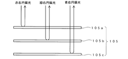
- FIG. 2 conceptually shows a cross-sectional structure of the visible light total reflection cholesteric liquid crystal layer 105.
- the visible light all-reflection cholesteric liquid crystal layer 105 includes three layers, a first cholesteric liquid crystal layer 105a, a second cholesteric liquid crystal layer 105b, and a third cholesteric liquid crystal layer 105c.
- these three layers are illustrated as if they are separated from each other, but actually, they are stacked and integrated.
- the cholesteric liquid crystal layer 105a is set to selectively reflect red (wavelength 650 ⁇ 50 nm) right-handed circularly polarized light
- the cholesteric liquid crystal layer 105b selectively selects green (wavelength 550 ⁇ 50 nm) right-handed circularly polarized light
- the cholesteric liquid crystal layer 105c is set to selectively reflect blue (wavelength 450 ⁇ 50 nm) right circularly polarized light.
- the first cholesteric liquid crystal layer 105a transmits the green and blue wavelength components regardless of the polarization state
- the second cholesteric liquid crystal 105b transmits the blue wavelength component regardless of the polarization state. Therefore, as shown in FIG. 2, red, green, and blue right-handed circularly polarized light is reflected in the upward direction of FIG. 2 from the visible light whole reflection cholesteric liquid crystal layer 105.
- the human eye sees a state equivalent to the case where the entire light in the visible light band is visually recognized. That is, optical characteristics equivalent to the case of circularly polarized light having a specific rotation (right circularly polarized light in the case of FIG.
- cholesteric liquid crystal layer 105 that reflects the entire visible light region
- three types of cholesteric liquid crystal having a characteristic of selectively reflecting red, green, and blue circularly polarized light in the same rotation direction are provided with a width of about 50 ⁇ m. It is also possible to adopt a configuration formed in a stripe shape, a lattice shape, or a dot shape.
- a cholesteric liquid crystal layer in which the pitch of the cholesteric liquid crystal is continuously varied like gradation and adjusted to reflect circularly polarized light having a wide wavelength band can be used as the visible light all-reflection cholesteric liquid crystal layer 105.
- the two colors or four colors or more combinations light in the visible light region when viewed by the human eye is also possible to create a state that appears to have been reflected.
- the thickness of the visible light all-reflection cholesteric liquid crystal layer 105 is preferably in the range of 0.5 ⁇ m to 10 ⁇ m, and more preferably in the range of 1 ⁇ m to 5 ⁇ m.
- a display pattern 106 is formed by printing on the lower surface (opposite to the observation surface) of the visible light total reflection cholesteric liquid crystal layer 105.
- the display pattern 106 is formed by an inkjet method.
- the contents of the display pattern 106 are characters, various patterns, codes, and the like.
- the code display content constituted by one or more selected from a bar code, a two-dimensional code, an OCR code, a hologram code, and a color code can be used.
- the printing method is not limited to the inkjet method, and other printing methods such as an offset printing method can be used.
- the display pattern 106 may be formed by providing the display pattern 106 on a base film such as a resin film and transferring the display pattern 106 to the entire visible light reflection cholesteric liquid crystal layer 105. It is also possible to construct a holographic display pattern 106.
- the adhesive layer 107 is disposed in contact with the display pattern 106.
- the adhesive layer 107 is an adhesive layer and is used when the identification medium 100 is attached to an object.
- a separator 108 which is a release paper, is attached to the back surface of the adhesive layer 107.
- the separator 108 is peeled off from the adhesive layer 107 and the adhesive layer 107 is brought into contact with the object.
- the identification medium 100 is fixed to the object by the adhesive force of the adhesive 107.
- the color scheme is set so that the display pattern 106 and the adhesive layer 107 look different colors. This is to make it easy to recognize the image of the display pattern 106.
- FIG. 1B shows an identification medium 100 ′ that is a modification of the identification medium 100.
- the identification medium 100 ′ includes, from the observation side, a hard coat layer 101a that functions as a protective layer, a cholesteric liquid crystal layer 102, a COP (cycloolefin polymer) layer 104, a visible light total reflection cholesteric liquid crystal layer 105, a display pattern 106, The adhesive layer 107 and the separator 108 are stacked.
- the hard coat layer 101a is a coat layer made of an acrylic resin, a urethane resin, or the like, and is a resin layer that protects the surface on the observation surface side of the cholesteric liquid crystal layer 102.
- the hard coat layer 101a is also selected so that it transmits visible light and does not disturb the polarization state of the transmitted light.
- the COP layer 104 is composed of a film of a cycloolefin polymer, and functions as a base material for the cholesteric liquid crystal layer 102 and the visible light all-reflection cholesteric liquid crystal layer 105.
- the cycloolefin polymer film constituting the COP layer 104 has a property of transmitting visible light and has a property of not disturbing the state of polarization of the transmitted visible light.
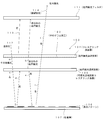
- FIG. 3 conceptually shows a state in which the identification medium 100 is observed through the left circular polarization filter 111.
- “right” indicates right circularly polarized light
- “left” indicates left circularly polarized light
- “other polarized light” is specified. It is a polarization component other than the right-handed circularly polarized light at the center wavelength.
- the cholesteric liquid crystal layer 102 selectively reflects the red right circularly polarized light 113.
- the selectively reflected red right circularly polarized light 113 is blocked by the left circular polarizing filter 111 and does not reach the observer side.
- right circularly polarized light other than red and mainly left circularly polarized light pass through the cholesteric liquid crystal layer 102 from the top to the bottom of the figure.
- the transmitted light is shown at a Other polarization.
- polarized light a is incident on the visible light all-reflection cholesteric liquid crystal layer 105, and the right circularly polarized light of the symbol b is reflected upward in the figure.
- This right circularly polarized light b is right circularly polarized light other than red, is blocked by the left circularly polarized light filter 111, and does not reach the observer.
- the left circularly polarized light (symbol “c”) included in the other polarized light “a” is transmitted through the visible light entire reflection cholesteric liquid crystal layer 105, reaches the display pattern 106, and is reflected there. At this time, the turning direction is reversed and reflected as right circularly polarized light d.
- the identification medium 100 when the identification medium 100 is observed through the left circular polarizing filter, the reflected light from the cholesteric liquid crystal layer 102 cannot be observed. That is, the hologram resulting from the hologram processing 103 cannot be observed.
- the image of the display pattern 106 can be visually recognized.
- an image recognition means using a camera that is, in image recognition using a camera, when imaging is performed through the left circular polarization filter 111, the hologram resulting from the hologram processing 103 is not acquired as an image, and the display of the display pattern 106 is acquired electronically as an image. Is done.
- a polarization component that can be transmitted through the visible light all-reflection cholesteric liquid crystal layer 105 is generated even when the polarization state is disturbed.
- This light passes through the cholesteric liquid crystal layer 102 and the left circularly polarizing filter 111 and is visually recognized by an observer.
- This light has the same image content as the observed light 114 and contributes to increasing the amount of the observed light 114.
- FIG. 4 shows a case where the identification medium 100 is observed through the right circular polarization filter 115.
- the behavior of light rays in the identification medium 100 is the same as in FIG.
- the red right circularly polarized light 113 selectively reflected from the cholesteric liquid crystal layer 102 passes through the right circular polarizing filter 115 and is observed by the observer as the observation light 116. Therefore, a hologram image resulting from the hologram processing 103 can be observed through the right circular polarization filter 115.
- the light mainly composed of left circularly polarized light reflected from the display pattern 106 and transmitted through the cholesteric liquid crystal layer 102 in the upward direction in the figure is blocked by the right circularly polarizing filter 115 and cannot be observed. That is, when the identification medium 100 is viewed through the right circular polarization filter 115, the display pattern 106 cannot be visually recognized. Thus, when the identification medium 100 is viewed through the right circular polarization filter 115, the display pattern 106 cannot be visually recognized, while the hologram based on the hologram processing 103 applied to the cholesteric liquid crystal layer 102 can be clearly viewed.
- the identification medium 100 is observed through the left circular polarization filter of FIG. 3, only the display pattern 106 is visible. At this time, reflection is repeatedly performed on the lower surface side of the entire visible light reflection cholesteric liquid crystal layer 105, and reflected light is generated to increase the intensity of the observed light 114. Thereby, the brightness of the display pattern 106 becomes high.
- the display pattern 106 when viewed through the right circular polarizing filter 115, the display pattern 106 is not visible, and the hologram resulting from the hologram processing 103 of the cholesteric liquid crystal layer 102 is selectively visible.
- FIG. 5 is a schematic diagram showing an example of the appearance when the identification medium 100 is observed by switching the above-described circular polarizing filter.
- “GENUINE” is a print pattern of the display pattern 106
- “Security” is a hologram image resulting from the hologram processing 103.
- FIG. 5A shows the contents of an image observed when the identification medium 100 is observed through the left circular polarization filter 111 shown in FIG.
- the display pattern 106 “GENUINE” is selectively observed clearly.
- the hologram “Security” resulting from the hologram processing 103 of the cholesteric liquid crystal layer 102 cannot be seen.
- FIG. 5B shows the contents of an image observed when the identification medium 100 is observed through the right circular polarization filter 115 shown in FIG.
- the hologram “Security” resulting from the hologram processing 103 is selectively observed.
- the display pattern 106 “GENUINE” is not visible.
- FIG. 5C shows the contents of the image when the identification medium 100 is directly observed.
- the hologram “Security” resulting from the hologram processing 103 and the display pattern “GENUINE” are simultaneously observed.
- a protective layer 101 is formed on a base film (not shown), and a cholesteric liquid crystal layer 102 is further grown thereon. Then, hologram processing 103 by embossing is performed on the exposed surface of the cholesteric liquid crystal layer 102.
- Each of 105c is formed individually.
- the individually formed first cholesteric liquid crystal layer 105a, second cholesteric liquid crystal layer 105b, and third cholesteric liquid crystal layer 105c are stacked on the exposed surface of the cholesteric liquid crystal layer 102, and fixed with an adhesive.
- a display pattern 106 is formed on the back side of the exposed visible light all-reflection cholesteric liquid crystal layer 105 by an inkjet method or the like.
- the adhesive layer 107 is provided on the exposed surface of the visible light all-reflection cholesteric liquid crystal layer 105, and the separator 108 is attached to the exposed surface of the adhesive layer 107, whereby the medium 100 illustrated in FIG.
- a hard coat layer 101a is formed on a resin film (not shown) such as a PET film, and further a cholesteric liquid crystal layer 102 is formed thereon, Hologram processing 103 is performed. This is transferred to the COP layer 104, and a resin film (not shown) is peeled off to obtain a laminate of the COP layer 104 and the cholesteric liquid crystal layer 102.
- the visible light all-reflection cholesteric liquid crystal layer 105 is obtained by the method described above, and is adhered to the exposed surface of the COP layer 104.
- the identification medium 100 ′ is manufactured through the same process as the identification medium 100.
- the amount of reflected light from the display pattern 106 can be increased. In other words, since the reflected light from the display pattern 106 can be efficiently taken out of the identification medium 100, the amount of reflected light from the display pattern 106 can be increased. For this reason, the display pattern 106 looks brighter and the display pattern 106 looks clearer than when the circularly polarizing filter is used.
- the identification medium 100 ′ having the structure shown in FIG. 1B has an advantage that unauthorized reuse is difficult. That is, the cycloolefin polymer constituting the COP layer 104 has a chemical property that is very easy to deteriorate when it comes into contact with hydrocarbon solvents such as gasoline, kerosene, thinner, benzine, etc. It has a physical property that tends to cause breakage and wrinkles when a peeling force is applied.
- the structure in which the COP layer is sandwiched between the cholesteric liquid crystal layer 102 and the visible light all-reflective cholesteric liquid crystal layer 105 may be used when the identification medium 100 is illegally peeled off using a solvent, When the identification medium 100 is peeled off from the object, the layer structure of the identification medium 100 is destroyed and cannot be reused. This property is useful for preventing or making unauthorized reuse of the identification medium 100 difficult.
- the cycloolefin polymer constituting the COP layer 104 is inexpensive, but has physical properties such as streaks and cracks caused by physical contact from the outside (for example, by touching with the hand). Have. When this phenomenon occurs, there arises a problem that it is visually recognized.
- the COP layer 104 is sandwiched between the cholesteric liquid crystal layer 102 and the visible light all-reflection cholesteric liquid crystal layer 105 from the front and back. From the outside, and the problem that the above-described streaks and cracks occur in the COP layer 104 does not occur.
- FIG. 6A shows an identification medium 200 .
- the identification medium 200 has a structure in which a birefringent layer 110 is arranged between the visible light all-reflection cholesteric liquid crystal layer 105 and the display pattern 106 in the identification medium 100 of FIG.
- FIG. 6B shows an identification medium 200 ′ having a structure in which the COP layer 104 is sandwiched between the cholesteric liquid crystal layer 102 and the visible light entire reflection cholesteric liquid crystal layer 105 in the identification medium 200 as a modification. ing. Since the identification media 200 and 200 ′ are the same except for the COP layer 104, the identification media 200 in FIG. 6A will be described below.
- the birefringent layer 110 is incident on the visible light all-reflection cholesteric liquid crystal layer 105 from the observation surface side (upper side in FIG. 1) and passes through the visible light all-reflection cholesteric liquid crystal layer 105 (in this case, mainly left circularly polarized light). Component) and the polarization state of the reflected light from the display pattern 106 are disturbed. That is, the birefringence effect acts to disturb the polarization state of transmitted light. By disturbing the polarization state, a light component that can be transmitted through the visible light all-reflection cholesteric liquid crystal layer 105 from the bottom to the top in FIG. 3 is generated, and the reflected light from the display pattern 106 that is transmitted through the left circular polarization filter 111.
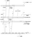
- FIG. 7 conceptually shows a state in which the identification medium 200 of FIG. 6 is observed through the left circular polarization filter 111.
- FIG. 7 what is described as "right” is the right circularly polarized light, what is described as “left” is the left circularly polarized light, that is described as “other polarization” specific
- a polarization component other than the right-handed circularly polarized light having the center wavelength and described as “others” is a light state in which the polarization state is disturbed and cannot be said to be a specific polarization state.
- the natural light entering the discrimination medium 200 the cholesteric liquid crystal layer 102 selectively reflects the red right circularly polarized light 113.
- the selectively reflected red right circularly polarized light 113 is blocked by the left circular polarizing filter 111 and does not reach the observer side.
- right circularly polarized light other than red and mainly left circularly polarized light pass through the cholesteric liquid crystal layer 102 from the top to the bottom of the figure.
- the transmitted light is shown at a Other polarization.
- polarized light a is incident on the visible light all-reflection cholesteric liquid crystal layer 105, and the right circularly polarized light of the symbol b is reflected upward in the figure.
- the right circularly polarized light with the symbol b is blocked by the left circular polarizing filter 111 and does not reach the observer.
- polarized light (symbol c) other than right circularly polarized light included in the polarized light a is incident on the birefringent layer 110, and the state of polarized light is disturbed by the birefringent effect. In this way, the light beam d in which the polarization state indicated by “others” is disturbed is incident on the display pattern 106 and reflected there.
- This reflected light is transmitted again through the birefringent layer 110 from the bottom to the top of the figure, and the state of polarization is further disturbed, and is incident on the lower surface side of the visible-light entire-reflection cholesteric liquid crystal layer 105 as a light beam with the symbol e.
- the light beam indicated by symbol e has a disordered polarization state and includes a left circularly polarized light component that can be transmitted through the visible light total reflection cholesteric liquid crystal layer 105.
- the component of the left circularly polarized light generated by the disorder of the changed state is transmitted through the visible light total reflection cholesteric liquid crystal layer 105 as the left circularly polarized light indicated by the symbol g.
- the left circularly polarized light indicated by the symbol g also passes through the cholesteric 102, reaches the left circularly polarized filter 111, passes therethrough, and is observed as the observed light 114a.
- the right circularly polarized light component in the light beam of the symbol e is reflected by the visible light all-reflection cholesteric liquid crystal layer 105 as the right circularly polarized light f and enters the birefringent layer 110.
- the birefringent layer 110 the right circularly polarized light f is disturbed in the polarization state and reflected on the display surface 106 as a light beam indicated by a symbol h.
- Reflected light j is generated by this reflection, and the reflected light j is further disturbed in the polarization state in the process of passing through the birefringent layer 110, and is incident on the lower surface of the visible light total reflection cholesteric liquid crystal layer 105 as a light beam indicated by a symbol k. To do.
- the polarization state of the light beam with the symbol k is also disordered, and the component of the left circularly polarized light that can be transmitted through the visible light all-reflection cholesteric liquid crystal layer 105 is the left circularly polarized light m. Then, the visible light entire reflection cholesteric liquid crystal layer 105 is transmitted upward in the figure.
- the right circularly polarized light indicated by reference numeral 1 included in the reference numeral k is reflected again in the direction of the display pattern 106.
- the left circularly polarized light m passes through the cholesteric liquid crystal layer 102 and further passes through the left circularly polarized filter 111 and is visually recognized by the observer as the observed light 114b.
- Right circular polarization l the state of polarization is disturbed in the course of passing through the birefringent layer 110, via label f ⁇ h ⁇ j ⁇ k similar pathway, the observed light part of the component as a left-circularly polarized light q 114c, and the component of the right circularly polarized light generated by the polarization disturbance is reflected again to the display pattern 106 side as the right circularly polarized light p.
- Left-hand circularly polarized light 114a, 114b, and 114c is reflected light from the display pattern 106 and includes image information of the display pattern 106. Further, the light is transmitted without being reflected or diffracted by the hologram of the cholesteric liquid crystal layer 102, and does not include hologram image information resulting from the hologram processing 103. For this reason, the display pattern 106 looks clear and the hologram of the cholesteric liquid crystal layer 102 cannot be seen. In addition, the images of the display pattern 106 are observed more brightly and clearly by combining the light to be observed 114a, 114b, and 114c. This effect is also obtained for the light beam with the sign p.
- FIG. 8 shows a case where the identification medium 200 is observed through the right circular polarization filter 115.
- the behavior of light inside the identification medium 200 is the same as in FIG.
- the left circularly polarized light reflected from the identification medium 200 is blocked by the right circular polarizing filter 115 and is not observed.
- the right circularly polarized light 113 reflected from the cholesteric liquid crystal layer 102 passes through the right circularly polarized filter 115 and is observed by the observer as the observed light 117.
- the display pattern 106 is not observed, and a hologram based on the hologram processing 103 is selectively observed.
- the identification medium 200 when the identification medium 200 is observed through the left circular polarizing filter, only the display pattern 106 is visible. At this time, reflection is repeatedly performed on the lower surface side of the visible light total reflection cholesteric liquid crystal layer 105, and further, there is generated reflected light that increases the intensity of the observed light 114 a by the birefringence effect in the birefringent layer 110.
- the observed contents described above are the same whether the circularly polarizing filters 111 and 114 are separated from the identification medium or in close contact with the identification medium. Moreover, cholesteric liquid crystal, changing the viewing angle, but the color shifting effect of color is shifted to the shorter wavelength side is observed, even in the identification medium 200 and 200 ', by changing the viewing angle (e.g., the identification medium thing) tilting, can be observed color shift.
- FIG. 9A shows an identification medium 300 of the embodiment.
- the identification medium 300 has a structure in which a protective layer 101, a cholesteric liquid crystal layer 102 on which a hologram processing 103 has been performed, a visible light entire reflection cholesteric liquid crystal layer 105, and an adhesive layer 601 are arranged from the observation side.
- FIG. 9 shows an identification object (article) 603 on which a display pattern 602 is further formed.
- the reference numerals common to FIG. 1 are the same as those described in relation to FIG. In this example, a state where the identification medium 300 is attached to the object 603 by the adhesive force of the adhesive layer 601 is shown.
- FIG. 9 shows an identification medium 300 of the embodiment.
- the identification medium 300 has a structure in which a protective layer 101, a cholesteric liquid crystal layer 102 on which a hologram processing 103 has been performed, a visible light entire reflection cholesteric liquid crystal layer 105, and an adhesive layer 601 are arranged from the observation side.
- FIG. 9B shows an identification medium 300 ′ having a structure in which a COP layer 104 is interposed between the cholesteric liquid crystal layer 102 and the visible light whole-reflection cholesteric liquid crystal layer 105 in the identification medium 300 shown in FIG. 9A. It is shown.
- the adhesive layer 601 is an optically transparent adhesive.
- the display pattern 602 is a print pattern formed on the surface of the object 601, and is a code display such as various patterns, characters, logos, patterns, and barcodes.
- the optical property of the identification medium 300 is the same as that of the identification medium 100 of FIG.
- the identification medium 300 differs from the identification medium 100 of FIG. 1 in that the identification medium 100 includes a display pattern 106 that is a basis of an image used for identification, whereas the identification medium 300 uses an image used for identification as an image used for identification.
- the display pattern 602 on the object 603 side is used.
- a separator (release paper) (not shown) is attached to the back side of the adhesive layer 601 in a state where it is not attached to the object, that is, in a state where the identification medium 300 is not used. At the time of use, this separator is peeled off from the back surface of the adhesive layer 601, and the identification medium 300 is attached to the object by the adhesive function of the adhesive layer 601. An example of this state is shown in FIG. Further, in the structure shown in FIG. 9, it is possible to provide a birefringent layer on the lower surface side of the visible light all-reflection cholesteric liquid crystal layer 105 and obtain an optical function similar to that described with reference to FIGS. .
- FIG. 10 shows an identification medium 400.
- the identification medium 400 has a structure in which a protective layer 101, an optically anisotropic layer 301, a visible light all-reflection cholesteric liquid crystal layer 105, an adhesive layer 107, and a separator 108 are laminated from the observation side surface.
- a protective layer 101 an optically anisotropic layer 301, a visible light all-reflection cholesteric liquid crystal layer 105, an adhesive layer 107, and a separator 108 are laminated from the observation side surface.
- the same reference numerals as those in FIG. 1 are the same as those in FIG.
- the optically anisotropic layer 301 is made of an oriented polymer material having birefringence, and is made of a material that undergoes a polymerization reaction of the polymer when exposed to light and whose orientation state is determined.
- the polymer in the optically anisotropic layer has an unreacted reactive group. Unreacted reactive groups react upon exposure to cause cross-linking of the polymer chains, and the degree of cross-linking of the polymer chains varies depending on exposure under different exposure conditions. As a result, the retardation value changes, resulting in a birefringence pattern. It is formed.
- the optically anisotropic layer 301 may have a retardation of 5 nm or more at 20 ° C., preferably 10 nm or more and 10,000 nm or less, and most preferably 20 nm or more and 2000 nm or less.
- a solution containing a liquid crystal compound having at least one reactive group is applied and dried to form a liquid crystal phase, and then irradiated with ionizing radiation to be polymerized and fixed. Adopt the method to do.
- This method is described in JP2009-175208A.
- a method of stretching a layer in which a monomer having at least two or more reactive groups is polymerized and immobilized, a reactive group is formed using a coupling agent in a layer made of a polymer.
- the optically anisotropic layer of the present invention may be formed by transfer.
- the thickness of the optically anisotropic layer 301 is preferably 0.1 to 20 ⁇ m, and more preferably 0.5 to 10 ⁇ m.
- a composition containing a liquid crystal compound (for example, a coating solution) is applied onto an easily peelable layer that has been subjected to an alignment treatment.
- a liquid crystal compound containing a rod-like liquid crystal, a horizontal alignment agent, a cationic photopolymerization initiator, a polymerization controller, and methyl ethyl ketone is used.
- this orientation state is fixed by irradiation of ionizing radiation.
- the alignment state of the aligned liquid crystal compound is fixed by a photopolymerization reaction.
- the irradiation energy for light irradiation is selected from 25 to 800 mJ / cm 2 .
- As the irradiation wavelength ultraviolet light having a peak at 250 to 450 nm is used.
- the region D is a simple light transmission layer that does not emit light and does not produce a birefringence effect.
- the above phase difference is adjusted by changing the light amount (exposure amount) of the irradiated light. Thereafter, by applying heat treatment at a temperature of 200 ° C., the state of fixation of the alignment state according to the amount of light irradiated is determined, thereby obtaining the optically anisotropic layer 301 partially different in birefringence state. . If light is not applied, the orientation state is disturbed during heat treatment, and the birefringence of the region disappears (a simple light transmission layer).
- the above heat treatment can be performed at a temperature selected from the range of 50 ° C to 400 ° C.
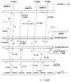
- an optically anisotropic layer 301 is obtained in which there is a difference in the refractive index in the orthogonal direction in the plane, and the state of the difference is different in the regions A, B, and C shown in FIG.
- the phase difference generated in these regions is set so that the regions A, B, and C appear to have different colors during observation using the circular polarizing filter.
- the region D is formed as a simple light transmission region having no refractive index anisotropy.
- the optically anisotropic layer 301 When the optically anisotropic layer 301 is obtained, it is peeled off from an easy peeling layer (not shown) and fixed to the protective layer 101. Thereafter, lamination with the visible light all-reflection cholesteric liquid crystal layer 105, formation of the adhesive layer 107, and attachment of the separator 108 are performed to obtain the identification medium 400 shown in FIG.
- the fixing of the identification medium 400 to the object is performed by removing the separator 108 and bringing the adhesive layer 107 into contact with the object. This is the same as the identification medium 100 of FIG. Note that the turning direction of the circularly polarized light selectively reflected by the visible light all-reflection cholesteric liquid crystal layer 105 is not limited to the right turn but may be the left turn.
- the reason why the reflected light from the areas A, B, and C looks different colors is as follows.
- the phase difference component of the polarization orthogonal with an optical anisotropic layer within 301 occurs, since this occurs the phase difference is wavelength dependent, when focusing on a certain polarization components, optical A color centered on the wavelength corresponding to the phase difference generated in the anisotropic layer 301 can be seen. For this reason, different colors are observed depending on the difference in the generated phase difference.
- the regions A, B, and C are set to have different phase differences, the regions A, B, and C have different colors in the observation through the circular polarization filter. appear.
- the regions A, B, and C appear to have different colors from those when the right circular polarization filter is used. This is because the polarization component extracted by the circular polarization filter is different from the case where the right circular polarization filter is used. Also in this case, each of the regions A, B, and C looks different colors. Further, since the right circularly polarized reflected light from the region D is blocked by the left circular polarizing filter, the reflected light from the visible light all-reflection cholesteric liquid crystal layer 105 is not visible, and the background of the visible light all-reflection cholesteric liquid crystal layer 105 is visible. The adhesive layer 107 is visible. Here, if the adhesive layer 107 is colored, the color is visible in the region D, and if the adhesive layer 107 is transparent, the surface of the lower layer of the adhesive layer 107 is visible in the region D.
- the optically anisotropic layer including a plurality of regions having different optical anisotropy states and the visible light total reflection cholesteric liquid crystal layer are arranged from the observed side. It has a structure.
- the identification medium 500 When the identification medium 500 is observed from the upper direction of the drawing through the right circular polarizing filter, for example, red right circular polarized light reflected from the cholesteric liquid crystal layer 102 is observed. For this reason, the hologram resulting from the hologram processing 103 is observed.
- the identification medium 500 When the identification medium 500 is observed through the left circular polarizing filter, the reflected light from the cholesteric liquid crystal layer 102 cannot be observed.
- the right circularly polarized light reflected from the cholesteric liquid crystal layer 105 that reflects the entire visible light region is inverted by the ⁇ / 2 plate 401 to become left circularly polarized light, and thus passes through the cholesteric liquid crystal layer 102 as it is.
- Reflected light from the reflective cholesteric liquid crystal layer 105 can be observed. Since this reflected light is left circularly polarized light and is observed as light in the entire visible light range, for example, reflected light having a metallic luster is observed in a state where the hologram of the cholesteric liquid crystal 102 is not visible.
- the ⁇ / 2 plate 401 can be omitted when the rotation direction of the circularly polarized light reflected from the visible light whole reflection cholesteric liquid crystal layer 105 is set to the left rotation. It is also possible to selective reflection wavelength of the cholesteric liquid crystal layer 102 and the other color other than red, also be also set to the turning direction of the circularly polarized light is selectively reflected and left turn.
- FIG. 12 shows, from the observed side, a cholesteric liquid crystal layer that has been subjected to hologram processing, a ⁇ / 2 plate, and a visible light that selectively reflects circularly polarized light in the same turning direction as the cholesteric liquid crystal layer. and an optical entire reflecting cholesteric liquid crystal layer.
- the turning direction of the circularly polarized light reflected from the visible light all-reflection cholesteric liquid crystal layer is opposite to that of the cholesteric liquid crystal layer.
- the present invention can be used for a technique for identifying authenticity.
Landscapes
- Physics & Mathematics (AREA)
- Chemical & Material Sciences (AREA)
- Engineering & Computer Science (AREA)
- General Physics & Mathematics (AREA)
- Nonlinear Science (AREA)
- Crystallography & Structural Chemistry (AREA)
- Theoretical Computer Science (AREA)
- Optics & Photonics (AREA)
- Mathematical Physics (AREA)
- Computer Security & Cryptography (AREA)
- Toxicology (AREA)
- Health & Medical Sciences (AREA)
- General Health & Medical Sciences (AREA)
- Manufacturing & Machinery (AREA)
- General Chemical & Material Sciences (AREA)
- Chemical Kinetics & Catalysis (AREA)
- Dispersion Chemistry (AREA)
- Polarising Elements (AREA)
- Credit Cards Or The Like (AREA)
- Holo Graphy (AREA)
- Business, Economics & Management (AREA)
- Accounting & Taxation (AREA)
- Finance (AREA)
Abstract
低コストで得られる構造で明瞭な画像の切り替わりを観察でできる識別媒体を提供する。観察が行われる側から、ホログラム加工が施され、特定中心波長の特定旋回方向の円偏光を選択的に反射するコレステリック液晶層102と、可視光全域の光を反射する場合と等価な反射特性を有し、コレステリック液晶層102から反射される円偏光と同じ旋回方向の円偏光を反射する可視光全域反射コレステリック液晶層105と、特定の表示内容とされた表示パターン106とが配置された構造とする。
Description
本発明は、観察内容の明瞭な切り替わりを観察できる識別媒体に関する。
特許文献1には、ホログラム加工が施され、右円偏光を選択反射する第1のコレステリック液晶層と、ホログラム加工が施され、左円偏光を選択反射する第2のコレステリック液晶層とを積層した構造とすることで、左右の円偏光フィルタを用いた選択的な観察において、2つのホログラム絵柄の切り替わりが観察可能な構造について記載されている。
特許文献2には、ホログラム加工を施したコレステリック液晶層と印刷層を組み合わせることで、円偏光フィルタを介して観察した場合に、ホログラム絵柄と印刷絵柄の切り替わりを観察できる構成が記載されている。
特許文献1に記載されている技術では、ホログラム絵柄の切り替わりを観察することが可能であるが、2層のコレステリック液晶層のそれぞれに対してホログラム加工を施さなくてはならず、製造コストが高くなる。特許文献2に記載されている技術では、コレステリック液晶層からの反射光を透過する円偏光フィルタを用いての観察において、ホログラムと同時に下地の印刷層が見え、明瞭な絵柄の切り替わりという点で課題がある。
このような背景において、本発明は、低コストで得られる構造で明瞭な画像の切り替わりを観察でできる識別媒体を提供することを目的とする。
請求項1の発明は、観察が行われる側から、ホログラム加工が施され、特定中心波長の特定旋回方向の円偏光を選択的に反射する第1のコレステリック液晶層と、可視光全域の光を反射する反射特性または可視光全域の光を反射する場合と等価な反射特性を有し、前記第1のコレステリック液晶層から反射される円偏光と同じ旋回方向の円偏光を反射する第2のコレステリック液晶層と、特定の表示内容とされた表示パターンと配置された構造を有することを特徴とする識別媒体である。
請求項1に記載の発明によれば、特定の旋回であり、且つ、可視光全域の波長分布を持っている場合と等価な円偏光を選択的に透過する第2のコレステリック液晶層の性質を利用することで、第1のコレステリック液晶層からの選択反射光を遮断する円偏光フィルタを介した観察において、第1のコレステリック液晶層のホログラムに邪魔されずに表示パターンの表示内容を鮮明に観察することができる。この際、表示パターンから反射され、第2のコレステリック液晶層を透過できず、その下面で再度表示パターンの方向に反射された光が、反射を繰り返すことで第2のコレステリック液晶層を透過可能な偏光となり、表示パターンを認識するための光として識別媒体から出射する。このため、円偏光フィルタ越しに表示パターンを選択的に視認する際の視認性が高くなる。
請求項2に記載の発明は、請求項1に記載の発明において、前記第2のコレステリック液晶層と前記表示パターンとの間に屈折率異方性を有する光透過層が設けられていることを特徴とする。
請求項3に記載の発明は、観察が行われる側から、ホログラム加工が施され、特定中心波長の特定旋回方向の円偏光を選択的に反射する第1のコレステリック液晶層と、可視光全域の光を反射する反射特性または可視光全域の光を反射する場合と等価な反射特性を有し、前記第1のコレステリック液晶層から反射される円偏光と同じ旋回方向の円偏光を反射する第2のコレステリック液晶層と、光透過性を有する粘着層とを備えることを特徴とする識別媒体である。
請求項3に記載の発明によれば、粘着層が光透過性(可視光を透過する性質)であるので、対象物に貼り付けた状態において、対象物の表面の表示を利用しての請求項1の発明の場合と同様な光学機能を得ることができる。
請求項4に記載の発明は、請求項1~3のいずれか一項に記載の発明において、前記第1のコレステリック液晶層が一方の面に接触し、前記第2のコレステリック液晶層が他方の面に接触したシクロオレフィンポリマーの層を備えることを特徴とする。
シクロオレフィンポリマーは、安価であり、またガソリン、灯油、シンナー、ベンジン等の炭化水素系の溶剤に触れると非常に劣化しやすい化学的な性質を有し、更に溶剤に触れた状態で引き剥がすような力を加えた際に破断や皴が生じ易い物理的な性質を有している。このため、請求項3に記載の発明を採用することで、識別媒体を不正に剥がそうとした場合や、強制的に対象物から剥がそうとした場合に、識別媒体の層構造が破壊され再利用ができなくなる構造とできる。この性質は、識別媒体100の不正な再利用を防止あるいは困難にする上で有用となる。
また、シクロオレフィンポリマーは、上述した優位性があるが、外部からの物理的な接触によって(例えば、手で触ることで)、筋が寄ったりクラックが生じたりする物理的な性質を有している。この現象が生じると、光学的にそれが視認される問題が生じる。請求項4に記載の発明によれば、シクロオレフィンポリマーの層が表裏からコレステリック液晶層および可視光全域反射コレステリック液晶層によって挟まれた構造とされているので、貼り付け作業等においてシクロオレフィンポリマーの層への外部からの接触が防止され、上述した筋やクラックが生じる問題が発生しない。
本発明によれば、低コストで得られる構造で明瞭な画像の切り替わりを観察できる識別媒体が得られる。
100…識別媒体、101…保護層、102…コレステリック液晶層、103…ホログラム加工、104…COP(シクロオレフィンポリマー)層、105…可視光全域反射コレステリック液晶層、105a…コレステリック液晶層、105b…コレステリック液晶層、105c…コレステリック液晶層、106…表示パターン、107…粘着層、108…セパレータ、109…対象物、110…複屈折層、200…識別媒体、300…識別媒体、301…光学異方性層、400…識別媒体、500…識別媒体。
(1)第1の実施形態
(構成)
図1(A)には、実施形態の識別媒体100が示されている。識別媒体100は、観察が行われる側から、保護層101、コレステリック液晶層102、可視光全域反射コレステリック液晶層105、表示パターン106、粘着層107、セパレータ108と積層された構造を有する。保護層101は、観察面を保護するもので、可視光に対する光透過性を有し、透過する光の偏光状態を乱さない材質により構成された薄い膜である。保護層101を構成する材質としては、トリアセチルセルロース、アクリル、シクロオレフィン等が挙げられる。特にシクロオレフィンは、耐油性が劣るため、シクロオレフィンを保護層101として用いた場合、対象物に貼り付けた後に溶剤やオイル等を滴下して識別媒体100を剥がそうとした際に、保護層101が崩壊し、識別媒体100を不正に剥がしての再利用ができなくなる優位性が得られる。
コレステリック液晶層102は、赤の右旋回の円偏光を選択的に反射する設定とされ、観察面側に対して反対側の面(図1の場合下面)にエンボス型を押し付けることで形成したホログラム加工103が施されている。コレステリック液晶層102からの反射光を観察した場合、このホログラム加工103に基づくホログラム像が観察される。コレステリック液晶層102が選択反射する円偏光の旋回方向は、左旋回でもよい。ただし、その旋回方向は、後述する可視光全域反射コレステリック液晶層105が選択反射する円偏光の旋回方向と同じになるようにする。また、コレステリック液晶層102が選択反射する円偏光の中心波長も利用目的や視認機能に合わせて、緑等の他のものを選択することができる。
可視光全域反射コレステリック液晶層105は、右円偏光を選択的に反射し、且つ、自然光が当たっている状態において、選択反射された円偏光を観察した際にそれが可視光全域の光に見える光学的な性質を有している。つまり、特定の波長帯域を選択反射するのではなく、入射した可視光帯域の全ての波長を反射する特性、あるいは入射した可視光帯域の全ての波長を反射する場合と等価な反射特性を有している。なお、便宜上可視光全帯域と称しているが、可視光の帯域の全ての成分を含んでいる場合に限定されず、その中の複数の波長ピークの組み合わせにより、人間が視認した際に可視光全域の波長を含む光に見える波長スペクトルを有した反射特性の場合も含まれる。
なお、コレステリック液晶層102から左円偏光が選択反射される設定とされている場合には、可視光全域反射コレステリック液晶層105からも左円偏光が選択反射されるように設定される。つまり、可視光全域反射コレステリック液晶層105が反射する円偏光の旋回方向は、コレステリック液晶層102が選択反射する円偏光の旋回方向と同じなるようにする。
以下、可視光全域反射コレステリック液晶層105について詳細に説明する。まず、通常のコレステリック液晶層では、特定旋回方向で、且つ、赤や緑といった特定の中心波長の円偏光を選択的に反射し、逆旋回方向の円偏光、直線偏光、および上記特定旋回方向の光であっても上記の中心波長以外の波長成分の円偏光は反射せずに透過する。これは、コレステリック液晶層のピッチの寸法により、選択反射される光の波長が決まっているからである。これに対して、可視光全域反射コレステリック液晶層105は、特定旋回方向の可視光帯域全体(あるいはそう見なせる波長スペクトル)の円偏光を選択的に反射する。もちろん、直線偏光および逆旋回方向の円偏光は透過する。この光学特性は、複数のピッチのコレステリック液晶層を複合化することで得られる。可視光全域コレステリック液晶については、例えば、特許第3373374号公報に記載されている。
以下、可視光全域反射コレステリック液晶層105の一例を説明する。図2には、可視光全域反射コレステリック液晶層105の断面構造が概念的に示されている。図2において、可視光全域反射コレステリック液晶層105は、第1のコレステリック液晶層105a、第2のコレステリック液晶層105b、第3のコレステリック液晶層105cの3層から構成されている。なお、図2では、これら3層が離れているかのように記載されているが、実際には、積層されて一体化されている。
ここで、コレステリック液晶層105aは、赤(波長650±50nm)の右円偏光を選択的に反射する設定とされ、コレステリック液晶層105bは、緑(波長550±50nm)の右円偏光を選択的に反射する設定とされ、コレステリック液晶層105cは、青(波長450±50nm)の右円偏光を選択的に反射する設定とされている。
この3層構造の可視光全域反射コレステリック液晶層105に自然光が図2の上の方向から入射する場合を考える。この場合、赤の右円偏光が第1のコレステリック液晶層105aから選択的に反射され、緑の右円偏光が第2のコレステリック液晶層105bから選択的に反射され、青の右円偏光が第3のコレステリック液晶層105cから選択的に反射される。この際、第1のコレステリック液晶層105aは、緑と青の波長成分をその偏光の状態に係らず透過し、第2のコレステリック液晶105bは、青の波長成分をその偏光の状態に係らず透過するので、図2に示すように、赤、緑、青の右円偏光が可視光全域反射コレステリック液晶層105から図2の上の方向に反射される。赤、緑、青の光を同時に観察すると、人間の目には、可視光帯域の光全域が視認される場合と等価な状態が視認されることになる。つまり、特定旋回の円偏光(図2の場合は右円偏光)であって、且つ、可視光の全帯域の光を選択反射する場合と等価な光学特性が得られる。この場合、目視での観察において、白色、鏡面、金属光沢色、あるいは白銀色(白っぽい金属光沢色)が観察される。これらの見た目の違いは、反射面の平滑性の違いによって生じる。例えば、反射面が粗面であれば、白色光が観察され、平滑性が高ければ鏡からのような反射光が観察され、反射面の平滑度が鏡面とはいえない程度である場合は、金属光沢色や銀白色が観察される。
可視光全域反射コレステリック液晶層105としては、図2に示す積層タイプの他に、赤、緑、青の同旋回方向の円偏光を選択反射する特性の3種類のコレステリック液晶を50μm程度の幅でストライプ状、格子状、ドット状に形成した構成を採用することも可能である。また、コレステリック液晶のピッチをグラデーションのように連続的に可変させ、幅をもった波長帯域の円偏光を反射する特性に調整したものを可視光全域反射コレステリック液晶層105として利用することもできる。
また、RGBではなく、2色あるいは4色以上の組み合わせによって、人間の目で見た際に可視光全域の光が反射されたかのように見える状態を作り出すことも可能である。勿論、可視光帯域全体を極力まんべんなくカバーする波長スペクトルの反射光が得られるようにし、実質的に可視光の全帯域が反射される特性とすることも可能である。なお、可視光全域反射コレステリック液晶層105の厚さは0.5μm~10μmの範囲、好ましくは1μm~5μmの範囲の値とすることが好ましい。
図1に戻り、可視光全域反射コレステリック液晶層105の下面(観察面と反対側)には、表示パターン106が印刷により形成されている。この例において、表示パターン106は、インクジェット法により形成されている。表示パターン106の内容は、文字、各種の絵柄、コード等である。コードとしては、バーコード、2次元コード、OCRコード、ホログラムコード、カラーコードから選ばれた一または複数により構成される表示内容を利用することができる。また、印刷方法は、インクジェット法に限定されず、オフセット印刷法等の他の印刷方法を用いることができる。また、樹脂フィルム等の基材フィルム上に表示パターン106を設け、それを可視光全域反射コレステリック液晶層105に転写する方法で表示パターン106を形成することもできる。また、表示パターン106をホログラムにより構成することもできる。
表示パターン106に接して、粘着層107が配置されている。粘着層107は、粘着剤の層であり、識別媒体100を対象物に貼り付ける際に利用される。粘着層107の裏面には、離型紙であるセパレータ108が貼り付けられている。識別媒体100を対象物に貼り付ける際には、セパレータ108を粘着層107から剥がし、粘着層107を対象物に接触させる。この粘着剤107の粘着力により、識別媒体100が対象物に固定される。なお、表示パターン106と粘着層107とは異なる色に見えるように配色を設定する。これは、表示パターン106の画像を認識し易くするためである。
図1(B)には、識別媒体100の変形例である識別媒体100’が示されている。識別媒体100’は、観察が行われる側から、保護層として機能するハードコート層101a、コレステリック液晶層102、COP(シクロオレフィンポリマー)層104、可視光全域反射コレステリック液晶層105、表示パターン106、粘着層107、セパレータ108と積層された構造を有する。ハードコート層101aは、アクリル樹脂やウレタン樹脂等によるコート層であり、コレステリック液晶層102の観察面側の表面を保護する樹脂の層である。ハードコート層101aも可視光を透過し、且つ、透過する光の偏光の状態を乱さないものが選択される。
COP層104は、シクロオレフィンポリマーをフィルム状にしたもので構成されており、コレステリック液晶層102および可視光全域反射コレステリック液晶層105の基材として機能する。COP層104を構成するシクロオレフィンポリマーのフィルムは、可視光を透過する性質を有し、また透過する可視光の偏光の状態を乱さない性質を有している。
(光学機能:左円偏光フィルタ越しの観察)
図3には、左円偏光フィルタ111を介して識別媒体100を観察している状態が概念的に示されている。なお、図3において、「右」と記載されているのが右円偏光であり、「左」と記載されているのが左円偏光であり、「その他偏光」と記載されているのが特定中心波長の右円偏光以外の偏光成分である。
図3には、左円偏光フィルタ111を介して識別媒体100を観察している状態が概念的に示されている。なお、図3において、「右」と記載されているのが右円偏光であり、「左」と記載されているのが左円偏光であり、「その他偏光」と記載されているのが特定中心波長の右円偏光以外の偏光成分である。
ここで、識別媒体100に自然光が入射したとする。この場合、コレステリック液晶層102は、赤の右円偏光113を選択反射する。この選択反射された赤の右円偏光113は、左円偏光フィルタ111で遮断され、観察者側には届かない。また、コレステリック液晶層102に入射した自然光のうち、赤以外の右円偏光および主に左円偏光がコレステリック液晶層102を図の上から下方向に向かって透過する。この透過光がその他偏光として符号aで示されている。
その他偏光aは、可視光全域反射コレステリック液晶層105に入射し、そこで符号bの右円偏光が図の上方向に反射される。この右円偏光bは、赤以外の右円偏光であり、左円偏光フィルタ111で遮断され、観察者には届かない。また、その他偏光aに含まれる主に左円偏光(符号c)が、可視光全域反射コレステリック液晶層105を透過し、表示パターン106に到達し、そこで反射される。この際、旋回方向が反転し、右円偏光dとして反射される。この右円偏光dは、可視光全域反射コレステリック液晶層105の下面で図の下方向に反射され、右円偏光eとして再度表示パターン106に入射する。右円偏光eは、表示パターン106で反射される際に旋回方向が反転し、左円偏光fとして反射される。左円偏光fは、可視光全域反射コレステリック液晶層105およびコレステリック液晶層102を透過し、左円偏光フィルタ111に入射し、そこを透過して被観察光114として観察者に届く。
こうして、左円偏光フィルタ越しに識別媒体100を観察した場合、コレステリック液晶層102からの反射光は観察できない。つまりホログラム加工103に起因するホログラムは観察できない。他方で、表示パターン106からの反射光は観察できるので、表示パターン106の画像を視認することができる。これは、カメラによる画像認識手段を用いた場合も同じである。つまり、カメラを用いた画像認識において、左円偏光フィルタ111を介した撮像を行った場合、ホログラム加工103に起因するホログラムが画像として取得されず、表示パターン106の表示が画像として電子的に取得される。
また、表示パターン106での光の反射が行われる際に、偏光状態の乱れが生じた場合でも、可視光全域反射コレステリック液晶層105を透過できる偏光成分が生じる。この光は、コレステリック液晶層102および左円偏光フィルタ111を透過し、観察者によって視認される。この光は、被観察光114と同じ画像内容を有しており、被観察光114の光量を大きくすることに寄与する。
(光学機能:右円偏光フィルタ越しの観察)
図4には、識別媒体100を右円偏光フィルタ115越しに観察する場合が示されている。図4において、識別媒体100における光線の振る舞いは、図3の場合と同じである。この場合、コレステリック液晶層102から選択反射される赤の右円偏光113は、右円偏光フィルタ115を透過し、被観察光116として観察者に観察される。したがって、ホログラム加工103に起因するホログラムの像を右円偏光フィルタ115越しに観察することができる。
図4には、識別媒体100を右円偏光フィルタ115越しに観察する場合が示されている。図4において、識別媒体100における光線の振る舞いは、図3の場合と同じである。この場合、コレステリック液晶層102から選択反射される赤の右円偏光113は、右円偏光フィルタ115を透過し、被観察光116として観察者に観察される。したがって、ホログラム加工103に起因するホログラムの像を右円偏光フィルタ115越しに観察することができる。
また、表示パターン106から反射され、コレステリック液晶層102を図の上方向に透過した左円偏光が主体の光は、右円偏光フィルタ115で遮断されるので観察できない。つまり、右円偏光フィルタ115越しに識別媒体100を見た場合、表示パターン106は視認できない。こうして、右円偏光フィルタ115越しに識別媒体100を見た場合、表示パターン106は視認できず、他方において、コレステリック液晶層102に施されたホログラム加工103に基づくホログラムが鮮明に視認できる。
以上説明したように、図3の左円偏光フィルタ越しに識別媒体100を観察した場合は、表示パターン106のみが見える。この際、可視光全域反射コレステリック液晶層105の下面側で繰り返し反射が行われ、被観察光114の強度を高める反射光の生成が行われる。これにより、表示パターン106の明度が高くなる。
また、図4に示すように、右円偏光フィルタ115を介して観察した場合、表示パターン106は見えず、コレステリック液晶層102のホログラム加工103に起因するホログラムが選択的に見える。
なお、識別媒体100を直視した場合は、反射される全ての偏光成分が同時に見えるので、コレステリック液晶層102のホログラムと表示パターン106とが同時に見える。
このように、左右の円偏光フィルタを切り替えての観察を行うことで、表示パターンとホログラムとを切り替えて観察することができる。この切り替わりは明瞭である。さらに直視した場合を加えて3種類のパターンを識別することできる。
図5は、上述した円偏光フィルタを切り替えて識別媒体100を観察した場合における見え方の一例を示す模式図である。図5において、「GENUINE」は、表示パターン106の印刷パターンであり、「Security」は、ホログラム加工103に起因するホログラムの画像である。
図5(A)には、図3に示す左円偏光フィルタ111を介して識別媒体100を観察した場合に観察される画像の内容が示されている。この場合、図3を参照して説明したように、表示パターン106「GENUINE」が選択的に鮮明に観察される。この際、コレステリック液晶層102のホログラム加工103に起因するホログラム「Security」は見えない。
図5(B)には、図4に示す右円偏光フィルタ115を介して識別媒体100を観察した場合に観察される画像の内容が示されている。この場合、図4を参照して説明したように、ホログラム加工103に起因するホログラム「Security」が選択的に観察される。この際、表示パターン106「GENUINE」は見えない。
図5(C)には、識別媒体100を直接観察した場合の画像の内容が示されている。この場合、ホログラム加工103に起因するホログラム「Security」と表示パターン106「GENUINE」とが同時に観察される。
以上の観察内容は、カメラによる画像認識手段を用いた場合も同じである。つまり、カメラを用いた画像認識において、左円偏光フィルタ111を介した撮像を行った場合、ホログラム加工103に起因するホログラム「Security」が画像として取得されず、表示パターン106「GENUINE」が画像として電子的に取得される。また、右円偏光フィルタ115を介した撮像を行った場合、ホログラム加工103に起因するホログラム「Security」が画像として取得され、表示パターン106「GENUINE」の画像が取得できない。また、円偏光フィルタを介さずにカメラによる撮像を行った場合、ホログラム「Security」と表示パターン106「GENUINE」の画像が重なった画像情報が取得される。
以上説明した観察される内容は、円偏光フィルタ111や114を識別媒体から離した場合であっても、識別媒体に密着させた場合であっても同じである。また、コレステリック液晶は、見る角度を変えると、色彩が短波長側にシフトするカラーシフト効果が観察されるが、識別媒体100および100’においても、見る角度を変えることで(例えば、識別媒体を傾けることで)、カラーシフトを観察することができる。また、図1(B)の識別媒体100’の光学機能は、図1(A)の識別媒体100の場合と同じであり、COP層104以外の構成が同じであるならば、観察される内容も同じである。
(製造方法)
以下、図1(A)の識別媒体100を得る工程の一例を説明する。まず、図示しない基材フィルム上に保護層101を形成し、更にその上にコレステリック液晶層102を成長させる。そして、コレステリック液晶層102の露出面に型押しによるホログラム加工103を施す。
以下、図1(A)の識別媒体100を得る工程の一例を説明する。まず、図示しない基材フィルム上に保護層101を形成し、更にその上にコレステリック液晶層102を成長させる。そして、コレステリック液晶層102の露出面に型押しによるホログラム加工103を施す。
他方において、図示しない他の基材フィルム上で、図2に示す可視光全域反射コレステリック液晶層105を構成する第1のコレステリック液晶層105a、第2のコレステリック液晶層105bおよび第3のコレステリック液晶層105cをそれぞれ個別に形成する。そして、個別に形成した第1のコレステリック液晶層105a、第2のコレステリック液晶層105bおよび第3のコレステリック液晶層105cをコレステリック液晶層102の露出面で積層し、接着剤によって固定する。次に露出した可視光全域反射コレステリック液晶層105の裏面側にインクジェット法等により、表示パターン106を形成する。次に、可視光全域反射コレステリック液晶層105の露出面に粘着層107を設け、さらに粘着層107の露出面にセパレータ108を貼り付けることで、図1(A)に示す媒体100を得る。
図1(B)の識別媒体100’を製造する場合、まず、図示しないPETフィルム等の樹脂フィルム上にハードコート層101aを形成し、更にその上にコレステリック液晶層102を形成して、そこにホログラム加工103を施す。これをCOP層104に転写し、図示しない樹脂フィルムを剥がすことで、COP層104とコレステリック液晶層102との積層物を得る。他方で、上述した方法により、可視光全域反射コレステリック液晶層105を得、それをCOP層104の露出面に接着する。こうして、観察面側からコレステリック液晶層102、COP層104、可視光全域反射コレステリック液晶層105と積層された積層物を得る。後は、識別媒体100と同様の工程を経て、識別媒体100’が製造される。
(優位性)
前述した機能は可視光全域反射コレステリック液晶層以外にも、直線偏光板およびλ/4板を組み合わせた円偏光フィルタを用いることによりほぼ可能となる。但し、円偏光フィルタを使用した場合では印刷面で反射された光のうち、直線偏光板で約50%の光が吸収されるため表示パターン106の観察状態が暗くなる。これに対して、本実施形態の構造では、上記の直線偏光板に相当する光を吸収する部材を用いず、可視光全域反射コレステリック液晶層裏面側での繰り返しの反射の過程において、観察光に寄与する光成分が生成されるので、表示パターン106からの反射光量をより大きくすることができる。言い換えると、表示パターン106からの反射光を効率よく識別媒体100の外部に取り出すことができるので、表示パターン106からの反射光量をより大きくすることができる。このため、上記の円偏光フィルタを用いた場合に比較して、表示パターン106がより明るく見え、表示パターン106がより明瞭に見える。
前述した機能は可視光全域反射コレステリック液晶層以外にも、直線偏光板およびλ/4板を組み合わせた円偏光フィルタを用いることによりほぼ可能となる。但し、円偏光フィルタを使用した場合では印刷面で反射された光のうち、直線偏光板で約50%の光が吸収されるため表示パターン106の観察状態が暗くなる。これに対して、本実施形態の構造では、上記の直線偏光板に相当する光を吸収する部材を用いず、可視光全域反射コレステリック液晶層裏面側での繰り返しの反射の過程において、観察光に寄与する光成分が生成されるので、表示パターン106からの反射光量をより大きくすることができる。言い換えると、表示パターン106からの反射光を効率よく識別媒体100の外部に取り出すことができるので、表示パターン106からの反射光量をより大きくすることができる。このため、上記の円偏光フィルタを用いた場合に比較して、表示パターン106がより明るく見え、表示パターン106がより明瞭に見える。
例えば、可視光全域反射コレステリック液晶層の代わりに円偏光フィルタを用いた場合、上方からの光は直線偏光板でまず50%吸収される。更に、表示パターンの反射で直線偏光が乱れると、乱れた分がさらに吸収される。このため、可視光全域反射コレステリック液晶層を用いた場合に比較して、視認に寄与する表示パターンからの反射光の光量が少なく、表示パターンが暗く見える。
また、図1(B)の構造の識別媒体100’は、不正な再利用が困難であるという優位性がある。すなわち、COP層104を構成するシクロオレフィンポリマーは、ガソリン、灯油、シンナー、ベンジン等の炭化水素系の溶剤に触れると非常に劣化しやすい化学的な性質を有し、また溶剤に触れた状態で引き剥がすような力を加えた際に破断や皴が生じ易い物理的な性質を有している。このため、コレステリック液晶層102と可視光全域反射コレステリック液晶層105との間にCOP層を挟んだ構造とすることで、溶剤を用いて識別媒体100を不正に剥がそうとした場合や、強制的に識別媒体100を対象物から剥がそうとした場合に、識別媒体100の層構造が破壊され再利用ができなくなる。この性質は、識別媒体100の不正な再利用を防止あるいは困難にする上で有用となる。
また、COP層104を構成するシクロオレフィンポリマーは、安価であるが、外部からの物理的な接触によって(例えば、手で触ることで)、筋が寄ったりクラックが生じたりする物理的な性質を有している。この現象が生じると、光学的にそれが視認される問題が生じる。図1(B)の構造によれば、COP層104が表裏からコレステリック液晶層102および可視光全域反射コレステリック液晶層105によって挟まれた構造とされているので、貼り付け作業等においてCOP層104への外部からの接触が防止され、COP層104に上述した筋やクラックが生じる問題が発生しない。
(その他)
可視光全域反射コレステリック液晶層105が選択反射する円偏光の旋回方向と、コレステリック液晶層102が選択反射する円偏光の旋回方向とを逆の設定とすることも可能である。この場合、コレステリック液晶層102と可視光全域反射コレステリック液晶層105との間にλ/2板を配置し、円偏光の旋回方向が反転するようにすればよい。
可視光全域反射コレステリック液晶層105が選択反射する円偏光の旋回方向と、コレステリック液晶層102が選択反射する円偏光の旋回方向とを逆の設定とすることも可能である。この場合、コレステリック液晶層102と可視光全域反射コレステリック液晶層105との間にλ/2板を配置し、円偏光の旋回方向が反転するようにすればよい。
(2)第2の実施形態
図1に示す構造において、可視光全域反射コレステリック液晶層105と表示パターン106との間に複屈折層を配置した構造も可能である。図6(A)には、識別媒体200が示されている。識別媒体200は、図1の識別媒体100において、可視光全域反射コレステリック液晶層105と表示パターン106との間に複屈折層110が配置された構造とされている。なお、図6(B)には、変形例として、識別媒体200におけるコレステリック液晶層102と可視光全域反射コレステリック液晶層105との間にCOP層104を挟んだ構造の識別媒体200’が示されている。COP層104以外は、識別媒体200と200’は同じであるので、以下、図6(A)の識別媒体200について説明する。
図1に示す構造において、可視光全域反射コレステリック液晶層105と表示パターン106との間に複屈折層を配置した構造も可能である。図6(A)には、識別媒体200が示されている。識別媒体200は、図1の識別媒体100において、可視光全域反射コレステリック液晶層105と表示パターン106との間に複屈折層110が配置された構造とされている。なお、図6(B)には、変形例として、識別媒体200におけるコレステリック液晶層102と可視光全域反射コレステリック液晶層105との間にCOP層104を挟んだ構造の識別媒体200’が示されている。COP層104以外は、識別媒体200と200’は同じであるので、以下、図6(A)の識別媒体200について説明する。
複屈折層110は、複屈折効果が得られる光学機能層であり、屈折率異方性を有し、可視光を透過する性質を有している。この場合、複屈折層110としてPETフィルムが採用されている。複屈折層110としては、複屈折効果を示す各種の樹脂フィルムや液晶等を用いることができる。この例では、複屈折層110の粘着層107の側に表示パターン106が印刷により設けられている。
複屈折層110は、観察面側(図1の上側)から可視光全域反射コレステリック液晶層105に入射し、可視光全域反射コレステリック液晶層105を透過してきた光(この場合は主に左円偏光成分)、および表示パターン106からの反射光の偏光状態を乱す。すなわち、複屈折効果によって、透過する光の偏光状態を乱す作用を有する。この偏光の状態が乱れることで、可視光全域反射コレステリック液晶層105を図3の下から上の方向に透過可能な光成分が生じ、左円偏光フィルタ111を透過する表示パターン106からの反射光(被観察光)の光量が増加する。この偏光の状態を乱すことで、表示パターン106から観察者に届く反射光の光量を増加させる作用は、可視光全域反射コレステリック液晶層105と表示パターン106との間の反射が繰り返し生じる過程において発生する。したがって、表示パターン106に届いた光を識別に利用可能な反射光として無駄なく有効に利用することができる。
以下、複屈折層110の機能を具体的に説明する。なお、観察される内容は、図5に例示した図1の識別媒体100の場合と同じである。図7には、左円偏光フィルタ111を介して図6の識別媒体200を観察している状態が概念的に示されている。なお、図7において、「右」と記載されているのが右円偏光であり、「左」と記載されているのが左円偏光であり、「その他偏光」と記載されているのが特定中心波長の右円偏光以外の偏光成分であり、「その他」と記載されているのが、偏光の状態が乱され、特定の偏光状態と言えない光の状態である。
ここで、識別媒体200に自然光が入射したとする。この場合、コレステリック液晶層102は、赤の右円偏光113を選択反射する。この選択反射された赤の右円偏光113は、左円偏光フィルタ111で遮断され、観察者側には届かない。また、コレステリック液晶層102に入射した自然光のうち、赤以外の右円偏光および主に左円偏光がコレステリック液晶層102を図の上から下方向に向かって透過する。この透過光がその他偏光として符号aで示されている。
その他偏光aは、可視光全域反射コレステリック液晶層105に入射し、そこで符号bの右円偏光が図の上方向に反射される。この符号bの右円偏光は、左円偏光フィルタ111により遮断され、観察者に届かない。また、その他偏光aに含まれる右円偏光以外の偏光(符号c)は、複屈折層110に入射し、複屈折効果により偏光の状態が乱される。こうして、「その他」で示される偏光の状態が乱された光線dとなり、表示パターン106に入射し、そこで反射される。この反射光は、再び複屈折層110を図の下から上に向かって透過し、更に偏光の状態が乱され、符号eの光線として可視光全域反射コレステリック液晶層105の下面側に入射する。
このとき、符号eの光線は、偏光の状態が乱れており、可視光全域反射コレステリック液晶層105を透過可能な左円偏光の成分を含んでいる。この変更状態の乱れによって生じた左円偏光の成分が、符号gで示される左円偏光として、可視光全域反射コレステリック液晶層105を透過する。この符号gで示される左円偏光は、コレステリック102も透過し、左円偏光フィルタ111に到達し、そこを透過して被観察光114aとして観察される。
また、符号eの光線の中の右円偏光成分は、右円偏光fとして、可視光全域反射コレステリック液晶層105において反射され、複屈折層110に入射する。この際、複屈折層110において、右円偏光fは、偏光の状態が乱され、符号hで示される光線として、表示面106において反射される。この反射により反射光jが生じ、反射光jは、複屈折層110を透過する過程で更に偏光の状態が乱され、符号kで示される光線として可視光全域反射コレステリック液晶層105の下面に入射する。
符号eの光線の場合と同様に、符号kの光線の偏光の状態も乱れており、その中の可視光全域反射コレステリック液晶層105を透過可能な左円偏光の成分が、左円偏光mとして、可視光全域反射コレステリック液晶層105を図の上方向に透過する。他方で、符号kに含まれる符号lで示される右円偏光が再度表示パターン106の方向に反射される。
左円偏光mは、コレステリック液晶層102を透過し、更に左円偏光フィルタ111を透過して、被観察光114bとして観察者によって視認される。右円偏光lは、複屈折層110を透過する過程で偏光の状態が乱され、符号f→h→j→kと同様な経路を経て、一部の成分が左円偏光qとして被観察光114cとなり、偏光の乱れで生じた右円偏光の成分が、右円偏光pとして再度表示パターン106の側に反射される。
左円偏光の被観察光114a、114bおよび114cは、表示パターン106からの反射光であり、表示パターン106の画像情報を含んでいる。また、コレステリック液晶層102のホログラムでの反射や回折をしないで透過した光であり、ホログラム加工103に起因するホログラムの画像情報を含んでいない。このため、表示パターン106が鮮明に見え、コレステリック液晶層102のホログラムは見えない。また、被観察光114a、114bおよび114cが合わさることで、表示パターン106の画像がより明るく鮮明に観察される。この作用は、符号pの光線においても得られる。つまり、可視光全域反射コレステリック液晶層105と表示パターン106との間における光の反射が繰り返される限り上記の左円偏光フィルタ越しに観察される表示パターン106の光線は繰り返し生成され、符号114a~114cで示されるように重ね合わされる。これにより、表示パターン106に届いた光を無駄なく利用して表示パターン106の被観察光を得る機能が得られる。
図8には、右円偏光フィルタ115を介して識別媒体200を観察する場合が示されている。この場合、識別媒体200内部での光の振る舞いは、図7の場合と同じである。そして、識別媒体200から反射された左円偏光は、右円偏光フィルタ115で遮断され、観察されない。他方において、コレステリック液晶層102から反射された右円偏光113が、右円偏光フィルタ115を透過し、被観察光117として観察者に観察される。この場合、表示パターン106は観察されず、ホログラム加工103に基づくホログラムが選択的に観察される。
以上説明したように、左円偏光フィルタ越しに識別媒体200を観察した場合、表示パターン106のみが見える。この際、可視光全域反射コレステリック液晶層105の下面側で繰り返し反射が行われ、更にそこで複屈折層110における複屈折効果によって、被観察光114aの強度を高める反射光の生成が行われる。
以上説明した観察される内容は、円偏光フィルタ111や114を識別媒体から離した場合であっても、識別媒体に密着させた場合であっても同じである。また、コレステリック液晶は、見る角度を変えると、色彩が短波長側にシフトするカラーシフト効果が観察されるが、識別媒体200および200’においても、見る角度を変えることで(例えば、識別媒体を傾けることで)、カラーシフトを観察することができる。
(3)第3の実施形態
図9(A)には、実施形態の識別媒体300が示されている。識別媒体300は、観察が行われる側から、保護層101、ホログラム加工103が施されたコレステリック液晶層102、可視光全域反射コレステリック液晶層105、粘着層601と配置された構造とされている。図9には、更に表示パターン602が表面に形成された識別対象物(物品)603が示されている。ここで、図1と共通な符号の部分は、図1に関連して説明した内容と同じである。この例では、識別媒体300が、粘着層601の粘着力によって、対象物603に貼り付けられている状態が示されている。図9(B)には、図9(A)に示す識別媒体300におけるコレステリック液晶層102と可視光全域反射コレステリック液晶層105との間にCOP層104を介在させた構造とした識別媒体300’が示されている。
図9(A)には、実施形態の識別媒体300が示されている。識別媒体300は、観察が行われる側から、保護層101、ホログラム加工103が施されたコレステリック液晶層102、可視光全域反射コレステリック液晶層105、粘着層601と配置された構造とされている。図9には、更に表示パターン602が表面に形成された識別対象物(物品)603が示されている。ここで、図1と共通な符号の部分は、図1に関連して説明した内容と同じである。この例では、識別媒体300が、粘着層601の粘着力によって、対象物603に貼り付けられている状態が示されている。図9(B)には、図9(A)に示す識別媒体300におけるコレステリック液晶層102と可視光全域反射コレステリック液晶層105との間にCOP層104を介在させた構造とした識別媒体300’が示されている。
粘着層601は、光学的に透明な材質の粘着剤である。表示パターン602は、対象物601の表面に形成されている印刷パターンであり、各種の絵柄や文字、ロゴ、模様、バーコード等のコード表示等である。識別媒体300の光学的な性質は、図1の識別媒体100と同じである。識別媒体300が図1の識別媒体100と異なるのは、識別媒体100が、識別に用いる画像の基となる表示パターン106を備えているのに対して、識別媒体300では、識別に用いる画像として対象物603側の表示パターン602を用いている点である。
なお、対象物に貼り付けていない状態、つまり識別媒体300が未使用の状態においては、粘着層601の裏面側に図示しないセパレータ(離型紙)が貼り付けられている。使用時にこのセパレータが粘着層601の裏面から剥がされ、対象物に粘着層601の粘着機能により、識別媒体300が貼り付けられる。この状態の一例が図9に示されている。また、図9に示す構造において、可視光全域反射コレステリック液晶層105の下面側に複屈折層を設け、図7および図8を用いて説明した場合と同様な光学機能を得ることも可能である。
(4)その他の開示内容1
(構成)
図10には、識別媒体400が示されている。識別媒体400は、観察する側の面から保護層101、光学異方性層301、可視光全域反射コレステリック液晶層105、粘着層107、セパレータ108と積層された構造を有している。ここで、図1と同じ符号の部分は、図1の場合と同じである。
(構成)
図10には、識別媒体400が示されている。識別媒体400は、観察する側の面から保護層101、光学異方性層301、可視光全域反射コレステリック液晶層105、粘着層107、セパレータ108と積層された構造を有している。ここで、図1と同じ符号の部分は、図1の場合と同じである。
光学異方性層301は、複屈折性を有する配向した高分子材料により構成され、光を当てると高分子の重合反応が生じ、配向状態が決まる材質のものを用いる。この光学異方性層中の高分子は未反応の反応性基を有する。露光により未反応の反応性基が反応して高分子鎖の架橋が起こり、露光条件の異なる露光によって高分子鎖の架橋の程度が異なり、その結果としてレターデーション値が変化して複屈折パターンが形成される。
光学異方性層301は、20℃においてレターデーションが5nm以上であればよく、10nm以上10000nm以下であることが好ましく、20nm以上2000nm以下であることが最も好ましい。
この例では、光学異方性層の製法として、少なくとも1つの反応性基を有する液晶性化合物を含む溶液を塗布乾燥して液晶相を形成した後、電離放射線を照射して重合固定化して作製する方法を採用する。この方法については、特開2009-175208号公報に記載されている。なお、当該公報には、他の方法として、少なくとも2つ以上の反応性基を有するモノマーを重合固定化した層を延伸する方法、高分子からなる層にカップリング剤を用いて反応性基を導入した後に延伸する方法、または高分子からなる層を延伸した後にカップリング剤を用いて反応性基を導入する方法などが挙げられている。また、後述するように、本発明の光学異方性層は転写により形成されたものであってもよい。光学異方性層301の厚さは、0.1~20μmであることが好ましく、0.5~10μmであることがさらに好ましい。
以下、光学異方性層301の形成工程の一例を説明する。まず、液晶性化合物を含有する組成物(例えば塗布液)を、配向処理を施した易剥離層上に塗布する。この例では、液晶性化合物として、棒状液晶、水平配向剤、カチオン系光重合開始剤、重合制御剤、メチルエチルケトンを配合したものを用いる。そして、所望の液晶相を示す配向状態とした後、該配向状態を電離放射線の照射により固定する。
この例では、光重合反応により、配向させた液晶性化合物の配向状態が固定される。光照射の照射エネルギーは、25~800mJ/cm2が選択される。照射波長としては250~450nmにピークを有する紫外線が用いられる。
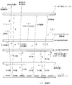
この際、図11に示すパターンに光描画を行い、領域Aにおいて生じる透過光の位相差(複屈折効果)と、領域Bにおいて生じる透過光の位相差(複屈折効果)と、領域Cにおいて生じる透過光の位相差(複屈折効果)とが異なるものとなるように調整する。すなわち、各領域において、光学異方性が異なる状態となるようにする。なお、領域Dは、光照射を行わず、複屈折効果が生じない単なる光透過層とする。
上記の位相差の調整は、照射する光の光量(露光量)を変えることで行う。その後、200℃の温度で熱処理を加えることで、光の照射光量に応じた配向状態の固定化の状態が決まり、それにより部分的に複屈折の状態が異なる光学異方性層301が得られる。なお、光を当てないと、熱処理時に配向状態が乱れ、その領域の複屈折性は消失する(単なる光透過層となる)。上記の熱処理は、50℃~400℃の範囲から選択された温度で行うことができる。
こうして、平面内における直交方向の屈折率に差があり、しかもその差の状態が図11に示す領域A、領域B、領域Cにおいて異なっている光学異方性層301が得られる。この例では、円偏光フィルタを用いた観察時において、領域A、領域B、領域Cが異なる色彩に見えるように、それら領域で生じる位相差の設定がされている。なお、領域Dは、屈性率異方性がない、単なる光透過領域として形成される。
光学異方性層301を得たら、それを図示しない易剥離層から剥離し、保護層101に固定する。この後、可視光全域反射コレステリック液晶層105との積層、更に粘着層107の形成およびセパレータ108の貼り付けを行い図10に示す識別媒体400を得る。
識別媒体400の対象物への固定は、セパレータ108を剥がし、粘着層107を対象物に接触させることで行われる。この点は、図1の識別媒体100と同じである。なお、可視光全域反射コレステリック液晶層105が選択反射する円偏光の旋回方向は、右旋回に限定されず、左旋回であってもよい。
(光学機能)
図10の識別媒体400を図の上の方向から直視した場合、領域A~Cの複屈折効果は視認できず、また領域Dは単なる光透過層であるので、図11に示すABCの表示は観察されない。右円偏光フィルタを介して識別媒体400を観察すると、領域ABCを透過してきた光は、複屈折効果により楕円偏光化し、またその楕円偏光の状態は、領域ABCのそれぞれにおいて異なるので、領域ABCのそれぞれが異なった色彩に見える。領域Dは、可視光全域反射コレステリック液晶層105から反射された可視光全域の光が観察され、例えば金属光沢を持った反射光が観察される。
図10の識別媒体400を図の上の方向から直視した場合、領域A~Cの複屈折効果は視認できず、また領域Dは単なる光透過層であるので、図11に示すABCの表示は観察されない。右円偏光フィルタを介して識別媒体400を観察すると、領域ABCを透過してきた光は、複屈折効果により楕円偏光化し、またその楕円偏光の状態は、領域ABCのそれぞれにおいて異なるので、領域ABCのそれぞれが異なった色彩に見える。領域Dは、可視光全域反射コレステリック液晶層105から反射された可視光全域の光が観察され、例えば金属光沢を持った反射光が観察される。
領域A、B、Cの部分からの反射光が異なる色彩に見えるのは、以下の理由による。すなわち、領域ABCのそれぞれにおいて、光学異方性層301内で直交する偏光の成分に位相差が生じるのであるが、この生じる位相差に波長依存性があるので、ある偏光成分に着目すると、光学異方性層301内で生じた位相差に応じた波長を中心にした色が見える。このため、生じた位相差の違いによって異なる色彩が観察される。ここで、領域A、B、Cの部分では、生じる位相差が異なる状態となるように設定されているので、円偏光フィルタを介した観察において、領域A、B、Cの部分が異なる色彩に見える。
また、左円偏光フィルタを介して識別媒体400を見ると、領域A、B、Cの部分が右円偏光フィルタを用いた場合と異なる色彩で見える。これは、円偏光フィルタで抽出された偏光成分が、右円偏光フィルタを用いた場合と異なるからである。またこの際も、領域A、B、Cのそれぞれは異なる色に見える。また、領域Dからの右円偏光の反射光は、左円偏光フィルタで遮断されるので、可視光全域反射コレステリック液晶層105からの反射光は見えず、可視光全域反射コレステリック液晶層105の下地である粘着層107が見える。ここで、粘着層107が着色されていれば、その色が領域Dの部分で見え、粘着層107が透明であれば、粘着層107の更に下層の表面が領域Dの部分で見える。
以上述べたように、図10には、観察される側から、光学異方性の状態が異なる複数の領域を備えた光学異方性層と、可視光全域反射コレステリック液晶層とが配置された構造を有している。
(4)その他の開示内容2
図12には、識別媒体500が示されている。識別媒体500は、観察する側から保護層101、ホログラム加工103が施されたコレステリック液晶層102、λ/2板401、可視光全域反射コレステリック液晶層105、粘着層107、セパレータ108と積層された構造を有している。ここで、コレステリック液晶層102は赤の右円偏光を選択反射する設定であり、可視光全域反射コレステリック液晶層105は、右円偏光の可視光全域反射を行う設定とされている。
図12には、識別媒体500が示されている。識別媒体500は、観察する側から保護層101、ホログラム加工103が施されたコレステリック液晶層102、λ/2板401、可視光全域反射コレステリック液晶層105、粘着層107、セパレータ108と積層された構造を有している。ここで、コレステリック液晶層102は赤の右円偏光を選択反射する設定であり、可視光全域反射コレステリック液晶層105は、右円偏光の可視光全域反射を行う設定とされている。
右円偏光フィルタを介して識別媒体500を図の上の方向から観察すると、コレステリック液晶層102から反射された例えば赤の右円偏光が観察される。このため、ホログラム加工103に起因するホログラムが観察される。左円偏光フィルタを介して識別媒体500を観察すると、コレステリック液晶層102からの反射光は観察できない。他方において、可視光全域反射コレステリック液晶層105から反射された右円偏光がλ/2板401で反転し、左円偏光となるので、コレステリック液晶層102を上方へそのまま透過するので、可視光全域反射コレステリック液晶層105からの反射光が観察可能となる。この反射光は、左円偏光であり、可視光全域の光として観察されるので、コレステリック液晶102のホログラムが見えない状態で、例えば金属光沢を持った反射光が観察される。
なお、可視光全域反射コレステリック液晶層105から反射される円偏光の旋回方向を左旋回とした場合、λ/2板401は省略できる。また、コレステリック液晶層102の選択反射波長を赤以外の他の色とすることも可能であり、また選択反射される円偏光の旋回方向を左旋回とする設定も可能である。
以上述べたように、図12には、観察される側から、ホログラム加工が施されたコレステリック液晶層と、λ/2板と、前記コレステリック液晶層と同じ旋回方向の円偏光を選択反射する可視光全域反射コレステリック液晶層とを備えている。なお、λ/2板を省略したい場合は、可視光全域反射コレステリック液晶層から反射される円偏光の旋回方向をコレステリック液晶層と逆とする。
本発明は、真贋の識別を行うための技術に利用することができる。
Claims (4)
- 観察が行われる側から、
ホログラム加工が施され、特定中心波長の特定旋回方向の円偏光を選択的に反射する第1のコレステリック液晶層と、
可視光全域の光を反射する反射特性または可視光全域の光を反射する場合と等価な反射特性を有し、前記第1のコレステリック液晶層から反射される円偏光と同じ旋回方向の円偏光を反射する第2のコレステリック液晶層と、
特定の表示内容とされた表示パターンと
配置された構造を有することを特徴とする識別媒体。 - 前記第2のコレステリック液晶層と前記表示パターンとの間に屈折率異方性を有する光透過層が設けられていることを特徴とする請求項1に記載の識別媒体。
- 観察が行われる側から、
ホログラム加工が施され、特定中心波長の特定旋回方向の円偏光を選択的に反射する第1のコレステリック液晶層と、
可視光全域の光を反射する反射特性または可視光全域の光を反射する場合と等価な反射特性を有し、前記第1のコレステリック液晶層から反射される円偏光と同じ旋回方向の円偏光を反射する第2のコレステリック液晶層と、
光透過性を有する粘着層と
を備えることを特徴とする識別媒体。 - 前記第1のコレステリック液晶層が一方の面に接触し、前記第2のコレステリック液晶層が他方の面に接触したシクロオレフィンポリマーの層を備えることを特徴とする請求項1~3のいずれか一項に記載の識別媒体。
Priority Applications (3)
| Application Number | Priority Date | Filing Date | Title |
|---|---|---|---|
| US14/006,038 US9298036B2 (en) | 2011-03-18 | 2012-03-08 | Identification medium |
| CN201280014299.5A CN103562757B (zh) | 2011-03-18 | 2012-03-08 | 识别介质 |
| EP12760512.9A EP2687879B1 (en) | 2011-03-18 | 2012-03-08 | Distinguishing medium |
Applications Claiming Priority (2)
| Application Number | Priority Date | Filing Date | Title |
|---|---|---|---|
| JP2011061184A JP5647047B2 (ja) | 2011-03-18 | 2011-03-18 | 識別媒体 |
| JP2011-061184 | 2011-03-18 |
Publications (1)
| Publication Number | Publication Date |
|---|---|
| WO2012128057A1 true WO2012128057A1 (ja) | 2012-09-27 |
Family
ID=46879211
Family Applications (1)
| Application Number | Title | Priority Date | Filing Date |
|---|---|---|---|
| PCT/JP2012/055977 Ceased WO2012128057A1 (ja) | 2011-03-18 | 2012-03-08 | 識別媒体 |
Country Status (5)
| Country | Link |
|---|---|
| US (1) | US9298036B2 (ja) |
| EP (1) | EP2687879B1 (ja) |
| JP (1) | JP5647047B2 (ja) |
| CN (1) | CN103562757B (ja) |
| WO (1) | WO2012128057A1 (ja) |
Cited By (2)
| Publication number | Priority date | Publication date | Assignee | Title |
|---|---|---|---|---|
| CN105190654A (zh) * | 2013-03-21 | 2015-12-23 | 日本发条株式会社 | 识别介质、码信息的读取方法、码信息的读取装置、识别介质的制造方法以及识别介质的制造装置 |
| WO2022168690A1 (ja) * | 2021-02-05 | 2022-08-11 | 日本ゼオン株式会社 | 光学積層体及びその真正性の判定方法、並びに物品 |
Families Citing this family (16)
| Publication number | Priority date | Publication date | Assignee | Title |
|---|---|---|---|---|
| WO2012137550A1 (ja) * | 2011-04-01 | 2012-10-11 | 日本発條株式会社 | 識別媒体 |
| US9243169B2 (en) * | 2013-05-16 | 2016-01-26 | Sicpa Holding Sa | Security laminate |
| WO2015025909A1 (ja) * | 2013-08-21 | 2015-02-26 | 富士フイルム株式会社 | 円偏光フィルターおよびその応用 |
| WO2016088708A1 (ja) * | 2014-12-01 | 2016-06-09 | 富士フイルム株式会社 | 画像表示機能付きミラー |
| JP6314249B2 (ja) * | 2014-12-01 | 2018-04-18 | 富士フイルム株式会社 | 画像表示機能付きミラー |
| JP6458658B2 (ja) * | 2015-06-15 | 2019-01-30 | 凸版印刷株式会社 | 透かし用紙 |
| DE102016003967A1 (de) * | 2016-04-01 | 2017-10-05 | Giesecke+Devrient Currency Technology Gmbh | Datenträger mit Aufdruck |
| DE102017116736B3 (de) * | 2017-07-25 | 2018-12-13 | Infineon Technologies Ag | Chipkartenmodul, verfahren zum herstellen eines chipkartenmoduls, chipkarte und verfahren zum prüfen eines chipkartenmoduls |
| EP3805824B1 (en) * | 2018-05-31 | 2024-10-09 | Zeon Corporation | Identification medium, and method for determining authenticity of identification medium |
| JP7396275B2 (ja) * | 2018-06-29 | 2023-12-12 | 日本ゼオン株式会社 | 識別媒体、真正性判定方法、及び物品 |
| US11988856B2 (en) * | 2019-06-26 | 2024-05-21 | Zeon Corporation | Display medium, authenticity determination method, and article including display medium |
| WO2021020024A1 (ja) | 2019-07-31 | 2021-02-04 | 日本ゼオン株式会社 | 表示媒体、表示物品及び表示セット |
| WO2021065484A1 (ja) * | 2019-09-30 | 2021-04-08 | 日本ゼオン株式会社 | 表示媒体、表示物品及び表示セット |
| KR102441227B1 (ko) * | 2020-05-13 | 2022-09-07 | 엔비에스티(주) | 콜레스테릭 액정 표시층을 포함하는 연포장재 |
| JP7552479B2 (ja) * | 2021-03-30 | 2024-09-18 | 日本ゼオン株式会社 | 識別媒体、製造方法、物品、及び識別媒体の使用方法 |
| CN114779520A (zh) * | 2022-05-25 | 2022-07-22 | 深圳蓝鲸世纪科技有限公司 | 光学系统和显示设备 |
Citations (7)
| Publication number | Priority date | Publication date | Assignee | Title |
|---|---|---|---|---|
| JP3373374B2 (ja) | 1995-11-09 | 2003-02-04 | 日東電工株式会社 | 偏光素子及び楕円偏光素子 |
| JP2004338257A (ja) * | 2003-05-16 | 2004-12-02 | Nhk Spring Co Ltd | 対象物の識別媒体及び識別方法 |
| JP2005134490A (ja) * | 2003-10-28 | 2005-05-26 | Nhk Spring Co Ltd | 識別媒体、識別媒体の識別方法、識別対象物品および識別装置 |
| JP2007069486A (ja) * | 2005-09-07 | 2007-03-22 | Dainippon Printing Co Ltd | 体積型ホログラム付きコレステリック液晶媒体の製造方法 |
| JP2009172798A (ja) | 2008-01-22 | 2009-08-06 | Nhk Spring Co Ltd | 識別媒体およびその製造方法 |
| JP2009175208A (ja) | 2008-01-22 | 2009-08-06 | Fujifilm Corp | 複屈折パターンを有する物品の製造方法 |
| JP2009216722A (ja) * | 2008-03-06 | 2009-09-24 | Toppan Printing Co Ltd | セキュリティデバイス及びラベル付き物品 |
Family Cites Families (7)
| Publication number | Priority date | Publication date | Assignee | Title |
|---|---|---|---|---|
| JP4335352B2 (ja) | 1999-03-05 | 2009-09-30 | 大日本印刷株式会社 | 偽造防止体及び偽造判別方法 |
| DE102004021246A1 (de) | 2004-04-30 | 2005-11-24 | Giesecke & Devrient Gmbh | Sicherheitselement und Verfahren zu seiner Herstellung |
| US20080138543A1 (en) | 2004-12-24 | 2008-06-12 | Nhk Spring Co., Ltd. | Identification Medium, Article Equipped With Identification Medium, Identifying Method And Device |
| JP4866129B2 (ja) * | 2006-04-03 | 2012-02-01 | 日本発條株式会社 | 識別媒体、識別方法および識別装置 |
| JP4959304B2 (ja) * | 2006-11-22 | 2012-06-20 | 日本発條株式会社 | 識別媒体、識別方法および識別装置 |
| JP5231163B2 (ja) * | 2008-10-14 | 2013-07-10 | 日本発條株式会社 | 識別媒体および物品 |
| KR101798584B1 (ko) * | 2010-06-24 | 2017-11-17 | 삼성전자주식회사 | 광학 보상 필름 및 그 제조 방법과 상기 광학 보상 필름을 구비하는 액정 표시 장치 |
-
2011
- 2011-03-18 JP JP2011061184A patent/JP5647047B2/ja active Active
-
2012
- 2012-03-08 EP EP12760512.9A patent/EP2687879B1/en active Active
- 2012-03-08 WO PCT/JP2012/055977 patent/WO2012128057A1/ja not_active Ceased
- 2012-03-08 US US14/006,038 patent/US9298036B2/en active Active
- 2012-03-08 CN CN201280014299.5A patent/CN103562757B/zh active Active
Patent Citations (8)
| Publication number | Priority date | Publication date | Assignee | Title |
|---|---|---|---|---|
| JP3373374B2 (ja) | 1995-11-09 | 2003-02-04 | 日東電工株式会社 | 偏光素子及び楕円偏光素子 |
| JP2004338257A (ja) * | 2003-05-16 | 2004-12-02 | Nhk Spring Co Ltd | 対象物の識別媒体及び識別方法 |
| JP4392826B2 (ja) | 2003-05-16 | 2010-01-06 | 日本発條株式会社 | 対象物の識別媒体及び識別方法 |
| JP2005134490A (ja) * | 2003-10-28 | 2005-05-26 | Nhk Spring Co Ltd | 識別媒体、識別媒体の識別方法、識別対象物品および識別装置 |
| JP2007069486A (ja) * | 2005-09-07 | 2007-03-22 | Dainippon Printing Co Ltd | 体積型ホログラム付きコレステリック液晶媒体の製造方法 |
| JP2009172798A (ja) | 2008-01-22 | 2009-08-06 | Nhk Spring Co Ltd | 識別媒体およびその製造方法 |
| JP2009175208A (ja) | 2008-01-22 | 2009-08-06 | Fujifilm Corp | 複屈折パターンを有する物品の製造方法 |
| JP2009216722A (ja) * | 2008-03-06 | 2009-09-24 | Toppan Printing Co Ltd | セキュリティデバイス及びラベル付き物品 |
Cited By (6)
| Publication number | Priority date | Publication date | Assignee | Title |
|---|---|---|---|---|
| CN105190654A (zh) * | 2013-03-21 | 2015-12-23 | 日本发条株式会社 | 识别介质、码信息的读取方法、码信息的读取装置、识别介质的制造方法以及识别介质的制造装置 |
| EP2977935A4 (en) * | 2013-03-21 | 2016-11-23 | Nhk Spring Co Ltd | IDENTIFICATION MEDIA, CODE INFORMATION READING, CODE INFORMATION READER, IDENTIFICATION MEDIUM MANUFACTURING METHOD AND IDENTIFICATION MEDIUM MANAGEMENT DEVICE |
| CN105190654B (zh) * | 2013-03-21 | 2019-11-05 | 日本发条株式会社 | 识别介质、码信息的读取方法、码信息的读取装置、识别介质的制造方法以及识别介质的制造装置 |
| WO2022168690A1 (ja) * | 2021-02-05 | 2022-08-11 | 日本ゼオン株式会社 | 光学積層体及びその真正性の判定方法、並びに物品 |
| JPWO2022168690A1 (ja) * | 2021-02-05 | 2022-08-11 | ||
| CN116829994A (zh) * | 2021-02-05 | 2023-09-29 | 日本瑞翁株式会社 | 光学层叠体及其真实性的判断方法、以及物品 |
Also Published As
| Publication number | Publication date |
|---|---|
| EP2687879B1 (en) | 2017-08-30 |
| CN103562757A (zh) | 2014-02-05 |
| JP5647047B2 (ja) | 2014-12-24 |
| EP2687879A1 (en) | 2014-01-22 |
| US9298036B2 (en) | 2016-03-29 |
| JP2012198316A (ja) | 2012-10-18 |
| EP2687879A4 (en) | 2014-10-01 |
| US20140022493A1 (en) | 2014-01-23 |
| CN103562757B (zh) | 2016-11-09 |
Similar Documents
| Publication | Publication Date | Title |
|---|---|---|
| JP5647047B2 (ja) | 識別媒体 | |
| JP4875003B2 (ja) | 識別媒体およびその製造方法 | |
| KR101392614B1 (ko) | 식별 매체 및 그 식별 방법 | |
| KR101531439B1 (ko) | 식별 매체 및 그 식별 방법 | |
| CN101501537B (zh) | 识别介质、识别介质的制造方法、物品和识别介质的识别方法 | |
| JP2005134490A (ja) | 識別媒体、識別媒体の識別方法、識別対象物品および識別装置 | |
| WO2004102234A1 (ja) | 対象物の識別媒体及び識別方法 | |
| WO2006068180A1 (ja) | 識別媒体、識別媒体を備えた物品、識別方法および識別装置 | |
| JP2015089638A (ja) | 偽造防止用デバイスおよびその製造方法 | |
| JP6179086B2 (ja) | 偽造防止媒体、それを用いた偽造防止ステッカーおよび偽造防止物品 | |
| JP4978403B2 (ja) | 光学素子、ラベル付き物品、光学キット及び判別方法 | |
| JP2005022292A (ja) | 対象物の識別構造およびその構造が設けられた対象物 | |
| JP2011126199A (ja) | 画像表示体、ブランク媒体及び個人認証媒体 | |
| JP6927886B2 (ja) | 光学セキュリティ装置 | |
| WO2017204168A1 (ja) | 偽造防止媒体 | |
| JP5811568B2 (ja) | 偽造防止媒体 | |
| JP5245473B2 (ja) | セキュリティデバイス及びラベル付き物品 | |
| CN113665206B (zh) | 包括胆甾相液晶显示层的软包装材料 | |
| JP2013064882A (ja) | 情報記録媒体 | |
| JP2008139509A (ja) | 積層体、粘着ラベル、記録媒体、ラベル付き物品及び判別方法 | |
| JP2014021152A (ja) | 識別媒体および識別方法 |
Legal Events
| Date | Code | Title | Description |
|---|---|---|---|
| 121 | Ep: the epo has been informed by wipo that ep was designated in this application |
Ref document number: 12760512 Country of ref document: EP Kind code of ref document: A1 |
|
| NENP | Non-entry into the national phase |
Ref country code: DE |
|
| WWE | Wipo information: entry into national phase |
Ref document number: 14006038 Country of ref document: US |
|
| REEP | Request for entry into the european phase |
Ref document number: 2012760512 Country of ref document: EP |
|
| WWE | Wipo information: entry into national phase |
Ref document number: 2012760512 Country of ref document: EP |