WO2012128057A1 - Support distinctif - Google Patents
Support distinctif Download PDFInfo
- Publication number
- WO2012128057A1 WO2012128057A1 PCT/JP2012/055977 JP2012055977W WO2012128057A1 WO 2012128057 A1 WO2012128057 A1 WO 2012128057A1 JP 2012055977 W JP2012055977 W JP 2012055977W WO 2012128057 A1 WO2012128057 A1 WO 2012128057A1
- Authority
- WO
- WIPO (PCT)
- Prior art keywords
- liquid crystal
- cholesteric liquid
- crystal layer
- light
- circularly polarized
- Prior art date
- Legal status (The legal status is an assumption and is not a legal conclusion. Google has not performed a legal analysis and makes no representation as to the accuracy of the status listed.)
- Ceased
Links
Images


Classifications
-
- B—PERFORMING OPERATIONS; TRANSPORTING
- B42—BOOKBINDING; ALBUMS; FILES; SPECIAL PRINTED MATTER
- B42D—BOOKS; BOOK COVERS; LOOSE LEAVES; PRINTED MATTER CHARACTERISED BY IDENTIFICATION OR SECURITY FEATURES; PRINTED MATTER OF SPECIAL FORMAT OR STYLE NOT OTHERWISE PROVIDED FOR; DEVICES FOR USE THEREWITH AND NOT OTHERWISE PROVIDED FOR; MOVABLE-STRIP WRITING OR READING APPARATUS
- B42D25/00—Information-bearing cards or sheet-like structures characterised by identification or security features; Manufacture thereof
- B42D25/40—Manufacture
- B42D25/45—Associating two or more layers
- B42D25/465—Associating two or more layers using chemicals or adhesives
- B42D25/47—Associating two or more layers using chemicals or adhesives using adhesives
-
- B—PERFORMING OPERATIONS; TRANSPORTING
- B42—BOOKBINDING; ALBUMS; FILES; SPECIAL PRINTED MATTER
- B42D—BOOKS; BOOK COVERS; LOOSE LEAVES; PRINTED MATTER CHARACTERISED BY IDENTIFICATION OR SECURITY FEATURES; PRINTED MATTER OF SPECIAL FORMAT OR STYLE NOT OTHERWISE PROVIDED FOR; DEVICES FOR USE THEREWITH AND NOT OTHERWISE PROVIDED FOR; MOVABLE-STRIP WRITING OR READING APPARATUS
- B42D25/00—Information-bearing cards or sheet-like structures characterised by identification or security features; Manufacture thereof
- B42D25/30—Identification or security features, e.g. for preventing forgery
- B42D25/328—Diffraction gratings; Holograms
-
- B—PERFORMING OPERATIONS; TRANSPORTING
- B42—BOOKBINDING; ALBUMS; FILES; SPECIAL PRINTED MATTER
- B42D—BOOKS; BOOK COVERS; LOOSE LEAVES; PRINTED MATTER CHARACTERISED BY IDENTIFICATION OR SECURITY FEATURES; PRINTED MATTER OF SPECIAL FORMAT OR STYLE NOT OTHERWISE PROVIDED FOR; DEVICES FOR USE THEREWITH AND NOT OTHERWISE PROVIDED FOR; MOVABLE-STRIP WRITING OR READING APPARATUS
- B42D25/00—Information-bearing cards or sheet-like structures characterised by identification or security features; Manufacture thereof
- B42D25/30—Identification or security features, e.g. for preventing forgery
- B42D25/36—Identification or security features, e.g. for preventing forgery comprising special materials
- B42D25/364—Liquid crystals
-
- B—PERFORMING OPERATIONS; TRANSPORTING
- B42—BOOKBINDING; ALBUMS; FILES; SPECIAL PRINTED MATTER
- B42D—BOOKS; BOOK COVERS; LOOSE LEAVES; PRINTED MATTER CHARACTERISED BY IDENTIFICATION OR SECURITY FEATURES; PRINTED MATTER OF SPECIAL FORMAT OR STYLE NOT OTHERWISE PROVIDED FOR; DEVICES FOR USE THEREWITH AND NOT OTHERWISE PROVIDED FOR; MOVABLE-STRIP WRITING OR READING APPARATUS
- B42D25/00—Information-bearing cards or sheet-like structures characterised by identification or security features; Manufacture thereof
- B42D25/30—Identification or security features, e.g. for preventing forgery
- B42D25/36—Identification or security features, e.g. for preventing forgery comprising special materials
- B42D25/378—Special inks
- B42D25/391—Special inks absorbing or reflecting polarised light
-
- G—PHYSICS
- G02—OPTICS
- G02F—OPTICAL DEVICES OR ARRANGEMENTS FOR THE CONTROL OF LIGHT BY MODIFICATION OF THE OPTICAL PROPERTIES OF THE MEDIA OF THE ELEMENTS INVOLVED THEREIN; NON-LINEAR OPTICS; FREQUENCY-CHANGING OF LIGHT; OPTICAL LOGIC ELEMENTS; OPTICAL ANALOGUE/DIGITAL CONVERTERS
- G02F1/00—Devices or arrangements for the control of the intensity, colour, phase, polarisation or direction of light arriving from an independent light source, e.g. switching, gating or modulating; Non-linear optics
- G02F1/01—Devices or arrangements for the control of the intensity, colour, phase, polarisation or direction of light arriving from an independent light source, e.g. switching, gating or modulating; Non-linear optics for the control of the intensity, phase, polarisation or colour
- G02F1/13—Devices or arrangements for the control of the intensity, colour, phase, polarisation or direction of light arriving from an independent light source, e.g. switching, gating or modulating; Non-linear optics for the control of the intensity, phase, polarisation or colour based on liquid crystals, e.g. single liquid crystal display cells
- G02F1/133—Constructional arrangements; Operation of liquid crystal cells; Circuit arrangements
- G02F1/1333—Constructional arrangements; Manufacturing methods
- G02F1/1334—Constructional arrangements; Manufacturing methods based on polymer dispersed liquid crystals, e.g. microencapsulated liquid crystals
- G02F1/13342—Holographic polymer dispersed liquid crystals
-
- G—PHYSICS
- G02—OPTICS
- G02F—OPTICAL DEVICES OR ARRANGEMENTS FOR THE CONTROL OF LIGHT BY MODIFICATION OF THE OPTICAL PROPERTIES OF THE MEDIA OF THE ELEMENTS INVOLVED THEREIN; NON-LINEAR OPTICS; FREQUENCY-CHANGING OF LIGHT; OPTICAL LOGIC ELEMENTS; OPTICAL ANALOGUE/DIGITAL CONVERTERS
- G02F1/00—Devices or arrangements for the control of the intensity, colour, phase, polarisation or direction of light arriving from an independent light source, e.g. switching, gating or modulating; Non-linear optics
- G02F1/01—Devices or arrangements for the control of the intensity, colour, phase, polarisation or direction of light arriving from an independent light source, e.g. switching, gating or modulating; Non-linear optics for the control of the intensity, phase, polarisation or colour
- G02F1/13—Devices or arrangements for the control of the intensity, colour, phase, polarisation or direction of light arriving from an independent light source, e.g. switching, gating or modulating; Non-linear optics for the control of the intensity, phase, polarisation or colour based on liquid crystals, e.g. single liquid crystal display cells
- G02F1/133—Constructional arrangements; Operation of liquid crystal cells; Circuit arrangements
- G02F1/1333—Constructional arrangements; Manufacturing methods
- G02F1/1335—Structural association of cells with optical devices, e.g. polarisers or reflectors
- G02F1/133553—Reflecting elements
-
- G—PHYSICS
- G09—EDUCATION; CRYPTOGRAPHY; DISPLAY; ADVERTISING; SEALS
- G09F—DISPLAYING; ADVERTISING; SIGNS; LABELS OR NAME-PLATES; SEALS
- G09F3/00—Labels, tag tickets, or similar identification or indication means; Seals; Postage or like stamps
- G09F3/02—Forms or constructions
- G09F3/0291—Labels or tickets undergoing a change under particular conditions, e.g. heat, radiation, passage of time
- G09F3/0294—Labels or tickets undergoing a change under particular conditions, e.g. heat, radiation, passage of time where the change is not permanent, e.g. labels only readable under a special light, temperature indicating labels and the like
-
- G—PHYSICS
- G09—EDUCATION; CRYPTOGRAPHY; DISPLAY; ADVERTISING; SEALS
- G09F—DISPLAYING; ADVERTISING; SIGNS; LABELS OR NAME-PLATES; SEALS
- G09F3/00—Labels, tag tickets, or similar identification or indication means; Seals; Postage or like stamps
- G09F3/02—Forms or constructions
- G09F3/03—Forms or constructions of security seals
- G09F3/0305—Forms or constructions of security seals characterised by the type of seal used
- G09F3/0341—Forms or constructions of security seals characterised by the type of seal used having label sealing means
Definitions
- the present invention relates to an identification medium capable of observing clear switching of observation contents.
- Patent Document 1 a first cholesteric liquid crystal layer that is subjected to hologram processing and selectively reflects right circularly polarized light, and a second cholesteric liquid crystal layer that is subjected to hologram processing and selectively reflects left circularly polarized light are stacked.
- the structure describes a structure in which switching between two hologram patterns can be observed in selective observation using the left and right circular polarization filters.
- Patent Document 2 describes a configuration in which a hologram pattern and a printed pattern can be observed when a cholesteric liquid crystal layer subjected to hologram processing and a printed layer are combined and observed through a circular polarizing filter.
- an object of the present invention is to provide an identification medium capable of observing clear image switching with a structure obtained at low cost.
- a first cholesteric liquid crystal layer that is subjected to hologram processing and selectively reflects circularly polarized light having a specific center wavelength in a specific turning direction, and light in the entire visible light region.
- a second cholesteric that has a reflection characteristic to reflect or a reflection characteristic equivalent to the case of reflecting light in the entire visible light region and reflects circularly polarized light in the same turning direction as the circularly polarized light reflected from the first cholesteric liquid crystal layer
- An identification medium having a structure in which a liquid crystal layer, a display pattern having specific display contents, and a display pattern are arranged.
- the property of the second cholesteric liquid crystal layer that selectively transmits circularly polarized light that has a specific rotation and has a wavelength distribution over the entire visible light range is obtained.
- the display content of the display pattern is clearly observed without being obstructed by the hologram of the first cholesteric liquid crystal layer in the observation through the circular polarization filter that blocks selectively reflected light from the first cholesteric liquid crystal layer. can do.
- light that is reflected from the display pattern and cannot pass through the second cholesteric liquid crystal layer and is reflected again in the direction of the display pattern on the lower surface thereof can be transmitted through the second cholesteric liquid crystal layer by repeating reflection.
- Polarized light is emitted from the identification medium as light for recognizing the display pattern. For this reason, the visibility at the time of selectively visually recognizing the display pattern through the circularly polarizing filter is enhanced.
- a light transmission layer having refractive index anisotropy is provided between the second cholesteric liquid crystal layer and the display pattern.
- a first cholesteric liquid crystal layer that is subjected to hologram processing and selectively reflects circularly polarized light having a specific center wavelength in a specific turning direction from the observation side;
- a second reflection member that has a reflection characteristic that reflects light or a reflection characteristic that is equivalent to the case of reflecting light in the entire visible light region, and that reflects circularly polarized light in the same turning direction as the circularly polarized light reflected from the first cholesteric liquid crystal layer.
- the cholesteric liquid crystal layer and a light-transmitting adhesive layer are provided.
- the adhesive layer is light-transmitting (property of transmitting visible light)
- the display using the display on the surface of the object in a state of being attached to the object.
- An optical function similar to that of the invention of Item 1 can be obtained.
- the invention of claim 4 is the invention according to any one of claims 1 to 3, wherein the first cholesteric liquid crystal layer is in contact with the one surface, the second cholesteric liquid crystal layer and the other It comprises a layer of cycloolefin polymer in contact with the surface.
- Cycloolefin polymers are inexpensive and have chemical properties that are very susceptible to degradation when in contact with hydrocarbon solvents such as gasoline, kerosene, thinner, benzine, and so on, and may be peeled off in contact with the solvent. It has a physical property that tends to cause breakage and wrinkles when a large force is applied. For this reason, by adopting the invention according to claim 3, the layer structure of the identification medium is destroyed and re-established when the identification medium is illegally removed or forcibly removed from the object. It can be a structure that cannot be used. This property is useful for preventing or making unauthorized reuse of the identification medium 100 difficult.
- hydrocarbon solvents such as gasoline, kerosene, thinner, benzine, and so on
- the cycloolefin polymer has the above-described advantages, but has a physical property that streaks or cracks are caused by physical contact from the outside (for example, by touching with a hand). Yes. When this phenomenon occurs, there arises a problem that it is visually recognized. According to the invention described in claim 4, since the cycloolefin polymer layer is sandwiched from the front and back by the cholesteric liquid crystal layer and the visible light total reflection cholesteric liquid crystal layer, Contact from the outside to the layer is prevented, and the above-described problem of generation of streaks and cracks does not occur.
- an identification medium can be obtained in which clear image switching can be observed with a structure obtained at low cost.
- DESCRIPTION OF SYMBOLS 100 ... Identification medium, 101 ... Protective layer, 102 ... Cholesteric liquid crystal layer, 103 ... Hologram processing, 104 ... COP (cycloolefin polymer) layer, 105 ... Visible light whole reflection cholesteric liquid crystal layer, 105a ... Cholesteric liquid crystal layer, 105b ... Cholesteric Liquid crystal layer, 105c ... cholesteric liquid crystal layer, 106 ... display pattern, 107 ... adhesive layer, 108 ... separator, 109 ... object, 110 ... birefringent layer, 200 ... identification medium, 300 ... identification medium, 301 ... optical anisotropy Layer, 400 ... identification medium, 500 ... identification medium.
- COP cycloolefin polymer
- FIG. 1A shows an identification medium 100 of the embodiment.
- the identification medium 100 has a structure in which a protective layer 101, a cholesteric liquid crystal layer 102, a visible light all-reflection cholesteric liquid crystal layer 105, a display pattern 106, an adhesive layer 107, and a separator 108 are stacked from the observation side.
- the protective layer 101 protects the observation surface and is a thin film made of a material that has a light-transmitting property with respect to visible light and does not disturb the polarization state of the transmitted light. Examples of the material constituting the protective layer 101 include triacetyl cellulose, acrylic, and cycloolefin.
- the protective layer 101 since cycloolefin has poor oil resistance, when the cycloolefin is used as the protective layer 101, the protective layer is used when the identification medium 100 is peeled off by dropping a solvent or oil after being attached to an object. An advantage is obtained in that 101 collapses and the identification medium 100 cannot be reused after being illegally peeled off.
- the cholesteric liquid crystal layer 102 is configured to selectively reflect red right-handed circularly polarized light, and is formed by pressing an emboss type against the surface opposite to the observation surface (the lower surface in FIG. 1). Hologram processing 103 is performed. When the reflected light from the cholesteric liquid crystal layer 102 is observed, a hologram image based on the hologram processing 103 is observed.
- the turning direction of the circularly polarized light selectively reflected by the cholesteric liquid crystal layer 102 may be a left turn. However, the turning direction is set to be the same as the turning direction of circularly polarized light selectively reflected by the visible light all-reflection cholesteric liquid crystal layer 105 described later. Further, the center wavelength of the circularly polarized light selectively reflected by the cholesteric liquid crystal layer 102 can be selected from other materials such as green according to the purpose of use and the visual recognition function.
- the left circularly polarized light is set to be selectively reflected from the cholesteric liquid crystal layer 102
- the left circularly polarized light is also set to be selectively reflected from the visible light entire reflection cholesteric liquid crystal layer 105. That is, the turning direction of the circularly polarized light reflected by the visible light all-reflection cholesteric liquid crystal layer 105 is set to be the same as the turning direction of the circularly polarized light selectively reflected by the cholesteric liquid crystal layer 102.
- the visible light all-reflection cholesteric liquid crystal layer 105 selectively reflects circularly polarized light in the entire visible light band (or a wavelength spectrum that can be regarded as such) in a specific turning direction.
- linearly polarized light and circularly polarized light in the reverse turning direction are transmitted.
- This optical characteristic can be obtained by combining a plurality of cholesteric liquid crystal layers having a pitch.
- the visible light full range cholesteric liquid crystal is described in, for example, Japanese Patent No. 3373374.
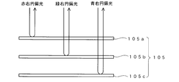
- FIG. 2 conceptually shows a cross-sectional structure of the visible light total reflection cholesteric liquid crystal layer 105.
- the visible light all-reflection cholesteric liquid crystal layer 105 includes three layers, a first cholesteric liquid crystal layer 105a, a second cholesteric liquid crystal layer 105b, and a third cholesteric liquid crystal layer 105c.
- these three layers are illustrated as if they are separated from each other, but actually, they are stacked and integrated.
- the cholesteric liquid crystal layer 105a is set to selectively reflect red (wavelength 650 ⁇ 50 nm) right-handed circularly polarized light
- the cholesteric liquid crystal layer 105b selectively selects green (wavelength 550 ⁇ 50 nm) right-handed circularly polarized light
- the cholesteric liquid crystal layer 105c is set to selectively reflect blue (wavelength 450 ⁇ 50 nm) right circularly polarized light.
- the first cholesteric liquid crystal layer 105a transmits the green and blue wavelength components regardless of the polarization state
- the second cholesteric liquid crystal 105b transmits the blue wavelength component regardless of the polarization state. Therefore, as shown in FIG. 2, red, green, and blue right-handed circularly polarized light is reflected in the upward direction of FIG. 2 from the visible light whole reflection cholesteric liquid crystal layer 105.
- the human eye sees a state equivalent to the case where the entire light in the visible light band is visually recognized. That is, optical characteristics equivalent to the case of circularly polarized light having a specific rotation (right circularly polarized light in the case of FIG.
- cholesteric liquid crystal layer 105 that reflects the entire visible light region
- three types of cholesteric liquid crystal having a characteristic of selectively reflecting red, green, and blue circularly polarized light in the same rotation direction are provided with a width of about 50 ⁇ m. It is also possible to adopt a configuration formed in a stripe shape, a lattice shape, or a dot shape.
- a cholesteric liquid crystal layer in which the pitch of the cholesteric liquid crystal is continuously varied like gradation and adjusted to reflect circularly polarized light having a wide wavelength band can be used as the visible light all-reflection cholesteric liquid crystal layer 105.
- the two colors or four colors or more combinations light in the visible light region when viewed by the human eye is also possible to create a state that appears to have been reflected.
- the thickness of the visible light all-reflection cholesteric liquid crystal layer 105 is preferably in the range of 0.5 ⁇ m to 10 ⁇ m, and more preferably in the range of 1 ⁇ m to 5 ⁇ m.
- a display pattern 106 is formed by printing on the lower surface (opposite to the observation surface) of the visible light total reflection cholesteric liquid crystal layer 105.
- the display pattern 106 is formed by an inkjet method.
- the contents of the display pattern 106 are characters, various patterns, codes, and the like.
- the code display content constituted by one or more selected from a bar code, a two-dimensional code, an OCR code, a hologram code, and a color code can be used.
- the printing method is not limited to the inkjet method, and other printing methods such as an offset printing method can be used.
- the display pattern 106 may be formed by providing the display pattern 106 on a base film such as a resin film and transferring the display pattern 106 to the entire visible light reflection cholesteric liquid crystal layer 105. It is also possible to construct a holographic display pattern 106.
- the adhesive layer 107 is disposed in contact with the display pattern 106.
- the adhesive layer 107 is an adhesive layer and is used when the identification medium 100 is attached to an object.
- a separator 108 which is a release paper, is attached to the back surface of the adhesive layer 107.
- the separator 108 is peeled off from the adhesive layer 107 and the adhesive layer 107 is brought into contact with the object.
- the identification medium 100 is fixed to the object by the adhesive force of the adhesive 107.
- the color scheme is set so that the display pattern 106 and the adhesive layer 107 look different colors. This is to make it easy to recognize the image of the display pattern 106.
- FIG. 1B shows an identification medium 100 ′ that is a modification of the identification medium 100.
- the identification medium 100 ′ includes, from the observation side, a hard coat layer 101a that functions as a protective layer, a cholesteric liquid crystal layer 102, a COP (cycloolefin polymer) layer 104, a visible light total reflection cholesteric liquid crystal layer 105, a display pattern 106, The adhesive layer 107 and the separator 108 are stacked.
- the hard coat layer 101a is a coat layer made of an acrylic resin, a urethane resin, or the like, and is a resin layer that protects the surface on the observation surface side of the cholesteric liquid crystal layer 102.
- the hard coat layer 101a is also selected so that it transmits visible light and does not disturb the polarization state of the transmitted light.
- the COP layer 104 is composed of a film of a cycloolefin polymer, and functions as a base material for the cholesteric liquid crystal layer 102 and the visible light all-reflection cholesteric liquid crystal layer 105.
- the cycloolefin polymer film constituting the COP layer 104 has a property of transmitting visible light and has a property of not disturbing the state of polarization of the transmitted visible light.
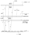
- FIG. 3 conceptually shows a state in which the identification medium 100 is observed through the left circular polarization filter 111.
- “right” indicates right circularly polarized light
- “left” indicates left circularly polarized light
- “other polarized light” is specified. It is a polarization component other than the right-handed circularly polarized light at the center wavelength.
- the cholesteric liquid crystal layer 102 selectively reflects the red right circularly polarized light 113.
- the selectively reflected red right circularly polarized light 113 is blocked by the left circular polarizing filter 111 and does not reach the observer side.
- right circularly polarized light other than red and mainly left circularly polarized light pass through the cholesteric liquid crystal layer 102 from the top to the bottom of the figure.
- the transmitted light is shown at a Other polarization.
- polarized light a is incident on the visible light all-reflection cholesteric liquid crystal layer 105, and the right circularly polarized light of the symbol b is reflected upward in the figure.
- This right circularly polarized light b is right circularly polarized light other than red, is blocked by the left circularly polarized light filter 111, and does not reach the observer.
- the left circularly polarized light (symbol “c”) included in the other polarized light “a” is transmitted through the visible light entire reflection cholesteric liquid crystal layer 105, reaches the display pattern 106, and is reflected there. At this time, the turning direction is reversed and reflected as right circularly polarized light d.
- the identification medium 100 when the identification medium 100 is observed through the left circular polarizing filter, the reflected light from the cholesteric liquid crystal layer 102 cannot be observed. That is, the hologram resulting from the hologram processing 103 cannot be observed.
- the image of the display pattern 106 can be visually recognized.
- an image recognition means using a camera that is, in image recognition using a camera, when imaging is performed through the left circular polarization filter 111, the hologram resulting from the hologram processing 103 is not acquired as an image, and the display of the display pattern 106 is acquired electronically as an image. Is done.
- a polarization component that can be transmitted through the visible light all-reflection cholesteric liquid crystal layer 105 is generated even when the polarization state is disturbed.
- This light passes through the cholesteric liquid crystal layer 102 and the left circularly polarizing filter 111 and is visually recognized by an observer.
- This light has the same image content as the observed light 114 and contributes to increasing the amount of the observed light 114.
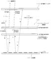
- FIG. 4 shows a case where the identification medium 100 is observed through the right circular polarization filter 115.
- the behavior of light rays in the identification medium 100 is the same as in FIG.
- the red right circularly polarized light 113 selectively reflected from the cholesteric liquid crystal layer 102 passes through the right circular polarizing filter 115 and is observed by the observer as the observation light 116. Therefore, a hologram image resulting from the hologram processing 103 can be observed through the right circular polarization filter 115.
- the light mainly composed of left circularly polarized light reflected from the display pattern 106 and transmitted through the cholesteric liquid crystal layer 102 in the upward direction in the figure is blocked by the right circularly polarizing filter 115 and cannot be observed. That is, when the identification medium 100 is viewed through the right circular polarization filter 115, the display pattern 106 cannot be visually recognized. Thus, when the identification medium 100 is viewed through the right circular polarization filter 115, the display pattern 106 cannot be visually recognized, while the hologram based on the hologram processing 103 applied to the cholesteric liquid crystal layer 102 can be clearly viewed.
- the identification medium 100 is observed through the left circular polarization filter of FIG. 3, only the display pattern 106 is visible. At this time, reflection is repeatedly performed on the lower surface side of the entire visible light reflection cholesteric liquid crystal layer 105, and reflected light is generated to increase the intensity of the observed light 114. Thereby, the brightness of the display pattern 106 becomes high.
- the display pattern 106 when viewed through the right circular polarizing filter 115, the display pattern 106 is not visible, and the hologram resulting from the hologram processing 103 of the cholesteric liquid crystal layer 102 is selectively visible.
- FIG. 5 is a schematic diagram showing an example of the appearance when the identification medium 100 is observed by switching the above-described circular polarizing filter.
- “GENUINE” is a print pattern of the display pattern 106
- “Security” is a hologram image resulting from the hologram processing 103.
- FIG. 5A shows the contents of an image observed when the identification medium 100 is observed through the left circular polarization filter 111 shown in FIG.
- the display pattern 106 “GENUINE” is selectively observed clearly.
- the hologram “Security” resulting from the hologram processing 103 of the cholesteric liquid crystal layer 102 cannot be seen.
- FIG. 5B shows the contents of an image observed when the identification medium 100 is observed through the right circular polarization filter 115 shown in FIG.
- the hologram “Security” resulting from the hologram processing 103 is selectively observed.
- the display pattern 106 “GENUINE” is not visible.
- FIG. 5C shows the contents of the image when the identification medium 100 is directly observed.
- the hologram “Security” resulting from the hologram processing 103 and the display pattern “GENUINE” are simultaneously observed.
- a protective layer 101 is formed on a base film (not shown), and a cholesteric liquid crystal layer 102 is further grown thereon. Then, hologram processing 103 by embossing is performed on the exposed surface of the cholesteric liquid crystal layer 102.
- Each of 105c is formed individually.
- the individually formed first cholesteric liquid crystal layer 105a, second cholesteric liquid crystal layer 105b, and third cholesteric liquid crystal layer 105c are stacked on the exposed surface of the cholesteric liquid crystal layer 102, and fixed with an adhesive.
- a display pattern 106 is formed on the back side of the exposed visible light all-reflection cholesteric liquid crystal layer 105 by an inkjet method or the like.
- the adhesive layer 107 is provided on the exposed surface of the visible light all-reflection cholesteric liquid crystal layer 105, and the separator 108 is attached to the exposed surface of the adhesive layer 107, whereby the medium 100 illustrated in FIG.
- a hard coat layer 101a is formed on a resin film (not shown) such as a PET film, and further a cholesteric liquid crystal layer 102 is formed thereon, Hologram processing 103 is performed. This is transferred to the COP layer 104, and a resin film (not shown) is peeled off to obtain a laminate of the COP layer 104 and the cholesteric liquid crystal layer 102.
- the visible light all-reflection cholesteric liquid crystal layer 105 is obtained by the method described above, and is adhered to the exposed surface of the COP layer 104.
- the identification medium 100 ′ is manufactured through the same process as the identification medium 100.
- the amount of reflected light from the display pattern 106 can be increased. In other words, since the reflected light from the display pattern 106 can be efficiently taken out of the identification medium 100, the amount of reflected light from the display pattern 106 can be increased. For this reason, the display pattern 106 looks brighter and the display pattern 106 looks clearer than when the circularly polarizing filter is used.
- the identification medium 100 ′ having the structure shown in FIG. 1B has an advantage that unauthorized reuse is difficult. That is, the cycloolefin polymer constituting the COP layer 104 has a chemical property that is very easy to deteriorate when it comes into contact with hydrocarbon solvents such as gasoline, kerosene, thinner, benzine, etc. It has a physical property that tends to cause breakage and wrinkles when a peeling force is applied.
- the structure in which the COP layer is sandwiched between the cholesteric liquid crystal layer 102 and the visible light all-reflective cholesteric liquid crystal layer 105 may be used when the identification medium 100 is illegally peeled off using a solvent, When the identification medium 100 is peeled off from the object, the layer structure of the identification medium 100 is destroyed and cannot be reused. This property is useful for preventing or making unauthorized reuse of the identification medium 100 difficult.
- the cycloolefin polymer constituting the COP layer 104 is inexpensive, but has physical properties such as streaks and cracks caused by physical contact from the outside (for example, by touching with the hand). Have. When this phenomenon occurs, there arises a problem that it is visually recognized.
- the COP layer 104 is sandwiched between the cholesteric liquid crystal layer 102 and the visible light all-reflection cholesteric liquid crystal layer 105 from the front and back. From the outside, and the problem that the above-described streaks and cracks occur in the COP layer 104 does not occur.
- FIG. 6A shows an identification medium 200 .
- the identification medium 200 has a structure in which a birefringent layer 110 is arranged between the visible light all-reflection cholesteric liquid crystal layer 105 and the display pattern 106 in the identification medium 100 of FIG.
- FIG. 6B shows an identification medium 200 ′ having a structure in which the COP layer 104 is sandwiched between the cholesteric liquid crystal layer 102 and the visible light entire reflection cholesteric liquid crystal layer 105 in the identification medium 200 as a modification. ing. Since the identification media 200 and 200 ′ are the same except for the COP layer 104, the identification media 200 in FIG. 6A will be described below.
- the birefringent layer 110 is incident on the visible light all-reflection cholesteric liquid crystal layer 105 from the observation surface side (upper side in FIG. 1) and passes through the visible light all-reflection cholesteric liquid crystal layer 105 (in this case, mainly left circularly polarized light). Component) and the polarization state of the reflected light from the display pattern 106 are disturbed. That is, the birefringence effect acts to disturb the polarization state of transmitted light. By disturbing the polarization state, a light component that can be transmitted through the visible light all-reflection cholesteric liquid crystal layer 105 from the bottom to the top in FIG. 3 is generated, and the reflected light from the display pattern 106 that is transmitted through the left circular polarization filter 111.
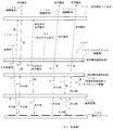
- FIG. 7 conceptually shows a state in which the identification medium 200 of FIG. 6 is observed through the left circular polarization filter 111.
- FIG. 7 what is described as "right” is the right circularly polarized light, what is described as “left” is the left circularly polarized light, that is described as “other polarization” specific
- a polarization component other than the right-handed circularly polarized light having the center wavelength and described as “others” is a light state in which the polarization state is disturbed and cannot be said to be a specific polarization state.
- the natural light entering the discrimination medium 200 the cholesteric liquid crystal layer 102 selectively reflects the red right circularly polarized light 113.
- the selectively reflected red right circularly polarized light 113 is blocked by the left circular polarizing filter 111 and does not reach the observer side.
- right circularly polarized light other than red and mainly left circularly polarized light pass through the cholesteric liquid crystal layer 102 from the top to the bottom of the figure.
- the transmitted light is shown at a Other polarization.
- polarized light a is incident on the visible light all-reflection cholesteric liquid crystal layer 105, and the right circularly polarized light of the symbol b is reflected upward in the figure.
- the right circularly polarized light with the symbol b is blocked by the left circular polarizing filter 111 and does not reach the observer.
- polarized light (symbol c) other than right circularly polarized light included in the polarized light a is incident on the birefringent layer 110, and the state of polarized light is disturbed by the birefringent effect. In this way, the light beam d in which the polarization state indicated by “others” is disturbed is incident on the display pattern 106 and reflected there.
- This reflected light is transmitted again through the birefringent layer 110 from the bottom to the top of the figure, and the state of polarization is further disturbed, and is incident on the lower surface side of the visible-light entire-reflection cholesteric liquid crystal layer 105 as a light beam with the symbol e.
- the light beam indicated by symbol e has a disordered polarization state and includes a left circularly polarized light component that can be transmitted through the visible light total reflection cholesteric liquid crystal layer 105.
- the component of the left circularly polarized light generated by the disorder of the changed state is transmitted through the visible light total reflection cholesteric liquid crystal layer 105 as the left circularly polarized light indicated by the symbol g.
- the left circularly polarized light indicated by the symbol g also passes through the cholesteric 102, reaches the left circularly polarized filter 111, passes therethrough, and is observed as the observed light 114a.
- the right circularly polarized light component in the light beam of the symbol e is reflected by the visible light all-reflection cholesteric liquid crystal layer 105 as the right circularly polarized light f and enters the birefringent layer 110.
- the birefringent layer 110 the right circularly polarized light f is disturbed in the polarization state and reflected on the display surface 106 as a light beam indicated by a symbol h.
- Reflected light j is generated by this reflection, and the reflected light j is further disturbed in the polarization state in the process of passing through the birefringent layer 110, and is incident on the lower surface of the visible light total reflection cholesteric liquid crystal layer 105 as a light beam indicated by a symbol k. To do.
- the polarization state of the light beam with the symbol k is also disordered, and the component of the left circularly polarized light that can be transmitted through the visible light all-reflection cholesteric liquid crystal layer 105 is the left circularly polarized light m. Then, the visible light entire reflection cholesteric liquid crystal layer 105 is transmitted upward in the figure.
- the right circularly polarized light indicated by reference numeral 1 included in the reference numeral k is reflected again in the direction of the display pattern 106.
- the left circularly polarized light m passes through the cholesteric liquid crystal layer 102 and further passes through the left circularly polarized filter 111 and is visually recognized by the observer as the observed light 114b.
- Right circular polarization l the state of polarization is disturbed in the course of passing through the birefringent layer 110, via label f ⁇ h ⁇ j ⁇ k similar pathway, the observed light part of the component as a left-circularly polarized light q 114c, and the component of the right circularly polarized light generated by the polarization disturbance is reflected again to the display pattern 106 side as the right circularly polarized light p.
- Left-hand circularly polarized light 114a, 114b, and 114c is reflected light from the display pattern 106 and includes image information of the display pattern 106. Further, the light is transmitted without being reflected or diffracted by the hologram of the cholesteric liquid crystal layer 102, and does not include hologram image information resulting from the hologram processing 103. For this reason, the display pattern 106 looks clear and the hologram of the cholesteric liquid crystal layer 102 cannot be seen. In addition, the images of the display pattern 106 are observed more brightly and clearly by combining the light to be observed 114a, 114b, and 114c. This effect is also obtained for the light beam with the sign p.
- FIG. 8 shows a case where the identification medium 200 is observed through the right circular polarization filter 115.
- the behavior of light inside the identification medium 200 is the same as in FIG.
- the left circularly polarized light reflected from the identification medium 200 is blocked by the right circular polarizing filter 115 and is not observed.
- the right circularly polarized light 113 reflected from the cholesteric liquid crystal layer 102 passes through the right circularly polarized filter 115 and is observed by the observer as the observed light 117.
- the display pattern 106 is not observed, and a hologram based on the hologram processing 103 is selectively observed.
- the identification medium 200 when the identification medium 200 is observed through the left circular polarizing filter, only the display pattern 106 is visible. At this time, reflection is repeatedly performed on the lower surface side of the visible light total reflection cholesteric liquid crystal layer 105, and further, there is generated reflected light that increases the intensity of the observed light 114 a by the birefringence effect in the birefringent layer 110.
- the observed contents described above are the same whether the circularly polarizing filters 111 and 114 are separated from the identification medium or in close contact with the identification medium. Moreover, cholesteric liquid crystal, changing the viewing angle, but the color shifting effect of color is shifted to the shorter wavelength side is observed, even in the identification medium 200 and 200 ', by changing the viewing angle (e.g., the identification medium thing) tilting, can be observed color shift.
- FIG. 9A shows an identification medium 300 of the embodiment.
- the identification medium 300 has a structure in which a protective layer 101, a cholesteric liquid crystal layer 102 on which a hologram processing 103 has been performed, a visible light entire reflection cholesteric liquid crystal layer 105, and an adhesive layer 601 are arranged from the observation side.
- FIG. 9 shows an identification object (article) 603 on which a display pattern 602 is further formed.
- the reference numerals common to FIG. 1 are the same as those described in relation to FIG. In this example, a state where the identification medium 300 is attached to the object 603 by the adhesive force of the adhesive layer 601 is shown.
- FIG. 9 shows an identification medium 300 of the embodiment.
- the identification medium 300 has a structure in which a protective layer 101, a cholesteric liquid crystal layer 102 on which a hologram processing 103 has been performed, a visible light entire reflection cholesteric liquid crystal layer 105, and an adhesive layer 601 are arranged from the observation side.
- FIG. 9B shows an identification medium 300 ′ having a structure in which a COP layer 104 is interposed between the cholesteric liquid crystal layer 102 and the visible light whole-reflection cholesteric liquid crystal layer 105 in the identification medium 300 shown in FIG. 9A. It is shown.
- the adhesive layer 601 is an optically transparent adhesive.
- the display pattern 602 is a print pattern formed on the surface of the object 601, and is a code display such as various patterns, characters, logos, patterns, and barcodes.
- the optical property of the identification medium 300 is the same as that of the identification medium 100 of FIG.
- the identification medium 300 differs from the identification medium 100 of FIG. 1 in that the identification medium 100 includes a display pattern 106 that is a basis of an image used for identification, whereas the identification medium 300 uses an image used for identification as an image used for identification.
- the display pattern 602 on the object 603 side is used.
- a separator (release paper) (not shown) is attached to the back side of the adhesive layer 601 in a state where it is not attached to the object, that is, in a state where the identification medium 300 is not used. At the time of use, this separator is peeled off from the back surface of the adhesive layer 601, and the identification medium 300 is attached to the object by the adhesive function of the adhesive layer 601. An example of this state is shown in FIG. Further, in the structure shown in FIG. 9, it is possible to provide a birefringent layer on the lower surface side of the visible light all-reflection cholesteric liquid crystal layer 105 and obtain an optical function similar to that described with reference to FIGS. .
- FIG. 10 shows an identification medium 400.
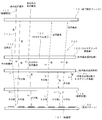
- the identification medium 400 has a structure in which a protective layer 101, an optically anisotropic layer 301, a visible light all-reflection cholesteric liquid crystal layer 105, an adhesive layer 107, and a separator 108 are laminated from the observation side surface.
- a protective layer 101 an optically anisotropic layer 301, a visible light all-reflection cholesteric liquid crystal layer 105, an adhesive layer 107, and a separator 108 are laminated from the observation side surface.
- the same reference numerals as those in FIG. 1 are the same as those in FIG.
- the optically anisotropic layer 301 is made of an oriented polymer material having birefringence, and is made of a material that undergoes a polymerization reaction of the polymer when exposed to light and whose orientation state is determined.
- the polymer in the optically anisotropic layer has an unreacted reactive group. Unreacted reactive groups react upon exposure to cause cross-linking of the polymer chains, and the degree of cross-linking of the polymer chains varies depending on exposure under different exposure conditions. As a result, the retardation value changes, resulting in a birefringence pattern. It is formed.
- the optically anisotropic layer 301 may have a retardation of 5 nm or more at 20 ° C., preferably 10 nm or more and 10,000 nm or less, and most preferably 20 nm or more and 2000 nm or less.
- a solution containing a liquid crystal compound having at least one reactive group is applied and dried to form a liquid crystal phase, and then irradiated with ionizing radiation to be polymerized and fixed. Adopt the method to do.
- This method is described in JP2009-175208A.
- a method of stretching a layer in which a monomer having at least two or more reactive groups is polymerized and immobilized, a reactive group is formed using a coupling agent in a layer made of a polymer.
- the optically anisotropic layer of the present invention may be formed by transfer.
- the thickness of the optically anisotropic layer 301 is preferably 0.1 to 20 ⁇ m, and more preferably 0.5 to 10 ⁇ m.
- a composition containing a liquid crystal compound (for example, a coating solution) is applied onto an easily peelable layer that has been subjected to an alignment treatment.
- a liquid crystal compound containing a rod-like liquid crystal, a horizontal alignment agent, a cationic photopolymerization initiator, a polymerization controller, and methyl ethyl ketone is used.
- this orientation state is fixed by irradiation of ionizing radiation.
- the alignment state of the aligned liquid crystal compound is fixed by a photopolymerization reaction.
- the irradiation energy for light irradiation is selected from 25 to 800 mJ / cm 2 .
- As the irradiation wavelength ultraviolet light having a peak at 250 to 450 nm is used.
- the region D is a simple light transmission layer that does not emit light and does not produce a birefringence effect.
- the above phase difference is adjusted by changing the light amount (exposure amount) of the irradiated light. Thereafter, by applying heat treatment at a temperature of 200 ° C., the state of fixation of the alignment state according to the amount of light irradiated is determined, thereby obtaining the optically anisotropic layer 301 partially different in birefringence state. . If light is not applied, the orientation state is disturbed during heat treatment, and the birefringence of the region disappears (a simple light transmission layer).
- the above heat treatment can be performed at a temperature selected from the range of 50 ° C to 400 ° C.
- an optically anisotropic layer 301 is obtained in which there is a difference in the refractive index in the orthogonal direction in the plane, and the state of the difference is different in the regions A, B, and C shown in FIG.
- the phase difference generated in these regions is set so that the regions A, B, and C appear to have different colors during observation using the circular polarizing filter.
- the region D is formed as a simple light transmission region having no refractive index anisotropy.
- the optically anisotropic layer 301 When the optically anisotropic layer 301 is obtained, it is peeled off from an easy peeling layer (not shown) and fixed to the protective layer 101. Thereafter, lamination with the visible light all-reflection cholesteric liquid crystal layer 105, formation of the adhesive layer 107, and attachment of the separator 108 are performed to obtain the identification medium 400 shown in FIG.
- the fixing of the identification medium 400 to the object is performed by removing the separator 108 and bringing the adhesive layer 107 into contact with the object. This is the same as the identification medium 100 of FIG. Note that the turning direction of the circularly polarized light selectively reflected by the visible light all-reflection cholesteric liquid crystal layer 105 is not limited to the right turn but may be the left turn.
- the reason why the reflected light from the areas A, B, and C looks different colors is as follows.
- the phase difference component of the polarization orthogonal with an optical anisotropic layer within 301 occurs, since this occurs the phase difference is wavelength dependent, when focusing on a certain polarization components, optical A color centered on the wavelength corresponding to the phase difference generated in the anisotropic layer 301 can be seen. For this reason, different colors are observed depending on the difference in the generated phase difference.
- the regions A, B, and C are set to have different phase differences, the regions A, B, and C have different colors in the observation through the circular polarization filter. appear.
- the regions A, B, and C appear to have different colors from those when the right circular polarization filter is used. This is because the polarization component extracted by the circular polarization filter is different from the case where the right circular polarization filter is used. Also in this case, each of the regions A, B, and C looks different colors. Further, since the right circularly polarized reflected light from the region D is blocked by the left circular polarizing filter, the reflected light from the visible light all-reflection cholesteric liquid crystal layer 105 is not visible, and the background of the visible light all-reflection cholesteric liquid crystal layer 105 is visible. The adhesive layer 107 is visible. Here, if the adhesive layer 107 is colored, the color is visible in the region D, and if the adhesive layer 107 is transparent, the surface of the lower layer of the adhesive layer 107 is visible in the region D.
- the optically anisotropic layer including a plurality of regions having different optical anisotropy states and the visible light total reflection cholesteric liquid crystal layer are arranged from the observed side. It has a structure.
- the identification medium 500 When the identification medium 500 is observed from the upper direction of the drawing through the right circular polarizing filter, for example, red right circular polarized light reflected from the cholesteric liquid crystal layer 102 is observed. For this reason, the hologram resulting from the hologram processing 103 is observed.
- the identification medium 500 When the identification medium 500 is observed through the left circular polarizing filter, the reflected light from the cholesteric liquid crystal layer 102 cannot be observed.
- the right circularly polarized light reflected from the cholesteric liquid crystal layer 105 that reflects the entire visible light region is inverted by the ⁇ / 2 plate 401 to become left circularly polarized light, and thus passes through the cholesteric liquid crystal layer 102 as it is.
- Reflected light from the reflective cholesteric liquid crystal layer 105 can be observed. Since this reflected light is left circularly polarized light and is observed as light in the entire visible light range, for example, reflected light having a metallic luster is observed in a state where the hologram of the cholesteric liquid crystal 102 is not visible.
- the ⁇ / 2 plate 401 can be omitted when the rotation direction of the circularly polarized light reflected from the visible light whole reflection cholesteric liquid crystal layer 105 is set to the left rotation. It is also possible to selective reflection wavelength of the cholesteric liquid crystal layer 102 and the other color other than red, also be also set to the turning direction of the circularly polarized light is selectively reflected and left turn.
- FIG. 12 shows, from the observed side, a cholesteric liquid crystal layer that has been subjected to hologram processing, a ⁇ / 2 plate, and a visible light that selectively reflects circularly polarized light in the same turning direction as the cholesteric liquid crystal layer. and an optical entire reflecting cholesteric liquid crystal layer.
- the turning direction of the circularly polarized light reflected from the visible light all-reflection cholesteric liquid crystal layer is opposite to that of the cholesteric liquid crystal layer.
- the present invention can be used for a technique for identifying authenticity.
Landscapes
- Physics & Mathematics (AREA)
- Chemical & Material Sciences (AREA)
- Engineering & Computer Science (AREA)
- General Physics & Mathematics (AREA)
- Nonlinear Science (AREA)
- Crystallography & Structural Chemistry (AREA)
- Theoretical Computer Science (AREA)
- Optics & Photonics (AREA)
- Mathematical Physics (AREA)
- Computer Security & Cryptography (AREA)
- Toxicology (AREA)
- Health & Medical Sciences (AREA)
- General Health & Medical Sciences (AREA)
- Manufacturing & Machinery (AREA)
- General Chemical & Material Sciences (AREA)
- Chemical Kinetics & Catalysis (AREA)
- Dispersion Chemistry (AREA)
- Polarising Elements (AREA)
- Credit Cards Or The Like (AREA)
- Holo Graphy (AREA)
- Business, Economics & Management (AREA)
- Accounting & Taxation (AREA)
- Finance (AREA)
Abstract
La présente invention se rapporte à un support distinctif avec lequel il est possible d'observer un net changement d'image avec une structure qui peut être obtenue à peu de frais. Le support distinctif présente une structure dans laquelle sont positionnés depuis le côté où l'observation est effectuée : une couche de cristaux liquides cholestériques (102) sur laquelle un travail holographique est réalisé et qui réfléchit de manière sélective la lumière polarisée de manière circulaire ayant une longueur d'onde centrale spécifiée dans une direction de rotation spécifiée ; une couche de cristaux liquides cholestériques réfléchissante (105) dans toute la région de la lumière visible qui présente une caractéristique de réflexion qui est équivalente à celle observée lors de la réflexion de la lumière de toute la région de la lumière visible et qui réfléchit la lumière polarisée de manière circulaire dans la même direction de rotation que la lumière polarisée de manière circulaire qui est réfléchie depuis la couche de cristaux liquides cholestériques (102) ; et un motif d'affichage (106) qui est traité comme ayant un contenu d'affichage spécifié.
Priority Applications (3)
| Application Number | Priority Date | Filing Date | Title |
|---|---|---|---|
| US14/006,038 US9298036B2 (en) | 2011-03-18 | 2012-03-08 | Identification medium |
| CN201280014299.5A CN103562757B (zh) | 2011-03-18 | 2012-03-08 | 识别介质 |
| EP12760512.9A EP2687879B1 (fr) | 2011-03-18 | 2012-03-08 | Support distinctif |
Applications Claiming Priority (2)
| Application Number | Priority Date | Filing Date | Title |
|---|---|---|---|
| JP2011061184A JP5647047B2 (ja) | 2011-03-18 | 2011-03-18 | 識別媒体 |
| JP2011-061184 | 2011-03-18 |
Publications (1)
| Publication Number | Publication Date |
|---|---|
| WO2012128057A1 true WO2012128057A1 (fr) | 2012-09-27 |
Family
ID=46879211
Family Applications (1)
| Application Number | Title | Priority Date | Filing Date |
|---|---|---|---|
| PCT/JP2012/055977 Ceased WO2012128057A1 (fr) | 2011-03-18 | 2012-03-08 | Support distinctif |
Country Status (5)
| Country | Link |
|---|---|
| US (1) | US9298036B2 (fr) |
| EP (1) | EP2687879B1 (fr) |
| JP (1) | JP5647047B2 (fr) |
| CN (1) | CN103562757B (fr) |
| WO (1) | WO2012128057A1 (fr) |
Cited By (2)
| Publication number | Priority date | Publication date | Assignee | Title |
|---|---|---|---|---|
| CN105190654A (zh) * | 2013-03-21 | 2015-12-23 | 日本发条株式会社 | 识别介质、码信息的读取方法、码信息的读取装置、识别介质的制造方法以及识别介质的制造装置 |
| WO2022168690A1 (fr) * | 2021-02-05 | 2022-08-11 | 日本ゼオン株式会社 | Stratifié optique ainsi que procédé de jugement d'authenticité de celui-ci, et article |
Families Citing this family (16)
| Publication number | Priority date | Publication date | Assignee | Title |
|---|---|---|---|---|
| WO2012137550A1 (fr) * | 2011-04-01 | 2012-10-11 | 日本発條株式会社 | Milieu de distinction |
| US9243169B2 (en) * | 2013-05-16 | 2016-01-26 | Sicpa Holding Sa | Security laminate |
| WO2015025909A1 (fr) * | 2013-08-21 | 2015-02-26 | 富士フイルム株式会社 | Filtre polarisant circulaire et son application |
| WO2016088708A1 (fr) * | 2014-12-01 | 2016-06-09 | 富士フイルム株式会社 | Miroir ayant une fonction d'affichage d'image |
| JP6314249B2 (ja) * | 2014-12-01 | 2018-04-18 | 富士フイルム株式会社 | 画像表示機能付きミラー |
| JP6458658B2 (ja) * | 2015-06-15 | 2019-01-30 | 凸版印刷株式会社 | 透かし用紙 |
| DE102016003967A1 (de) * | 2016-04-01 | 2017-10-05 | Giesecke+Devrient Currency Technology Gmbh | Datenträger mit Aufdruck |
| DE102017116736B3 (de) * | 2017-07-25 | 2018-12-13 | Infineon Technologies Ag | Chipkartenmodul, verfahren zum herstellen eines chipkartenmoduls, chipkarte und verfahren zum prüfen eines chipkartenmoduls |
| EP3805824B1 (fr) * | 2018-05-31 | 2024-10-09 | Zeon Corporation | Support d'identification, et procédé de détermination de l'authenticité d'un support d'identification |
| JP7396275B2 (ja) * | 2018-06-29 | 2023-12-12 | 日本ゼオン株式会社 | 識別媒体、真正性判定方法、及び物品 |
| US11988856B2 (en) * | 2019-06-26 | 2024-05-21 | Zeon Corporation | Display medium, authenticity determination method, and article including display medium |
| WO2021020024A1 (fr) | 2019-07-31 | 2021-02-04 | 日本ゼオン株式会社 | Support d'affichage, produit d'affichage et ensemble d'affichage |
| WO2021065484A1 (fr) * | 2019-09-30 | 2021-04-08 | 日本ゼオン株式会社 | Support d'affichage, produit d'affichage et ensemble d'affichage |
| KR102441227B1 (ko) * | 2020-05-13 | 2022-09-07 | 엔비에스티(주) | 콜레스테릭 액정 표시층을 포함하는 연포장재 |
| JP7552479B2 (ja) * | 2021-03-30 | 2024-09-18 | 日本ゼオン株式会社 | 識別媒体、製造方法、物品、及び識別媒体の使用方法 |
| CN114779520A (zh) * | 2022-05-25 | 2022-07-22 | 深圳蓝鲸世纪科技有限公司 | 光学系统和显示设备 |
Citations (7)
| Publication number | Priority date | Publication date | Assignee | Title |
|---|---|---|---|---|
| JP3373374B2 (ja) | 1995-11-09 | 2003-02-04 | 日東電工株式会社 | 偏光素子及び楕円偏光素子 |
| JP2004338257A (ja) * | 2003-05-16 | 2004-12-02 | Nhk Spring Co Ltd | 対象物の識別媒体及び識別方法 |
| JP2005134490A (ja) * | 2003-10-28 | 2005-05-26 | Nhk Spring Co Ltd | 識別媒体、識別媒体の識別方法、識別対象物品および識別装置 |
| JP2007069486A (ja) * | 2005-09-07 | 2007-03-22 | Dainippon Printing Co Ltd | 体積型ホログラム付きコレステリック液晶媒体の製造方法 |
| JP2009172798A (ja) | 2008-01-22 | 2009-08-06 | Nhk Spring Co Ltd | 識別媒体およびその製造方法 |
| JP2009175208A (ja) | 2008-01-22 | 2009-08-06 | Fujifilm Corp | 複屈折パターンを有する物品の製造方法 |
| JP2009216722A (ja) * | 2008-03-06 | 2009-09-24 | Toppan Printing Co Ltd | セキュリティデバイス及びラベル付き物品 |
Family Cites Families (7)
| Publication number | Priority date | Publication date | Assignee | Title |
|---|---|---|---|---|
| JP4335352B2 (ja) | 1999-03-05 | 2009-09-30 | 大日本印刷株式会社 | 偽造防止体及び偽造判別方法 |
| DE102004021246A1 (de) | 2004-04-30 | 2005-11-24 | Giesecke & Devrient Gmbh | Sicherheitselement und Verfahren zu seiner Herstellung |
| US20080138543A1 (en) | 2004-12-24 | 2008-06-12 | Nhk Spring Co., Ltd. | Identification Medium, Article Equipped With Identification Medium, Identifying Method And Device |
| JP4866129B2 (ja) * | 2006-04-03 | 2012-02-01 | 日本発條株式会社 | 識別媒体、識別方法および識別装置 |
| JP4959304B2 (ja) * | 2006-11-22 | 2012-06-20 | 日本発條株式会社 | 識別媒体、識別方法および識別装置 |
| JP5231163B2 (ja) * | 2008-10-14 | 2013-07-10 | 日本発條株式会社 | 識別媒体および物品 |
| KR101798584B1 (ko) * | 2010-06-24 | 2017-11-17 | 삼성전자주식회사 | 광학 보상 필름 및 그 제조 방법과 상기 광학 보상 필름을 구비하는 액정 표시 장치 |
-
2011
- 2011-03-18 JP JP2011061184A patent/JP5647047B2/ja active Active
-
2012
- 2012-03-08 EP EP12760512.9A patent/EP2687879B1/fr active Active
- 2012-03-08 WO PCT/JP2012/055977 patent/WO2012128057A1/fr not_active Ceased
- 2012-03-08 US US14/006,038 patent/US9298036B2/en active Active
- 2012-03-08 CN CN201280014299.5A patent/CN103562757B/zh active Active
Patent Citations (8)
| Publication number | Priority date | Publication date | Assignee | Title |
|---|---|---|---|---|
| JP3373374B2 (ja) | 1995-11-09 | 2003-02-04 | 日東電工株式会社 | 偏光素子及び楕円偏光素子 |
| JP2004338257A (ja) * | 2003-05-16 | 2004-12-02 | Nhk Spring Co Ltd | 対象物の識別媒体及び識別方法 |
| JP4392826B2 (ja) | 2003-05-16 | 2010-01-06 | 日本発條株式会社 | 対象物の識別媒体及び識別方法 |
| JP2005134490A (ja) * | 2003-10-28 | 2005-05-26 | Nhk Spring Co Ltd | 識別媒体、識別媒体の識別方法、識別対象物品および識別装置 |
| JP2007069486A (ja) * | 2005-09-07 | 2007-03-22 | Dainippon Printing Co Ltd | 体積型ホログラム付きコレステリック液晶媒体の製造方法 |
| JP2009172798A (ja) | 2008-01-22 | 2009-08-06 | Nhk Spring Co Ltd | 識別媒体およびその製造方法 |
| JP2009175208A (ja) | 2008-01-22 | 2009-08-06 | Fujifilm Corp | 複屈折パターンを有する物品の製造方法 |
| JP2009216722A (ja) * | 2008-03-06 | 2009-09-24 | Toppan Printing Co Ltd | セキュリティデバイス及びラベル付き物品 |
Cited By (6)
| Publication number | Priority date | Publication date | Assignee | Title |
|---|---|---|---|---|
| CN105190654A (zh) * | 2013-03-21 | 2015-12-23 | 日本发条株式会社 | 识别介质、码信息的读取方法、码信息的读取装置、识别介质的制造方法以及识别介质的制造装置 |
| EP2977935A4 (fr) * | 2013-03-21 | 2016-11-23 | Nhk Spring Co Ltd | Support d'identification, procédé de lecture d'informations de code, dispositif de lecture d'informations de code, procédé de fabrication de support d'identification et dispositif de fabrication de support d'identification |
| CN105190654B (zh) * | 2013-03-21 | 2019-11-05 | 日本发条株式会社 | 识别介质、码信息的读取方法、码信息的读取装置、识别介质的制造方法以及识别介质的制造装置 |
| WO2022168690A1 (fr) * | 2021-02-05 | 2022-08-11 | 日本ゼオン株式会社 | Stratifié optique ainsi que procédé de jugement d'authenticité de celui-ci, et article |
| JPWO2022168690A1 (fr) * | 2021-02-05 | 2022-08-11 | ||
| CN116829994A (zh) * | 2021-02-05 | 2023-09-29 | 日本瑞翁株式会社 | 光学层叠体及其真实性的判断方法、以及物品 |
Also Published As
| Publication number | Publication date |
|---|---|
| EP2687879B1 (fr) | 2017-08-30 |
| CN103562757A (zh) | 2014-02-05 |
| JP5647047B2 (ja) | 2014-12-24 |
| EP2687879A1 (fr) | 2014-01-22 |
| US9298036B2 (en) | 2016-03-29 |
| JP2012198316A (ja) | 2012-10-18 |
| EP2687879A4 (fr) | 2014-10-01 |
| US20140022493A1 (en) | 2014-01-23 |
| CN103562757B (zh) | 2016-11-09 |
Similar Documents
| Publication | Publication Date | Title |
|---|---|---|
| JP5647047B2 (ja) | 識別媒体 | |
| JP4875003B2 (ja) | 識別媒体およびその製造方法 | |
| KR101392614B1 (ko) | 식별 매체 및 그 식별 방법 | |
| KR101531439B1 (ko) | 식별 매체 및 그 식별 방법 | |
| CN101501537B (zh) | 识别介质、识别介质的制造方法、物品和识别介质的识别方法 | |
| JP2005134490A (ja) | 識別媒体、識別媒体の識別方法、識別対象物品および識別装置 | |
| WO2004102234A1 (fr) | Support d'identification d'objet et procede d'identification | |
| WO2006068180A1 (fr) | Moyen d'identification, article dote du moyen d'identification, procede et dispositif d'identification | |
| JP2015089638A (ja) | 偽造防止用デバイスおよびその製造方法 | |
| JP6179086B2 (ja) | 偽造防止媒体、それを用いた偽造防止ステッカーおよび偽造防止物品 | |
| JP4978403B2 (ja) | 光学素子、ラベル付き物品、光学キット及び判別方法 | |
| JP2005022292A (ja) | 対象物の識別構造およびその構造が設けられた対象物 | |
| JP2011126199A (ja) | 画像表示体、ブランク媒体及び個人認証媒体 | |
| JP6927886B2 (ja) | 光学セキュリティ装置 | |
| WO2017204168A1 (fr) | Support empêchant la contrefaçon | |
| JP5811568B2 (ja) | 偽造防止媒体 | |
| JP5245473B2 (ja) | セキュリティデバイス及びラベル付き物品 | |
| CN113665206B (zh) | 包括胆甾相液晶显示层的软包装材料 | |
| JP2013064882A (ja) | 情報記録媒体 | |
| JP2008139509A (ja) | 積層体、粘着ラベル、記録媒体、ラベル付き物品及び判別方法 | |
| JP2014021152A (ja) | 識別媒体および識別方法 |
Legal Events
| Date | Code | Title | Description |
|---|---|---|---|
| 121 | Ep: the epo has been informed by wipo that ep was designated in this application |
Ref document number: 12760512 Country of ref document: EP Kind code of ref document: A1 |
|
| NENP | Non-entry into the national phase |
Ref country code: DE |
|
| WWE | Wipo information: entry into national phase |
Ref document number: 14006038 Country of ref document: US |
|
| REEP | Request for entry into the european phase |
Ref document number: 2012760512 Country of ref document: EP |
|
| WWE | Wipo information: entry into national phase |
Ref document number: 2012760512 Country of ref document: EP |