WO2012128059A1 - Capteur de couple - Google Patents
Capteur de couple Download PDFInfo
- Publication number
- WO2012128059A1 WO2012128059A1 PCT/JP2012/056000 JP2012056000W WO2012128059A1 WO 2012128059 A1 WO2012128059 A1 WO 2012128059A1 JP 2012056000 W JP2012056000 W JP 2012056000W WO 2012128059 A1 WO2012128059 A1 WO 2012128059A1
- Authority
- WO
- WIPO (PCT)
- Prior art keywords
- ring magnet
- torque sensor
- back yoke
- protrusion
- magnetic
- Prior art date
- Legal status (The legal status is an assumption and is not a legal conclusion. Google has not performed a legal analysis and makes no representation as to the accuracy of the status listed.)
- Ceased
Links
Images


Classifications
-
- G—PHYSICS
- G01—MEASURING; TESTING
- G01L—MEASURING FORCE, STRESS, TORQUE, WORK, MECHANICAL POWER, MECHANICAL EFFICIENCY, OR FLUID PRESSURE
- G01L3/00—Measuring torque, work, mechanical power, or mechanical efficiency, in general
- G01L3/02—Rotary-transmission dynamometers
- G01L3/04—Rotary-transmission dynamometers wherein the torque-transmitting element comprises a torsionally-flexible shaft
- G01L3/10—Rotary-transmission dynamometers wherein the torque-transmitting element comprises a torsionally-flexible shaft involving electric or magnetic means for indicating
- G01L3/101—Rotary-transmission dynamometers wherein the torque-transmitting element comprises a torsionally-flexible shaft involving electric or magnetic means for indicating involving magnetic or electromagnetic means
- G01L3/104—Rotary-transmission dynamometers wherein the torque-transmitting element comprises a torsionally-flexible shaft involving electric or magnetic means for indicating involving magnetic or electromagnetic means involving permanent magnets
Definitions
- the present invention relates to a torque sensor that detects a torque acting on a shaft in accordance with a magnetic flux density guided from a magnet.
- JP 2007-240696A discloses a non-contact type torque sensor that detects a steering torque acting on a steering shaft by a magnetic force.
- the torque sensor includes a torsion bar that transmits a steering torque between an input shaft and an output shaft that are arranged on the same axis, a magnetism generating unit that is fixed to the input shaft, and a rotating magnetic circuit unit that is fixed to the output shaft. And a fixed magnetic circuit part fixed to the housing, and a magnetic sensor for detecting a magnetic flux density guided to the fixed magnetic circuit part.
- the magnetism generating unit includes a back yoke fixed to the input shaft and a ring magnet fixed to the back yoke via an adhesive.
- the present invention has been made in view of the above problems, and a torque sensor that can prevent a ring magnet from falling off even when a poor adhesion between the ring magnet and the back yoke occurs.
- the purpose is to provide.
- a torque sensor that detects torque acting on a torsion bar that connects a first shaft and a second shaft that are rotatably supported in a housing, and is fixed to the first shaft.
- a magnetic detector for detecting a magnetic flux density guided to the fixed magnetic circuit section through the circuit section, and the magnetism generating section projects from a back yoke fitted to the first shaft and an end surface of the back yoke.
- An annular ring magnet provided on an end surface of the back yoke so as to have a predetermined gap between the annular protrusion formed and the protrusion; and And location, a torque sensor and a holding mechanism for holding the ring magnet to the back yoke is provided.
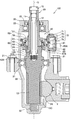
- FIG. 1 is a longitudinal sectional view of a power steering apparatus according to a first embodiment of the present invention.
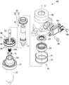
- FIG. 2 is an exploded perspective view of the power steering apparatus with the lower housing removed.
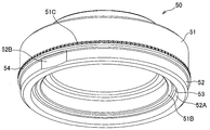
- FIG. 3A is a perspective view of a magnetism generator of the torque sensor according to the first embodiment.
- FIG. 3B is a bottom view of the magnetism generator of the torque sensor according to the first embodiment.
- FIG. 4 is a perspective view of the rotating magnetic circuit unit of the torque sensor according to the first embodiment.
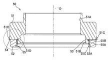
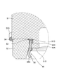
- FIG. 5A is a longitudinal sectional view of the magnetism generating portion.
- FIG. 5B is an enlarged view of the magnetism generator in the broken line region of FIG. 5A.
- FIG. 6 is a vertical cross-sectional perspective view of the magnetism generator.
- FIG. 7A is a perspective view of a magnetism generator of the torque sensor according to the second embodiment.
- FIG. 7B is an exploded perspective view of a magnetism generator of the torque sensor according to the second embodiment.
- FIG. 8 is a bottom view of the magnetism generator of the torque sensor according to the second embodiment.
- FIG. 9A is a longitudinal cross-sectional view of the magnetism generating part in the AA plane of FIG.
- FIG. 9B is a vertical cross-sectional view of the magnetism generator in the BB plane of FIG.
- FIG. 10 is an enlarged view of the magnetism generator in the broken line region of FIG. 9B.
- a vehicle power steering apparatus 100 according to a first embodiment of the present invention will be described with reference to FIGS.
- the power steering apparatus 100 includes a steering shaft 10 that is linked to a steering wheel and a rack shaft 2 that is linked to a wheel. It is a device that moves and steers the wheel.
- Steering shaft 10 is a shaft member that is supported by upper housing 20 and lower housing 30 that are connected by bolts 21.
- the steering shaft 10 includes an input shaft 11 as a first shaft, a torsion bar 12, and an output shaft 13 as a second shaft.
- the input shaft 11 is rotatably supported by the upper housing 20 via a rolling bearing 22.
- a dust seal 23 seals between the input shaft 11 and the upper housing 20.
- the dust seal 23 is disposed above the rolling bearing 22.
- the output shaft 13 is rotatably supported by a rolling bearing 31 sandwiched between the lower end portion of the upper housing 20 and the upper end portion of the lower housing 30 and a sliding bearing 32 installed at the lower end portion of the lower housing 30.
- a housing chamber 13A capable of housing the lower end portion of the input shaft 11 is formed at the upper end portion of the output shaft 13.
- a sliding bearing 14 is interposed between the inner peripheral surface of the storage chamber 13 ⁇ / b> A of the output shaft 13 and the outer peripheral surface of the lower end portion of the input shaft 11.
- the input shaft 11 is formed in a cylindrical shape, and a torsion bar 12 is accommodated coaxially inside the input shaft 11.
- the upper end portion of the torsion bar 12 is connected to the upper end portion of the input shaft 11 via the pin 15.
- the lower end portion of the torsion bar 12 protrudes downward from the lower end opening portion of the input shaft 11.
- a serration 12 ⁇ / b> A is formed on the outer peripheral surface of the lower end portion of the torsion bar 12.
- the lower end of the torsion bar 12 is connected to an engagement hole 13B formed in the bottom of the storage chamber 13A via a serration 12A.
- the torsion bar 12 transmits a steering torque input to the input shaft 11 to the output shaft 13 and twists and deforms about the rotation axis O according to the torque.
- the output shaft 13 includes a gear 13C on the outer peripheral surface near the lower end.
- a gear 13 ⁇ / b> C of the output shaft 13 meshes with a rack gear 2 ⁇ / b> A formed on the rack shaft 2.
- the rack shaft 2 moves in the axial direction, and the wheels are steered.
- the power steering apparatus 100 includes a non-contact type torque sensor 40 that detects a steering torque that acts on the torsion bar 12 as an assist mechanism that supplementarily applies a steering torque, and a rack shaft 2 that corresponds to the detected steering torque. And an electric motor for applying steering assist torque.
- the torque sensor 40 includes a magnetism generating unit 50 that rotates with the input shaft 11, a rotating magnetic circuit unit 60 that rotates with the output shaft 13, a fixed magnetic circuit unit 70 that is fixed to the upper housing 20, and a fixed magnetic circuit unit 70. And a magnetic sensor 81 for detecting the guided magnetic flux density.
- the torque sensor 40 detects the steering torque acting on the torsion bar 12 based on the output of the magnetic sensor 81.
- the torque sensor 40 may have a configuration in which the output shaft 13 is provided with the magnetism generating unit 50 and the input shaft 11 is provided with the rotating magnetic circuit unit 60.
- the magnetism generator 50 includes an annular back yoke 51 press-fitted into the input shaft 11 and an annular back yoke 51 fixed to the lower end surface of the back yoke 51 via an adhesive.
- a ring magnet 52 is shown in FIG. 1, FIG. 3A and FIG. 3B.
- the ring magnet 52 is an annular permanent magnet.
- the ring magnet 52 is a multipolar magnet formed by magnetizing a hard magnetic material in the direction of the rotation axis O of the input shaft 11. As shown in FIG. 3B, twelve magnetic poles are formed at equal intervals in the circumferential direction on the ring magnet 52. That is, on the upper end surface and the lower end surface of the ring magnet 52, six N poles and six S poles are alternately arranged in the circumferential direction.
- the number of magnetic poles provided in the ring magnet 52 is not limited to 12 and can be arbitrarily set as necessary.
- the back yoke 51 is an annular member formed of a soft magnetic material.
- a ring magnet 52 is fixed to the lower end surface of the back yoke 51.
- the back yoke 51 has a function as a yoke that guides magnetic flux by connecting adjacent magnetic poles of the ring magnet 52, and concentrates the magnetic force on the lower magnetic pole surface that is the lower end surface of the ring magnet 52.
- the rotary magnetic circuit unit 60 is attached to the output shaft 13 and the first soft magnetic ring 61 and the second soft magnetic ring 62 that guide the magnetic flux emitted from the ring magnet 52.
- An attachment member 63 and a resin mold 64 for fixing the first soft magnetic ring 61 and the second soft magnetic ring 62 to the attachment member 63 are provided. In FIG. 4, the resin mold 64 is not shown.
- the first soft magnetic ring 61 includes an annular first magnetic path ring portion 61C, six first magnetic path column portions 61B protruding downward from the first magnetic path ring portion 61C, and each first magnetic path column portion.
- the second soft magnetic ring 62 includes an annular second magnetic path ring portion 62C, six second magnetic path column portions 62B protruding upward from the second magnetic path ring portion 62C, and each second magnetic path.
- a second magnetic path end portion 62A that refracts inward from the upper end of the column portion 62B and faces the lower end surface of the ring magnet 52.
- the first magnetic path ring portion 61C and the second magnetic path ring portion 62C are each an annular member having a whole circumference connected.
- the first magnetic path ring portion 61C and the second magnetic path ring portion 62C have a rotation axis so that the first magnetic path end portions 61A and the second magnetic path end portions 62A are alternately arranged at equal angular intervals on the same plane. Arranged at intervals in the O direction.
- the first magnetic path ring portion 61C is disposed above the lower end surface of the ring magnet 52, and the second magnetic path ring portion 62C is disposed below the ring magnet 52. Therefore, the ring magnet 52 is disposed between the first magnetic path ring portion 61C and the second magnetic path ring portion 62C in the direction of the rotation axis O of the torsion bar 12.
- the first magnetic path column portion 61B and the second magnetic path column portion 62B are each formed in a flat plate shape and extend in the direction of the rotation axis O.
- the first magnetic path column portion 61B is disposed so as to surround the outer peripheral surface of the ring magnet 52 with a predetermined gap.
- the second magnetic path column portion 62B extends along the rotation axis O in the direction opposite to the first magnetic path column portion 61B.
- the first magnetic path end 61A and the second magnetic path end 62A are each formed in a flat plate shape.
- the center lines of the first magnetic path end portion 61A and the second magnetic path end portion 62A indicate the boundary between the N pole and the S pole of the ring magnet 52. Is set to
- the fixed magnetic circuit portion 70 includes a first magnetic flux collecting ring 71 provided along the outer periphery of the first magnetic path ring portion 61 ⁇ / b> C of the first soft magnetic ring 61, and a second soft magnetic ring.
- the second magnetic flux collecting ring 72 provided along the outer periphery of the second magnetic path ring portion 62 ⁇ / b> C of the ring 62, the first magnetic flux collecting yoke 73 connected to the first magnetic flux collecting ring 71, and the second magnetic flux collecting ring 72 And a second magnetism collecting yoke 74 to be connected.
- the first magnetism collecting ring 71 and the second magnetism collecting ring 72 are caulked and fixed to the inner peripheral wall of the upper housing 20.
- the inner peripheral surface of the first magnetism collecting ring 71 faces the first magnetic path ring portion 61C of the first soft magnetic ring 61
- the inner peripheral surface of the second magnetism collecting ring 72 is the second magnetism of the second soft magnetic ring 62. It faces the road ring part 62C.
- the first magnetism collecting yoke 73 and the second magnetism collecting yoke 74 are block-shaped members.
- the first magnetism collecting yoke 73 is provided so as to contact the outer peripheral surface of the first magnetism collecting ring 71
- the second magnetism collecting yoke 74 is provided so as to contact the outer peripheral surface of the second magnetism collecting ring 72.
- a pair of magnetic gaps arranged in the circumferential direction is formed between the first magnetism collecting yoke 73 and the second magnetism collecting yoke 74.
- One magnetic sensor 81 is arranged in each magnetic gap.
- the first magnetic flux collecting yoke 73, the second magnetic flux collecting yoke 74, the magnetic sensor 81, and the substrate 82 connected to the magnetic sensor 81 are installed in the sensor holder 83.
- the resin sensor holder 83 is fixed to the metal upper housing 20 via a pair of bolts 84.
- the magnetic sensor 81 is a magnetic detector that detects a magnetic flux density guided from the magnetism generating unit 50 to the fixed magnetic circuit unit 70 through the rotating magnetic circuit unit 60 in accordance with the torsional deformation of the torsion bar 12.
- the magnetic sensor 81 outputs a voltage corresponding to the magnetic flux density passing through the Hall element as a signal.
- An output signal of the magnetic sensor 81 is transmitted to the controller via a terminal 83 ⁇ / b> A provided on the sensor holder 83.
- the magnetic sensor 81 may be provided with a circuit that amplifies the Hall element signal, a temperature compensation circuit, a noise filter circuit, or the like.
- the first magnetic path end 61A of the first soft magnetic ring 61 and the second magnetic path end 62A of the second soft magnetic ring 62 are respectively the N poles of the ring magnet 52. And the south pole are opposed to each other in the same area, and both poles are magnetically short-circuited. Therefore, the magnetic flux is not guided to the rotating magnetic circuit unit 60 and the fixed magnetic circuit unit 70.
- the torsion bar 12 When a steering torque in a specific direction is applied to the torsion bar 12 by the operation of the steering wheel by the driver, the torsion bar 12 is torsionally deformed according to the direction of the torque.
- the first magnetic path end 61A faces the N pole with a larger area than the S pole, while the second magnetic path end 62A has the S pole larger than the N pole. Confront.
- the magnetic flux from the ring magnet 52 is guided to the rotating magnetic circuit unit 60 and the fixed magnetic circuit unit 70, and the magnetic sensor 81 outputs a signal corresponding to the strength and direction of the magnetic field.
- the magnetic path in this case is from the N pole to the first soft magnetic ring 61, the first magnetic flux collecting ring 71, the first magnetic flux collecting yoke 73, the magnetic sensor 81, the second magnetic flux collecting yoke 74, the second magnetic flux collecting ring 72, This is a path toward the south pole via the two soft magnetic rings 62.
- the torsion bar 12 when a steering torque in the opposite direction to the above acts on the torsion bar 12 by the operation of the steering wheel by the driver, the torsion bar 12 is twisted and deformed in the opposite direction according to the direction of the torque.
- the first magnetic path end 61A faces the S pole with a larger area than the N pole, while the second magnetic path end 62A has a larger area with the N pole than the S pole.
- the magnetic flux from the ring magnet 52 is guided by a magnetic path opposite to the above magnetic path.
- the magnetic sensor 81 outputs a signal corresponding to the strength and direction of the magnetic field.
- the magnetic path is from the N pole to the second soft magnetic ring 62, the second magnetic flux collecting ring 72, the second magnetic flux collecting yoke 74, the magnetic sensor 81, the first magnetic flux collecting yoke 73, the first magnetic flux collecting ring 71, This is a path toward the south pole via one soft magnetic ring 61.
- the steering torque acting on the torsion bar is detected based on the signal output from the magnetic sensor 81.
- the back yoke 51 of the magnetism generator 50 is formed in an annular shape from an alloy of soft magnetic material.
- the back yoke 51 includes a fitting hole 51A that fits to the outer peripheral surface of the input shaft 11, a protruding portion 51B that protrudes downward from the lower end surface, and an engaging groove 51C formed on the outer peripheral surface.
- the fitting hole 51A is a hole that penetrates the back yoke 51 in the direction of the rotation axis O.
- the back yoke 51 is press-fitted into the outer peripheral surface of the input shaft 11 through the fitting hole 51A.
- the protrusion 51B is formed in an annular shape on the lower end surface of the back yoke 51.
- the inner diameter of the protruding portion 51B is set larger than the outer diameter of the input shaft 11 so that the input shaft 11 can be inserted.
- a recess 51D is formed to be recessed.
- the recess 51D is formed in the circumferential direction at a position near the lower end surface of the back yoke 51. That is, the recess 51D is an annular groove formed over the entire circumference at the upper outer periphery of the protrusion 51B.
- the recessed part 51D was provided over the perimeter of the outer peripheral surface of the protrusion part 51B, you may provide a some recessed part in the circumferential direction.
- the engaging groove 51 ⁇ / b> C is a vertical groove provided along the rotation axis O direction at the lower part of the outer peripheral surface of the back yoke 51.
- the engagement groove 51C extends from the lower end surface of the back yoke 51 to a predetermined position above the lower end surface.
- a plurality of engagement grooves 51 ⁇ / b> C are provided at equal intervals along the outer periphery of the back yoke 51. These engagement grooves 51C are formed by making the outer peripheral surface of the back yoke 51 uneven by knurling.
- the predetermined position where the engagement groove 51C is extended is appropriately changed as necessary.
- the engagement groove 51C may be extended to a predetermined position above. The effect of the linkage between the engagement groove 51C and the engagement surface 52B of the ring magnet 52 will be described later.
- the ring magnet 52 of the magnetism generating unit 50 is formed in an annular shape from a sintered metal.
- the ring magnet 52 is fixed to the lower end surface of the back yoke 51 via the bonding portions 53 and 54.
- the inner diameter of the ring magnet 52 is set larger than the outer diameter of the protruding portion 51B of the back yoke 51, and the ring magnet 52 is disposed so as to surround the protruding portion 51B. Therefore, the inner peripheral surface of the ring magnet 52 and the outer peripheral surface of the protrusion 51B are opposed to each other.
- a predetermined gap d is formed between the inner peripheral surface of the ring magnet 52 and the outer peripheral surface of the protruding portion 51B as shown in FIG. 5B.
- the protruding amount of the protruding portion 51B of the back yoke 51 is set to be approximately half the thickness of the ring magnet 52. Thereby, the magnetic short circuit between the lower end surface of the ring magnet 52 and the lower end surface of the protrusion part 51B is prevented.
- the protrusion amount of the protrusion 51B is not limited to approximately half the thickness of the ring magnet 52, and may be set to the same thickness of the ring magnet 52 or one third of the thickness, for example. That is, the protruding amount of the protruding portion 51B can be arbitrarily set as long as the protruding amount can prevent a magnetic short circuit between the lower end surface of the ring magnet 52 and the lower end surface of the protruding portion 51B.
- a concave portion (tapered portion) 52A cut out in a tapered shape is formed in the lower part of the inner peripheral surface of the ring magnet 52.
- the recess 52A is formed in a mortar shape so that the inner diameter of the ring magnet 52 gradually decreases from the lower end surface of the ring magnet 52 upward.
- the recess 52A is provided over a range from the lower end surface of the ring magnet 52 to a predetermined position corresponding to the lower end surface of the protruding portion 51B.
- the predetermined position corresponding to the lower end surface of the protruding portion 51B a position above the lower end surface of the protruding portion 51B and below the lower end of the recessed portion 51D is adopted.
- the present invention is not limited to this, and the predetermined position corresponding to the lower end surface of the protrusion 51B may be at least above the lower end surface of the protrusion 51B.
- an engagement surface 52B is provided on the outer peripheral surface of the ring magnet 52.
- the engagement surface 52B is a surface obtained by cutting out a part of the outer peripheral surface of the ring magnet 52.
- the engagement surface 52B is formed as a flat surface or a curved surface.
- the back yoke 51 and the ring magnet 52 described above are coupled through adhesive portions 53 and 54.
- the bonding parts 53 and 54 are solidified adhesives, and an elastic adhesive is used as the adhesives. Since the back yoke 51 is magnetized by the magnetic field of the ring magnet 52, the back yoke 51 and the ring magnet 52 are coupled not only by the adhesive force of the adhesive portions 53 and 54 but also by magnetic force.
- the adhesive portion 53 is an adhesive layer formed by solidifying the adhesive filled between the ring magnet 52 and the protruding portion 51 ⁇ / b> B.
- the bonding portion 53 is configured to reach the concave portion 51D of the protruding portion 51B and the concave portion 52A of the ring magnet 52 through the gap d between the inner peripheral surface of the ring magnet 52 and the outer peripheral surface of the protruding portion 51B.
- the adhesion part 53 is provided over the recessed part 52A of the ring magnet 52, the clearance gap d of the ring magnet 52 and the protrusion part 51B, and the recessed part 51D of the protrusion part 51B.
- the width of the predetermined gap d is set to be approximately the same as the maximum depth (maximum recess amount) of the recess 51D, but is not limited thereto. Even when the bonding portion 53 deteriorates and the bonding failure between the back yoke 51 and the ring magnet 52 occurs, the predetermined gap d causes the portion of the bonding portion 53 that has entered the concave portion 51D and the concave portion 52A of the bonding portion 53 to exist. It suffices that the bonding portion 53 is set to have a strength capable of holding the ring magnet 52 by the portion that has entered. Therefore, depending on the magnetic force and weight of the ring magnet 52 and the type of adhesive used for the bonding portion 53, the width of the predetermined gap d may be set wider or narrower than the maximum dent amount of the concave portion 51D. May be.
- the adhesive portion 54 is an adhesive layer in which an adhesive applied along the outer peripheral surface of the ring magnet 52 is solidified.
- the adhesion part 54 is provided over the upper end side outer periphery of the ring magnet 52 and the lower end side outer periphery of the back yoke 51 in which the engagement groove 51C is formed. As a result, the engagement surface 52B of the ring magnet 52 and the engagement groove 51C of the back yoke 51 are linked via the adhesive portion 54.
- the ring magnet 52 may fall off the back yoke 51.
- the adhesive portion 53 enters the concave portion 51D of the protruding portion 51B and the concave portion 52A of the ring magnet 52, the adhesive portion 53 itself is prevented from falling out of the protruding portion 51B, and the ring magnet 52 is interposed via the adhesive portion 53. Is prevented from falling off from the back yoke 51 in the direction of the rotation axis O. That is, since the ring magnet 52 is held by the bonding portion 53 that has entered the recess 52A of the ring magnet 52, the ring magnet 52 is prevented from falling off the back yoke 51.
- the ring magnet is attached to the back yoke 51 by the recess 51D of the protrusion 51B of the back yoke 51, the recess 52A of the ring magnet 52, the gap d between the protrusion 51B and the ring magnet 52, and the bonding portion 53.
- a holding mechanism 90 for holding 52 is formed. As described above, the holding mechanism 90 is provided between the protruding portion 51 ⁇ / b> B and the ring magnet 52.
- the adhesive portion 53 in a state of being caught in the concave portion 51D of the protruding portion 51B functions as a stopper that prevents the ring magnet 52 from falling off.
- the fixing position of the ring magnet 52 with respect to the back yoke 51 may be shifted around the rotation axis O.
- the bonding portion 54 is provided so as to link the engagement surface 52B of the ring magnet 52 and the engagement groove 51C of the back yoke 51, the rotation of the ring magnet 52 relative to the back yoke 51 is prevented.
- the rotation of the bonding portion 54 itself with respect to the back yoke 51 is restricted by the bonding portion 54 that has entered the engagement groove 51C of the back yoke 51, and the back yoke of the ring magnet 52 by the bonding portion 54 that is located on the engagement surface 52B of the ring magnet 52.
- the rotation with respect to 51 is restricted.
- the adhesive portion 54 that is locked to the outer periphery of the back yoke 51 functions as a stopper that restricts the rotation of the ring magnet 52.
- the adhesive portion 53 enters the concave portion 51D of the protruding portion 51B and the concave portion 52A of the ring magnet 52, and the ring magnet 52 enters the concave portion 52A. Since it is held by the bonding portion 53, it is possible to prevent the ring magnet 52 from falling off the back yoke 51.
- the bonding portion 54 is provided so as to link the engagement groove 51C of the back yoke 51 and the engagement surface 52B of the ring magnet 52, the rotation of the ring magnet 52 relative to the back yoke 51 can be prevented.
- the bonding portion 53 is provided so as to cover a part of the inner peripheral surface of the ring magnet 52, even if the ring magnet 52 is cracked in the portion covered by the bonding portion 53, the broken ring magnet 52 is scattered. Can be suppressed.
- the bonding portions 53 and 54 are made of an elastic adhesive, the impact force acting on the ring magnet 52 can be reduced.
- the protruding portion 51B is formed on the lower end surface near the inner periphery of the back yoke 51, but the protruding portion 51B may be formed on the lower end surface near the outer periphery of the back yoke 51.
- the outer diameter of the ring magnet 52 is made smaller than the inner diameter of the protruding portion 51B, and the ring magnet 52 is fixed to the lower end surface of the back yoke 51 inside the protruding portion 51B.
- a concave portion as an annular groove is formed in the inner peripheral upper portion of the protruding portion 51 ⁇ / b> B, and a concave portion is also formed in the lower peripheral portion of the ring magnet 52.
- the concave portion (tapered portion) of the ring magnet 52 is formed in a tapered shape so that the outer diameter of the ring magnet 52 gradually increases from the lower end surface of the ring magnet 52 upward.
- the bonding portion that couples the back yoke 51 and the ring magnet 52 is provided across the concave portion of the ring magnet 52, the gap between the ring magnet 52 and the protruding portion 51B, and the concave portion of the protruding portion 51B. Also with this configuration, the ring magnet 52 can be held by the bonding portion that has entered the recess of the ring magnet 52, and the ring magnet 52 can be prevented from falling off the back yoke 51.
- an engagement groove 51 ⁇ / b> C is provided along the outer peripheral surface of the back yoke 51, and an engagement surface 52 ⁇ / b> B is provided in a part of the outer peripheral surface of the ring magnet 52.
- an engagement groove as a vertical groove may be provided along the outer peripheral surface of the protrusion 51B, and an engagement surface as a notch surface may be provided on a part of the inner peripheral surface of the ring magnet 52.
- the adhesion part 53 provided in the inner peripheral side of the ring magnet 52 is provided so that the engagement groove
- the protrusion amount of the protrusion part 51B was set to about half of the thickness of the ring magnet 52, over the range from the lower end surface of the ring magnet 52 to the predetermined position corresponding to the lower end surface of the protrusion part 51B.
- the recess 52A is provided, the present invention is not limited to this.
- the protruding amount of the protruding portion 51B is set to be substantially the same as the thickness of the ring magnet 52, so-called chamfering formed on the outer peripheral corner portion on the lower end surface side and the inner peripheral corner portion on the upper end surface side of the ring magnet 52 is performed. Further, it may be formed on the inner peripheral corner portion on the lower end surface side of the ring magnet 52, and the chamfering of the inner peripheral corner portion may be used as the concave portion 52A.
- the bonding portion 54 is provided across the outer periphery of the ring magnet 52 and the outer periphery of the back yoke 51, but the bonding portion 54 is not necessarily provided. Even if the adhesive portion 54 is not provided, the torque sensor 40 can achieve the intended purpose.
- the protrusion 51B of the back yoke 51 constituting the torque sensor 40 of the power steering apparatus 200 has a gap d between the protrusion 51B and the ring magnet 52.
- a holding member 55 that holds the ring magnet 52 from the inside is attached.
- the holding member 55 constitutes a holding mechanism 90 that holds the ring magnet 52 on the back yoke 51.
- the holding member 55 is an annular member formed by pressing a nonmagnetic metal plate.
- the holding member 55 includes an annular main body portion 55A, an engaging portion 55B protruding inward from the main body portion 55A, and a holding portion 55C provided on the lower end surface of the main body portion 55A.
- the engaging portion 55B is a protruding piece protruding inside the main body portion 55A, and is formed so as to be cut out from the main body portion 55A.
- a pair of the engaging portions 55B are provided at axially symmetrical positions in the main body portion 55A.
- the two engaging portions 55B are formed in the main body portion 55A, but the number of engaging portions 55B is arbitrarily set as necessary.
- the holding portion 55C is a claw member (a protruding piece) protruding outward from the lower end surface of the main body portion 55A.
- the holding portions 55C are formed corresponding to the engaging portions 55B, and a pair of holding portions are provided at axially symmetrical positions in the main body portion 55A.
- the two holding portions 55C are formed in the main body portion 55A, but the number of the holding portions 55C is arbitrarily set as necessary.
- the holding member 55 is attached to the outer peripheral surface of the protruding portion 51B by engaging the engaging portion 55B with the concave portion 51D of the protruding portion 51B of the back yoke 51.
- a slit 55D (see FIG. 7B) that opens at a predetermined width in the circumferential direction is formed in the main body portion 55A of the holding member 55, and the main body portion 55A is engaged during the engaging operation for engaging the engaging portion 55B with the concave portion 51D.
- the inner diameter of the main body 55A can be finely adjusted.
- the ring magnet 52 is attached to the back yoke 51.
- the pair of holding portions 55 ⁇ / b> C of the holding member 55 are pushed and narrowed so as to approach each other, and the ring magnet 52 is disposed outside the holding member 55 in this state.
- An adhesive is applied to the upper end surface of the ring magnet 52, and the ring magnet 52 is attached to the lower end surface of the back yoke 51 through the adhesive.
- the holding portion 55 ⁇ / b> C After the ring magnet 52 is installed on the back yoke 51, the holding portion 55 ⁇ / b> C returns to the original position from the pressed state, and comes into contact with the concave portion (tapered portion) 52 ⁇ / b> A of the ring magnet 52.
- the holding member 55 holds the ring magnet 52 from the inside by the holding portion 55 ⁇ / b> C coming into contact with the recess 52 ⁇ / b> A of the ring magnet 52.
- an adhesive portion 53 is provided between the ring magnet 52 and the protruding portion 51B of the back yoke 51.
- the adhesive portion 53 is an adhesive layer formed by solidifying an adhesive filled in a gap between the ring magnet 52, the protruding portion 51B, and the holding member 55.
- the adhesion part 53 prevents rattling of the holding member 55 installed on the outer peripheral surface of the protruding part 51B and prevents the holding member 55 from coming off from the protruding part 51B.
- an adhesive portion 54 is provided across the outer periphery on the upper end side of the ring magnet 52 and the outer periphery on the lower end side of the back yoke 51 where the engagement groove 51C is formed.
- the adhesion portion 54 is an adhesion layer obtained by solidifying the adhesive applied to the outer peripheral surfaces of the back yoke 51 and the ring magnet 52.
- the adhesion part 54 is provided so that the engagement surface 52B of the ring magnet 52 and the engagement groove 51C of the back yoke 51 may be linked.
- the ring magnet 52 may drop from the back yoke 51 in the direction of the rotation axis O.
- the holding portion 55C of the holding member 55 abuts on the tapered concave portion 52A of the ring magnet 52, the holding member 55 holds the ring magnet 52 from the inside, so that the ring magnet 52 moves in the direction of the rotation axis O. Movement is restricted. Therefore, the ring magnet 52 is prevented from falling off from the back yoke 51 in the direction of the rotation axis O. By preventing the ring magnet 52 from falling off the back yoke 51, the detection accuracy of the torque sensor 40 is prevented from deteriorating.
- the bonding portion 54 is provided so as to link the engagement surface 52B of the ring magnet 52 and the engagement groove 51C of the back yoke 51, the rotation of the ring magnet 52 relative to the back yoke 51 is prevented.
- the rotation of the bonding portion 54 itself with respect to the back yoke 51 is restricted by the bonding portion 54 that has entered the engagement groove 51C of the back yoke 51, and the back yoke of the ring magnet 52 by the bonding portion 54 that is located on the engagement surface 52B of the ring magnet 52.
- the rotation with respect to 51 is restricted.
- the adhesive portion 54 that is locked to the outer periphery of the back yoke 51 functions as a stopper that restricts the rotation of the ring magnet 52.
- the holding portion 55C of the holding member 55 comes into contact with the concave portion (tapered portion) 52A of the ring magnet 52, so that the holding member 55 becomes the ring magnet 52. Since the ring magnet 52 is held from the inner side, the ring magnet 52 can be prevented from falling off from the back yoke 51.
- the bonding portion 54 is provided across the outer periphery of the back yoke 51 and the outer periphery of the ring magnet 52 so as to link the engagement groove 51C of the back yoke 51 and the engagement surface 52B of the ring magnet 52, The rotation of the ring magnet 52 can be prevented.
- the ring magnet 52 is provided so as to surround the outer periphery of the protruding portion 51B of the back yoke 51, and the holding member 55 is attached to the outer peripheral surface of the back yoke 51, but is limited to such a configuration. It is not something.
- the ring magnet 52 may be provided so as to be surrounded by the inner periphery of the protruding portion 51 ⁇ / b> B of the back yoke 51, and the holding member 55 may be attached to the inner peripheral surface of the back yoke 51.
- the bonding portion 54 is provided over the outer periphery of the ring magnet 52 and the outer periphery of the back yoke 51, but the bonding portion 54 is not necessarily provided. Even if the adhesive portion 54 is not provided, the torque sensor 40 can achieve the intended purpose.
Landscapes
- Physics & Mathematics (AREA)
- Electromagnetism (AREA)
- General Physics & Mathematics (AREA)
- Power Steering Mechanism (AREA)
Abstract
L'invention concerne un capteur de couple qui détecte le couple agissant sur une barre de torsion en se basant sur la densité du flux magnétique acheminé à une unité de circuit magnétique fixe par le biais d'une unité de circuit magnétique rotative depuis une unité génératrice de magnétisme en combinaison avec la déformation par torsion d'une barre de torsion. L'unité génératrice de magnétisme comprend : une culasse arrière fixée à l'extérieur d'un premier arbre ; une protubérance annulaire qui est formée pour faire saillie depuis la surface arrière de la culasse arrière ; une bague magnétique annulaire montée sur la surface d'extrémité de la culasse arrière de manière à ce qu'il existe un interstice prédéterminé par rapport à la protubérance ; et un mécanisme de maintien qui est positionné dans l'interstice et maintient la bague magnétique sur la culasse arrière.
Applications Claiming Priority (4)
| Application Number | Priority Date | Filing Date | Title |
|---|---|---|---|
| JP2011060226A JP2012194143A (ja) | 2011-03-18 | 2011-03-18 | トルクセンサ |
| JP2011-060226 | 2011-03-18 | ||
| JP2011-060227 | 2011-03-18 | ||
| JP2011060227A JP2012194144A (ja) | 2011-03-18 | 2011-03-18 | トルクセンサ |
Publications (1)
| Publication Number | Publication Date |
|---|---|
| WO2012128059A1 true WO2012128059A1 (fr) | 2012-09-27 |
Family
ID=46879213
Family Applications (1)
| Application Number | Title | Priority Date | Filing Date |
|---|---|---|---|
| PCT/JP2012/056000 Ceased WO2012128059A1 (fr) | 2011-03-18 | 2012-03-08 | Capteur de couple |
Country Status (1)
| Country | Link |
|---|---|
| WO (1) | WO2012128059A1 (fr) |
Cited By (2)
| Publication number | Priority date | Publication date | Assignee | Title |
|---|---|---|---|---|
| JP2016206090A (ja) * | 2015-04-27 | 2016-12-08 | 株式会社ホンダロック | トルク検出装置 |
| CN114459650A (zh) * | 2021-12-24 | 2022-05-10 | 中国航空工业集团公司北京长城计量测试技术研究所 | 非介入式扭矩传感器及具有其的扭矩测量结构 |
Citations (4)
| Publication number | Priority date | Publication date | Assignee | Title |
|---|---|---|---|---|
| JPH06180206A (ja) * | 1992-12-15 | 1994-06-28 | Nippondenso Co Ltd | 回転検出装置 |
| JP2007205809A (ja) * | 2006-01-31 | 2007-08-16 | Jtekt Corp | トルク検出装置 |
| JP2011013134A (ja) * | 2009-07-03 | 2011-01-20 | Kyb Co Ltd | トルクセンサ |
| JP2011013133A (ja) * | 2009-07-03 | 2011-01-20 | Kyb Co Ltd | トルクセンサ |
-
2012
- 2012-03-08 WO PCT/JP2012/056000 patent/WO2012128059A1/fr not_active Ceased
Patent Citations (4)
| Publication number | Priority date | Publication date | Assignee | Title |
|---|---|---|---|---|
| JPH06180206A (ja) * | 1992-12-15 | 1994-06-28 | Nippondenso Co Ltd | 回転検出装置 |
| JP2007205809A (ja) * | 2006-01-31 | 2007-08-16 | Jtekt Corp | トルク検出装置 |
| JP2011013134A (ja) * | 2009-07-03 | 2011-01-20 | Kyb Co Ltd | トルクセンサ |
| JP2011013133A (ja) * | 2009-07-03 | 2011-01-20 | Kyb Co Ltd | トルクセンサ |
Cited By (2)
| Publication number | Priority date | Publication date | Assignee | Title |
|---|---|---|---|---|
| JP2016206090A (ja) * | 2015-04-27 | 2016-12-08 | 株式会社ホンダロック | トルク検出装置 |
| CN114459650A (zh) * | 2021-12-24 | 2022-05-10 | 中国航空工业集团公司北京长城计量测试技术研究所 | 非介入式扭矩传感器及具有其的扭矩测量结构 |
Similar Documents
| Publication | Publication Date | Title |
|---|---|---|
| US8418570B2 (en) | Torque sensor | |
| US9400290B2 (en) | Torque index sensor | |
| US20110000319A1 (en) | Torque sensor | |
| US9435703B2 (en) | Torque sensor | |
| EP2641814B1 (fr) | Système de direction de véhicule | |
| JP2020197536A (ja) | トルクセンサーモジュール及びこれを含む操舵角センシング装置 | |
| JP5153490B2 (ja) | トルクセンサ | |
| US9296413B2 (en) | Electric power steering device | |
| EP3715221A1 (fr) | Dispositif de capteur | |
| WO2012128060A1 (fr) | Capteur de couple | |
| WO2012128059A1 (fr) | Capteur de couple | |
| KR101882550B1 (ko) | 토크 센서 장치 | |
| JP2012194143A (ja) | トルクセンサ | |
| JP5852484B2 (ja) | トルクセンサ | |
| JP2012194144A (ja) | トルクセンサ | |
| JP2018128387A (ja) | 電動パワーステアリング装置、及び車両 | |
| US9945742B2 (en) | Torque sensor and electric power steering apparatus | |
| JP2013029357A (ja) | パワーステアリング装置 | |
| JP2018131093A (ja) | 電動パワーステアリング装置 |
Legal Events
| Date | Code | Title | Description |
|---|---|---|---|
| 121 | Ep: the epo has been informed by wipo that ep was designated in this application |
Ref document number: 12761487 Country of ref document: EP Kind code of ref document: A1 |
|
| NENP | Non-entry into the national phase |
Ref country code: DE |
|
| 122 | Ep: pct application non-entry in european phase |
Ref document number: 12761487 Country of ref document: EP Kind code of ref document: A1 |