WO2012128174A1 - Dispositif d'entraînement de benne de malaxage - Google Patents
Dispositif d'entraînement de benne de malaxage Download PDFInfo
- Publication number
- WO2012128174A1 WO2012128174A1 PCT/JP2012/056684 JP2012056684W WO2012128174A1 WO 2012128174 A1 WO2012128174 A1 WO 2012128174A1 JP 2012056684 W JP2012056684 W JP 2012056684W WO 2012128174 A1 WO2012128174 A1 WO 2012128174A1
- Authority
- WO
- WIPO (PCT)
- Prior art keywords
- mixer drum
- hydraulic pump
- mixer
- motor
- hydraulic
- Prior art date
- Legal status (The legal status is an assumption and is not a legal conclusion. Google has not performed a legal analysis and makes no representation as to the accuracy of the status listed.)
- Ceased
Links
Images

Classifications
-
- B—PERFORMING OPERATIONS; TRANSPORTING
- B28—WORKING CEMENT, CLAY, OR STONE
- B28C—PREPARING CLAY; PRODUCING MIXTURES CONTAINING CLAY OR CEMENTITIOUS MATERIAL, e.g. PLASTER
- B28C5/00—Apparatus or methods for producing mixtures of cement with other substances, e.g. slurries, mortars, porous or fibrous compositions
- B28C5/08—Apparatus or methods for producing mixtures of cement with other substances, e.g. slurries, mortars, porous or fibrous compositions using driven mechanical means affecting the mixing
- B28C5/18—Mixing in containers to which motion is imparted to effect the mixing
-
- B—PERFORMING OPERATIONS; TRANSPORTING
- B28—WORKING CEMENT, CLAY, OR STONE
- B28C—PREPARING CLAY; PRODUCING MIXTURES CONTAINING CLAY OR CEMENTITIOUS MATERIAL, e.g. PLASTER
- B28C5/00—Apparatus or methods for producing mixtures of cement with other substances, e.g. slurries, mortars, porous or fibrous compositions
- B28C5/42—Apparatus specially adapted for being mounted on vehicles with provision for mixing during transport
- B28C5/4203—Details; Accessories
- B28C5/4206—Control apparatus; Drive systems, e.g. coupled to the vehicle drive-system
- B28C5/421—Drives
- B28C5/4213—Hydraulic drives
-
- F—MECHANICAL ENGINEERING; LIGHTING; HEATING; WEAPONS; BLASTING
- F16—ENGINEERING ELEMENTS AND UNITS; GENERAL MEASURES FOR PRODUCING AND MAINTAINING EFFECTIVE FUNCTIONING OF MACHINES OR INSTALLATIONS; THERMAL INSULATION IN GENERAL
- F16H—GEARING
- F16H61/00—Control functions within control units of change-speed- or reversing-gearings for conveying rotary motion ; Control of exclusively fluid gearing, friction gearing, gearings with endless flexible members or other particular types of gearing
- F16H61/38—Control of exclusively fluid gearing
- F16H61/40—Control of exclusively fluid gearing hydrostatic
- F16H61/44—Control of exclusively fluid gearing hydrostatic with more than one pump or motor in operation
Definitions
- the present invention relates to a mixer drum driving device.
- Mixer trucks load mortar, ready-mixed concrete, etc. (hereinafter referred to as “raw concrete”) in a mixer drum that is rotatably mounted on a gantry, and transport these from the ready concrete factory to the construction site.
- raw concrete ready-mixed concrete
- the mixer drum When the mixer truck is transported, the mixer drum is continuously rotated in order to prevent deterioration and solidification of the ready-mixer. Due to the positive rotation of the mixer drum, a plurality of spiral blades mounted in the mixer drum continuously agitates the green concrete. Moreover, the mixer truck can discharge the raw concrete in the mixer drum by rotating the mixer drum in the reverse direction opposite to the normal rotation. When the mixer vehicle arrives at the concrete placement site, the mixer drum is rotated in the reverse direction to supply the raw concrete to the placement site.
- the mixer truck it is necessary for the mixer truck to always rotate the mixer drum from when the raw concrete is put into the mixer drum until it is discharged.
- a drive source used for rotating the mixer drum an engine of a mixer vehicle is generally used. Specifically, the rotational power of the engine is transmitted to the hydraulic pump via PTO (Power Take Off), the pressure oil discharged from the hydraulic pump is supplied to the hydraulic motor, and the mixer drum is driven to rotate by the rotation of the hydraulic motor.
- PTO Power Take Off
- the mixer drum driving device that drives the mixer drum only by the engine, especially when the mixer drum is rotated at a high speed, it is necessary to increase the rotational speed of the engine. Increasing the engine speed will generate noise and increase fuel consumption.
- JP 2007-278430A discloses a mixer drum driving device that drives a sub-hydraulic pump with an electric motor together with driving of the hydraulic pump by an engine to drive the mixer drum to rotate.
- This mixer drum driving device drives the auxiliary hydraulic pump with an electric motor to rotate the mixer drum forward and backward, and the electric motor covers all of the stirring, charging, and discharging of the raw concrete loaded in the mixer drum. For this reason, an inverter necessary for driving the electric motor is required, and a high-output electric motor needs to be used, so that the electric motor and the power source are increased in size.
- An object of the present invention is to provide a mixer drum driving device that can drive a mixer drum with an electric motor without lowering transport efficiency.
- a mixer drum driving device which is driven by power of a mixer drum engine, a mixer drum rotatably mounted on a mixer truck base, a hydraulic motor for rotating the mixer drum, and hydraulic pressure.
- a hydraulic pump that supplies pressure oil to the motor
- an auxiliary hydraulic pump that supplies pressure oil to the hydraulic motor independently of the hydraulic pump to stir and rotate the mixer drum
- a DC brush motor that rotationally drives the auxiliary hydraulic pump
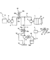
- FIG. 1 is a diagram showing a mixer drum driving device in the present embodiment.
- FIG. 2 is a side view of a mixer truck having a mixer drum mounted on a gantry.
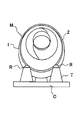
- FIG. 3 is a rear view of the mixer drum mounted on the frame of the mixer vehicle.
- the mixer drum driving device S in this embodiment includes a mixer drum M that is rotatably mounted on a gantry C of the mixer vehicle V, a hydraulic motor 3 that rotationally drives the mixer drum M, and a mixer vehicle.
- a hydraulic pump 4 that is driven by the power of the V engine E to supply pressure oil to the hydraulic motor 3, and an auxiliary that can supply pressure oil to the hydraulic motor 3 independently of the hydraulic pump 4 so as to rotate the mixer drum M with stirring.
- a hydraulic pump 5, a motor 6 with a DC brush that rotationally drives the auxiliary hydraulic pump 5, and a controller 7 that controls the motor 6 with a DC brush are provided.
- the mixer vehicle V includes a leg T attached to the gantry C and a pair of rollers R and R that are rotatably provided on the leg T.
- the pump 4, the auxiliary hydraulic pump 5, the DC brush motor 6, and the controller 7 are mounted on the gantry C.
- the mixer drum M is formed in a bottomed cylindrical shape with an open rear end, and a drum shell 1 whose bottom center shaft portion is connected to the hydraulic motor 3 and a roller provided on the outer periphery of the rear end side of the drum shell 1. And a ring 2.
- the mixer drum M is rotatably attached to the gantry C so as to support the roller ring 2 from below with rollers R and R. Furthermore, the mixer drum M is attached to the gantry C in a forward tilt posture in which the rear end side is lifted upward.
- a plurality of spiral blades are provided on the inner peripheral side of the drum shell 1.
- the mixer drum M When the mixer drum M is rotated forward by this blade, the loaded material such as raw concrete loaded inside is agitated while being moved to the inner side.
- the mixer drum M When the mixer drum M is rotated in the reverse direction, the loaded material is moved to the rear end side and the mixer drum M is moved. Can be discharged from. Furthermore, when putting the raw food into the mixer drum M, the mixer drum M is rotated forward at a higher speed than the stirring rotation.
- the rotation mode of the mixer drum M includes a charging mode used when loading the load, a stirring mode used when stirring the load, and a discharge mode used when discharging the load.
- a charging mode used when loading the load
- a stirring mode used when stirring the load
- a discharge mode used when discharging the load.
- the case where the raw concrete as a load is transported from the concrete plant to the placement site is described as an example.
- the cleaning water is poured into the mixer drum M.
- the present embodiment can be applied even when returning to the concrete plant while charging and cleaning, and in this case, the cleaning water becomes the load.
- the hydraulic motor 3 is set so as to be bi-directionally rotatable, and is connected to the hydraulic pump 4 via a loop-shaped pipe line 8.
- the hydraulic motor 3 is connected to the mixer drum M, and rotates the mixer drum M forward when rotating forward, and reversely rotates the mixer drum M when rotating backward.
- a reduction gear may be interposed between the hydraulic motor 3 and the mixer drum M.
- the hydraulic pump 4 is a one-way discharge type hydraulic pump that is provided in the middle of the pipe line 8 and discharges the pressure oil toward the hydraulic motor 3.
- the hydraulic pump 4 is connected to the engine E of the mixer vehicle V via the PTO 9 and is rotationally driven by the power of the engine E.
- a switching valve 20 is provided in the middle of the pipeline 8.
- the switching valve 20 sends the pressure oil from the hydraulic pump 4 to the hydraulic motor 3 so as to rotate the hydraulic motor 3 forward, and the hydraulic valve 3 to the hydraulic motor 3 so as to reversely rotate the hydraulic oil from the hydraulic pump 4.
- This is a four-port three-position switching valve having three positions: a sending position 20b and a position 20c where the connection between the hydraulic motor 3 and the hydraulic pump 4 is disconnected.
- the hydraulic pump 4 may be set to a bidirectional discharge type.
- the hydraulic pump 4 and the hydraulic motor 3 are connected by a loop pipe line without providing the switching valve 20, and the hydraulic motor 3 is driven to rotate in both forward and reverse directions by switching the discharge direction of the hydraulic pump 4. be able to.
- the auxiliary hydraulic pump 5 is provided in the middle of a pipeline 11 connecting one of the pipelines 8 between the hydraulic motor 3 and the hydraulic pump 4 to the tank 10.
- the other of the pipe lines 8 between the hydraulic motor 3 and the hydraulic pump 4 is connected to the tank 10 by a pipe line 12.
- the DC brush motor 6 is connected to the power source Bat so as to rotate only in one direction.
- the auxiliary hydraulic pump 5 is rotationally driven by an electric motor 6 with a DC brush, sucks oil from the tank 10 and discharges it toward the hydraulic motor 3.
- a switching valve 13 is provided in the middle of the pipeline 11 and the pipeline 12. The switching valve 13 has a position 13a for sending the hydraulic oil discharged from the auxiliary hydraulic pump 5 to the hydraulic motor 3 so as to rotate the hydraulic motor 3 forward, and a pressure discharged from the auxiliary hydraulic pump 5 without going through the hydraulic motor 3.
- a 4-port 2-position switching valve having two positions, a position 13b for returning oil to the tank 10.
- the auxiliary hydraulic pump 5 rotates to suck oil from the tank 10 and discharge pressure oil.
- the switching valve 13 is at the position 13a for supplying pressure oil to the hydraulic motor 3
- the pressure oil discharged from the auxiliary hydraulic pump 5 is supplied to the hydraulic motor 3, and the hydraulic motor 3 rotates forward.
- the mixer drum driving device S in this embodiment has a selection lever 14 that can select the rotation mode of the mixer drum M.
- the mixer drum M rotates in the selected rotation mode.
- the operator operates the selection lever 14 in the direction of the broken line arrow in the drawing to make the charging mode in which the mixer drum M is normally rotated at high speed, the stirring mode in which the mixer drum M is normally rotated at low speed, and the mixer drum M It is possible to select any one of a discharge mode in which the reverse rotation is performed at a high speed.
- the selection lever 14 is connected to a governor (not shown) of the engine E via a link or the like, and can increase the rotation speed of the engine E and rotate the mixer drum M at high speed in the charging mode and the discharging mode.
- the selection lever 14 can drive an actuator such as a solenoid (not shown) that switches the switching valve 20.
- the switching valve 20 In the charging mode and the agitation mode, the switching valve 20 is switched to the position 20a for supplying pressure oil so as to rotate the hydraulic motor 3 forward, and in the discharging mode, the switching valve 20 is pressurized oil so as to reversely rotate the hydraulic motor 3. Is switched to the position 20b.
- the controller 7 is connected to a proximity switch 15 that outputs an ON signal when the selection lever 14 is in the agitation mode, and a switch 17 provided in the middle of the power supply line 16 that connects the power supply Bat and the DC brushed motor 6. ing.
- a proximity switch 15 that outputs an ON signal when the selection lever 14 is in the agitation mode
- a switch 17 provided in the middle of the power supply line 16 that connects the power supply Bat and the DC brushed motor 6. ing.
- an ON signal of the proximity switch 15 is input to the controller 7.
- the controller 7 recognizes an instruction for stirring and rotating the mixer drum M based on the ON signal of the proximity switch 15.
- the controller 7 may be configured to be able to make the above determination and output a signal to the switch 17 to turn the switch 17 on and off.
- the controller 7 When the controller 7 receives an ON signal from the proximity switch 15 and recognizes an instruction to rotate the mixer drum M, the controller 7 turns on the switch 17. Thereby, electric power is supplied from the power source Bat to the DC brushed motor 6 and the auxiliary hydraulic pump 5 is driven. The pressure oil supplied from the auxiliary hydraulic pump 5 drives the hydraulic motor 3 and the mixer drum M rotates with stirring.
- the controller 7 switches the switching valves 13 and 20 in addition to the on operation of the switch 17 described above.
- the controller 7 is connected to an actuator such as a solenoid (not shown) that switches and drives the switching valves 13 and 20.
- an actuator such as a solenoid (not shown) that switches and drives the switching valves 13 and 20.
- the switching valve 13 is switched to the position 13a where the pressure oil discharged from the auxiliary hydraulic pump 5 is sent to the hydraulic motor 3, and the switching valve 20 causes the hydraulic pump 4 to move to the hydraulic motor 3 on the hydraulic circuit.
- the position is switched to the position 20c to be disconnected. That is, the mixer drum M is rotationally driven only by the DC brushed electric motor 6, and the connection between the hydraulic pump 4 and the hydraulic motor 3 is disconnected.
- the controller 7 turns off the switch 17 and stops the DC brushed motor 6. Further, the switching valve 13 is switched to a position 13b where the auxiliary hydraulic pump 5 is disconnected from the hydraulic motor 3 on the hydraulic circuit, that is, a position 13b where the connection between the auxiliary hydraulic pump 5 and the hydraulic motor 3 is disconnected, and the selection lever 14 instructs. Depending on the mode, the switching valve 20 is switched to rotate the hydraulic motor 3 forward or backward.
- auxiliary hydraulic pump 5 By separating the auxiliary hydraulic pump 5 from the hydraulic motor 3, it is possible to prevent the pressure oil of the hydraulic pump 4 from turning to the auxiliary hydraulic pump 5 side and escaping to the tank 10 via the auxiliary hydraulic pump 5, and efficiently mixing the drum drum. M can be charged or rotated.
- control right of the actuator of the switching valve 20 may be given from the controller 7 to the selection lever 14 and the switching of the switching valve 20 may be under the control of the selection lever 14.
- the controller 7 can recognize which mode the selection lever 14 indicates, the controller 7 receives the instruction from the selection lever 14 and the controller 7 controls the actuator of the switching valve 20. You may control.
- the selection lever 14 and the switching valve 20 are connected via a link or the like, and the switching valve 20 is switched by operating the selection lever 14. Good.
- the switch 17 may be connected to the selection lever 14 via a link or the like so as to be interlocked with the movement of the selection lever 14.
- the mixer drum drive device S of the present embodiment rotates the mixer drum M using only the DC brush motor 6 when stirring and rotating. In this way, the maximum torque required for the electric motor can be reduced compared with the case where the mixer drum M is loaded, stirred and discharged only by the electric motor, so an inverter is not required and a DC brush is provided.
- the electric motor 6 and the power source Bat can be reduced in size.
- the DC brushed electric motor 6 that rotates the mixer drum M with stirring, and if this is driven at a constant rotational speed, the amount of pressure oil supplied to the hydraulic motor 3 can be kept constant.
- the mixer drum M can be rotated at a constant rotational speed.
- a variable displacement pump capable of adjusting the discharge flow rate is used as the hydraulic pump so that the discharge flow rate of the hydraulic pump becomes constant even when the engine speed changes.
- a piston pump capable of adjusting the discharge flow rate by adjusting the tilt angle is used, and the tilt angle is adjusted according to the change in the engine rotation speed to discharge a constant flow rate.
- the mixer drum driving device S of the present embodiment can rotate the mixer drum M at a constant rotational speed using the DC brush motor 6 when the mixer drum M is rotated by stirring. It is not necessary to control the discharge flow rate of the hydraulic pump 4 in order to perform stirring and rotation at a constant rotational speed. As a result, it is not necessary to use a variable displacement pump as the hydraulic pump 4, and the hydraulic pump 4 can be reduced in size and weight, and an apparatus for controlling the flow rate becomes unnecessary.
- the motor 6 with DC brush and the power source Bat can be reduced in weight, the inverter can be eliminated, the hydraulic pump 4 can be reduced in weight, and the flow control of the hydraulic pump 4 can be eliminated. Can be secured sufficiently. Furthermore, since the mixer vehicle V becomes light, the amount of raw concrete can be increased by the amount lightened. Therefore, the mixer drum M can be driven by the electric motor without causing a decrease in the transport efficiency due to a decrease in the transport amount of the raw concrete.
- the transport efficiency is not lowered, the amount of fuel consumed by the mixer vehicle V can be reduced.
- the rotation speed of the auxiliary hydraulic pump 5 may be constant in one direction, and the rotation speed of the DC brushed motor 6 is also constant rotation. Good.
- the DC brushed motor 6 and the power source Bat can be reduced in weight and size, the inverter can be eliminated, the hydraulic pump 4 can be reduced in size and the flow control of the hydraulic pump 4 can be eliminated, and no inverter is required.
- the manufacturing cost can be reduced.
- the drive system of the mixer drum M is two systems of the engine E and the DC brushed motor 6, even if any trouble occurs in any one system and the mixer drum M cannot be driven, the other system Thus, the mixer drum M can be driven to rotate.
- a clutch may be provided between the PTO 9 and the hydraulic pump 4, and the connection between the engine E and the hydraulic pump 4 may be disconnected during the stirring rotation of the mixer drum M.
- the engine E This power can be used only for the traveling of the mixer vehicle V, so that the fuel consumption can be further reduced.
- the mixer drum M when the selection lever 14 is in the position for instructing the stirring mode, the mixer drum M is in the stirring rotation by the ON signal from the proximity switch 15 that outputs the ON signal when the selection lever 14 approaches.
- the controller 7 may recognize that the stirring mode is selected using another sensor, and an operation button or a selection switch may be used instead of the selection lever 14. It is.
- a weight sensor that detects the weight of the mixer drum M is provided on the leg T that supports the mixer drum M, and in addition to the instruction of stirring rotation of the mixer drum M, the weight detected by the weight sensor is equal to or greater than a predetermined weight.
- the mixer drum M may be rotationally driven by driving the electric motor 6 with a DC brush.
- the mixer drum M loaded with a load is heavier when the loaded material such as raw concrete and washing water is loaded on the mixer drum M and when it is not loaded. Therefore, by setting the predetermined weight to a weight that exceeds the empty mixer drum M, it is possible to determine whether or not a load such as raw concrete is loaded in the mixer drum M.
- the weight detected by the weight sensor does not exceed the predetermined weight, so that power is wasted by driving the DC brushed motor 6 when the engine is stopped. Can be prevented.
- a load such as raw concrete or washing water is loaded in the mixer drum M is determined in accordance with the flow direction of the pressure oil in the pipe 8 when the hydraulic motor 3 is rotated forward. It can also be performed by detecting the pressure upstream of the motor 3. In the state in which the load is loaded on the mixer drum M and the state in which the load is not loaded, the load loaded state requires a larger torque when the mixer drum M is driven to rotate. The pressure also increases. Therefore, by setting the predetermined pressure as the pressure oil pressure when the hydraulic motor 3 is driven in a state where the load is loaded on the mixer drum M, it is determined whether or not the load is loaded in the mixer drum M. Judgment can be made.
- a pressure switch that is turned on at the predetermined pressure and outputs a turn-on signal to the controller 7 is provided, and when the turn-on signal is input, the controller determines that the load is being loaded in the mixer drum M. 7 may be determined.
Landscapes
- Engineering & Computer Science (AREA)
- Mechanical Engineering (AREA)
- General Engineering & Computer Science (AREA)
- Structural Engineering (AREA)
- Preparation Of Clay, And Manufacture Of Mixtures Containing Clay Or Cement (AREA)
Abstract
Priority Applications (6)
| Application Number | Priority Date | Filing Date | Title |
|---|---|---|---|
| US14/006,845 US9481106B2 (en) | 2011-03-24 | 2012-03-15 | Mixer drum driving device |
| NZ616170A NZ616170B2 (en) | 2011-03-24 | 2012-03-15 | Mixer drum driving device |
| EP12761055.8A EP2689962A4 (fr) | 2011-03-24 | 2012-03-15 | Dispositif d'entraînement de benne de malaxage |
| AU2012232247A AU2012232247A1 (en) | 2011-03-24 | 2012-03-15 | Mixer drum driving device |
| CN201280014548.0A CN103442944B (zh) | 2011-03-24 | 2012-03-15 | 搅拌筒驱动装置 |
| AU2016201320A AU2016201320B2 (en) | 2011-03-24 | 2016-03-01 | Mixer drum driving device |
Applications Claiming Priority (2)
| Application Number | Priority Date | Filing Date | Title |
|---|---|---|---|
| JP2011-065506 | 2011-03-24 | ||
| JP2011065506A JP5833829B2 (ja) | 2011-03-24 | 2011-03-24 | ミキサドラム駆動装置 |
Publications (1)
| Publication Number | Publication Date |
|---|---|
| WO2012128174A1 true WO2012128174A1 (fr) | 2012-09-27 |
Family
ID=46879324
Family Applications (1)
| Application Number | Title | Priority Date | Filing Date |
|---|---|---|---|
| PCT/JP2012/056684 Ceased WO2012128174A1 (fr) | 2011-03-24 | 2012-03-15 | Dispositif d'entraînement de benne de malaxage |
Country Status (6)
| Country | Link |
|---|---|
| US (1) | US9481106B2 (fr) |
| EP (1) | EP2689962A4 (fr) |
| JP (1) | JP5833829B2 (fr) |
| CN (1) | CN103442944B (fr) |
| AU (2) | AU2012232247A1 (fr) |
| WO (1) | WO2012128174A1 (fr) |
Cited By (2)
| Publication number | Priority date | Publication date | Assignee | Title |
|---|---|---|---|---|
| JP2014196094A (ja) * | 2013-03-29 | 2014-10-16 | カヤバ工業株式会社 | ミキサ車 |
| CN105500529A (zh) * | 2014-09-25 | 2016-04-20 | 中联重科股份有限公司 | 搅拌筒的速度调节的方法、装置及混凝土搅拌运输车 |
Families Citing this family (8)
| Publication number | Priority date | Publication date | Assignee | Title |
|---|---|---|---|---|
| DE102010047314B4 (de) * | 2010-10-01 | 2014-10-30 | Shanghai Electric Hydraulics & Pneumatics Co., Ltd. | Hybridantrieb für Fahrmischertrommel |
| JP5798771B2 (ja) * | 2011-03-24 | 2015-10-21 | カヤバ工業株式会社 | ミキサドラム駆動装置 |
| JP5952599B2 (ja) * | 2011-03-24 | 2016-07-13 | Kyb株式会社 | ミキサドラム駆動装置 |
| JP5825719B2 (ja) * | 2012-03-22 | 2015-12-02 | Kyb株式会社 | ミキサドラム駆動装置 |
| IT201800006841A1 (it) * | 2018-07-02 | 2020-01-02 | Apparato di azionamento di una macchina operatrice mobile e macchina operatrice mobile comprendente tale apparato di azionamento | |
| IT201800006838A1 (it) * | 2018-07-02 | 2020-01-02 | Macchina operatrice mobile e metodo di funzionamento di tale macchina operatrice mobile | |
| US12472661B2 (en) * | 2020-01-31 | 2025-11-18 | Oshkosh Corporation | Mixer drum drive with additional pump |
| CN112983906B (zh) * | 2021-04-21 | 2021-08-06 | 探擎(上海)技术服务有限公司 | 一种节能搅拌装置及节能方法 |
Citations (4)
| Publication number | Priority date | Publication date | Assignee | Title |
|---|---|---|---|---|
| JPS6039001B2 (ja) * | 1978-06-14 | 1985-09-04 | 株式会社デンソー | 電気的駆動装置 |
| JP2003294008A (ja) * | 2002-04-04 | 2003-10-15 | Kayaba Ind Co Ltd | 油圧制御装置 |
| JP2003301802A (ja) * | 2002-02-06 | 2003-10-24 | Kayaba Ind Co Ltd | ミキサ車 |
| JP2007278430A (ja) | 2006-04-10 | 2007-10-25 | Shin Meiwa Ind Co Ltd | ミキサ車のミキサドラム駆動装置 |
Family Cites Families (9)
| Publication number | Priority date | Publication date | Assignee | Title |
|---|---|---|---|---|
| US3053044A (en) | 1958-11-07 | 1962-09-11 | Ready Mixed Concrete Ltd | Hydraulic transmission systems |
| US5269604A (en) * | 1993-04-06 | 1993-12-14 | Ewers R Otto | Slurry hauling vehicle |
| US7792618B2 (en) * | 2001-12-21 | 2010-09-07 | Oshkosh Corporation | Control system and method for a concrete vehicle |
| US7552847B2 (en) * | 2003-05-09 | 2009-06-30 | Intellipack | Dispenser mixing module and method of assembling and using same |
| US20070263478A1 (en) * | 2006-05-15 | 2007-11-15 | Burch Leon A | Hydraulic power system |
| CN201279835Y (zh) * | 2008-10-09 | 2009-07-29 | 上海华丰工业控制技术工程有限公司 | 搅拌筒恒速控制系统、恒速搅拌的运输车及其电控发动机 |
| CN102205559B (zh) * | 2010-11-09 | 2013-01-23 | 江苏卡威专用汽车制造有限公司 | 混凝土搅拌运输车搅拌筒恒转速控制装置 |
| CN102275223B (zh) * | 2011-09-20 | 2013-04-10 | 四川大学 | 一种新型的混凝土搅拌运输车搅拌筒转动驱动系统 |
| JP6039001B2 (ja) * | 2015-05-12 | 2016-12-07 | 株式会社藤商事 | 遊技機 |
-
2011
- 2011-03-24 JP JP2011065506A patent/JP5833829B2/ja active Active
-
2012
- 2012-03-15 EP EP12761055.8A patent/EP2689962A4/fr not_active Withdrawn
- 2012-03-15 AU AU2012232247A patent/AU2012232247A1/en not_active Abandoned
- 2012-03-15 US US14/006,845 patent/US9481106B2/en not_active Expired - Fee Related
- 2012-03-15 CN CN201280014548.0A patent/CN103442944B/zh not_active Expired - Fee Related
- 2012-03-15 WO PCT/JP2012/056684 patent/WO2012128174A1/fr not_active Ceased
-
2016
- 2016-03-01 AU AU2016201320A patent/AU2016201320B2/en not_active Ceased
Patent Citations (4)
| Publication number | Priority date | Publication date | Assignee | Title |
|---|---|---|---|---|
| JPS6039001B2 (ja) * | 1978-06-14 | 1985-09-04 | 株式会社デンソー | 電気的駆動装置 |
| JP2003301802A (ja) * | 2002-02-06 | 2003-10-24 | Kayaba Ind Co Ltd | ミキサ車 |
| JP2003294008A (ja) * | 2002-04-04 | 2003-10-15 | Kayaba Ind Co Ltd | 油圧制御装置 |
| JP2007278430A (ja) | 2006-04-10 | 2007-10-25 | Shin Meiwa Ind Co Ltd | ミキサ車のミキサドラム駆動装置 |
Non-Patent Citations (1)
| Title |
|---|
| See also references of EP2689962A4 |
Cited By (3)
| Publication number | Priority date | Publication date | Assignee | Title |
|---|---|---|---|---|
| JP2014196094A (ja) * | 2013-03-29 | 2014-10-16 | カヤバ工業株式会社 | ミキサ車 |
| CN105500529A (zh) * | 2014-09-25 | 2016-04-20 | 中联重科股份有限公司 | 搅拌筒的速度调节的方法、装置及混凝土搅拌运输车 |
| CN105500529B (zh) * | 2014-09-25 | 2018-06-12 | 中联重科股份有限公司 | 搅拌筒的速度调节的方法、装置及混凝土搅拌运输车 |
Also Published As
| Publication number | Publication date |
|---|---|
| US9481106B2 (en) | 2016-11-01 |
| JP2012201144A (ja) | 2012-10-22 |
| US20140010036A1 (en) | 2014-01-09 |
| AU2016201320A1 (en) | 2016-03-17 |
| EP2689962A4 (fr) | 2016-01-13 |
| AU2012232247A1 (en) | 2013-10-24 |
| EP2689962A1 (fr) | 2014-01-29 |
| AU2016201320B2 (en) | 2017-09-07 |
| JP5833829B2 (ja) | 2015-12-16 |
| CN103442944A (zh) | 2013-12-11 |
| NZ616170A (en) | 2014-12-24 |
| CN103442944B (zh) | 2016-08-17 |
Similar Documents
| Publication | Publication Date | Title |
|---|---|---|
| WO2012128174A1 (fr) | Dispositif d'entraînement de benne de malaxage | |
| JP5952599B2 (ja) | ミキサドラム駆動装置 | |
| CN104203644B (zh) | 搅拌筒驱动装置 | |
| JP5649177B2 (ja) | ミキサドラム駆動装置 | |
| JP5923415B2 (ja) | ミキサドラムの駆動装置 | |
| NZ616170B2 (en) | Mixer drum driving device | |
| NZ616173B2 (en) | Mixer drum driving device | |
| NZ605815B (en) | Mixer drum driving device |
Legal Events
| Date | Code | Title | Description |
|---|---|---|---|
| 121 | Ep: the epo has been informed by wipo that ep was designated in this application |
Ref document number: 12761055 Country of ref document: EP Kind code of ref document: A1 |
|
| WWE | Wipo information: entry into national phase |
Ref document number: 14006845 Country of ref document: US |
|
| NENP | Non-entry into the national phase |
Ref country code: DE |
|
| ENP | Entry into the national phase |
Ref document number: 2012232247 Country of ref document: AU Date of ref document: 20120315 Kind code of ref document: A |
|
| WWE | Wipo information: entry into national phase |
Ref document number: 2012761055 Country of ref document: EP |