WO2012128251A1 - ポリマー含有現像液 - Google Patents
ポリマー含有現像液 Download PDFInfo
- Publication number
- WO2012128251A1 WO2012128251A1 PCT/JP2012/057019 JP2012057019W WO2012128251A1 WO 2012128251 A1 WO2012128251 A1 WO 2012128251A1 JP 2012057019 W JP2012057019 W JP 2012057019W WO 2012128251 A1 WO2012128251 A1 WO 2012128251A1
- Authority
- WO
- WIPO (PCT)
- Prior art keywords
- resist
- developer
- polymer
- forming
- resist film
- Prior art date
- Legal status (The legal status is an assumption and is not a legal conclusion. Google has not performed a legal analysis and makes no representation as to the accuracy of the status listed.)
- Ceased
Links
Classifications
-
- G—PHYSICS
- G03—PHOTOGRAPHY; CINEMATOGRAPHY; ANALOGOUS TECHNIQUES USING WAVES OTHER THAN OPTICAL WAVES; ELECTROGRAPHY; HOLOGRAPHY
- G03F—PHOTOMECHANICAL PRODUCTION OF TEXTURED OR PATTERNED SURFACES, e.g. FOR PRINTING, FOR PROCESSING OF SEMICONDUCTOR DEVICES; MATERIALS THEREFOR; ORIGINALS THEREFOR; APPARATUS SPECIALLY ADAPTED THEREFOR
- G03F7/00—Photomechanical, e.g. photolithographic, production of textured or patterned surfaces, e.g. printing surfaces; Materials therefor, e.g. comprising photoresists; Apparatus specially adapted therefor
- G03F7/26—Processing photosensitive materials; Apparatus therefor
- G03F7/30—Imagewise removal using liquid means
- G03F7/32—Liquid compositions therefor, e.g. developers
- G03F7/325—Non-aqueous compositions
-
- G—PHYSICS
- G03—PHOTOGRAPHY; CINEMATOGRAPHY; ANALOGOUS TECHNIQUES USING WAVES OTHER THAN OPTICAL WAVES; ELECTROGRAPHY; HOLOGRAPHY
- G03F—PHOTOMECHANICAL PRODUCTION OF TEXTURED OR PATTERNED SURFACES, e.g. FOR PRINTING, FOR PROCESSING OF SEMICONDUCTOR DEVICES; MATERIALS THEREFOR; ORIGINALS THEREFOR; APPARATUS SPECIALLY ADAPTED THEREFOR
- G03F7/00—Photomechanical, e.g. photolithographic, production of textured or patterned surfaces, e.g. printing surfaces; Materials therefor, e.g. comprising photoresists; Apparatus specially adapted therefor
- G03F7/004—Photosensitive materials
- G03F7/09—Photosensitive materials characterised by structural details, e.g. supports, auxiliary layers
- G03F7/094—Multilayer resist systems, e.g. planarising layers
-
- G—PHYSICS
- G03—PHOTOGRAPHY; CINEMATOGRAPHY; ANALOGOUS TECHNIQUES USING WAVES OTHER THAN OPTICAL WAVES; ELECTROGRAPHY; HOLOGRAPHY
- G03F—PHOTOMECHANICAL PRODUCTION OF TEXTURED OR PATTERNED SURFACES, e.g. FOR PRINTING, FOR PROCESSING OF SEMICONDUCTOR DEVICES; MATERIALS THEREFOR; ORIGINALS THEREFOR; APPARATUS SPECIALLY ADAPTED THEREFOR
- G03F7/00—Photomechanical, e.g. photolithographic, production of textured or patterned surfaces, e.g. printing surfaces; Materials therefor, e.g. comprising photoresists; Apparatus specially adapted therefor
- G03F7/004—Photosensitive materials
- G03F7/09—Photosensitive materials characterised by structural details, e.g. supports, auxiliary layers
- G03F7/11—Photosensitive materials characterised by structural details, e.g. supports, auxiliary layers having cover layers or intermediate layers, e.g. subbing layers
-
- G—PHYSICS
- G03—PHOTOGRAPHY; CINEMATOGRAPHY; ANALOGOUS TECHNIQUES USING WAVES OTHER THAN OPTICAL WAVES; ELECTROGRAPHY; HOLOGRAPHY
- G03F—PHOTOMECHANICAL PRODUCTION OF TEXTURED OR PATTERNED SURFACES, e.g. FOR PRINTING, FOR PROCESSING OF SEMICONDUCTOR DEVICES; MATERIALS THEREFOR; ORIGINALS THEREFOR; APPARATUS SPECIALLY ADAPTED THEREFOR
- G03F7/00—Photomechanical, e.g. photolithographic, production of textured or patterned surfaces, e.g. printing surfaces; Materials therefor, e.g. comprising photoresists; Apparatus specially adapted therefor
- G03F7/26—Processing photosensitive materials; Apparatus therefor
- G03F7/40—Treatment after imagewise removal, e.g. baking
-
- H—ELECTRICITY
- H10—SEMICONDUCTOR DEVICES; ELECTRIC SOLID-STATE DEVICES NOT OTHERWISE PROVIDED FOR
- H10P—GENERIC PROCESSES OR APPARATUS FOR THE MANUFACTURE OR TREATMENT OF DEVICES COVERED BY CLASS H10
- H10P50/00—Etching of wafers, substrates or parts of devices
-
- H—ELECTRICITY
- H10—SEMICONDUCTOR DEVICES; ELECTRIC SOLID-STATE DEVICES NOT OTHERWISE PROVIDED FOR
- H10P—GENERIC PROCESSES OR APPARATUS FOR THE MANUFACTURE OR TREATMENT OF DEVICES COVERED BY CLASS H10
- H10P76/00—Manufacture or treatment of masks on semiconductor bodies, e.g. by lithography or photolithography
- H10P76/20—Manufacture or treatment of masks on semiconductor bodies, e.g. by lithography or photolithography of masks comprising organic materials
- H10P76/204—Manufacture or treatment of masks on semiconductor bodies, e.g. by lithography or photolithography of masks comprising organic materials of organic photoresist masks
- H10P76/2041—Photolithographic processes
- H10P76/2042—Photolithographic processes using lasers
-
- H—ELECTRICITY
- H10—SEMICONDUCTOR DEVICES; ELECTRIC SOLID-STATE DEVICES NOT OTHERWISE PROVIDED FOR
- H10P—GENERIC PROCESSES OR APPARATUS FOR THE MANUFACTURE OR TREATMENT OF DEVICES COVERED BY CLASS H10
- H10P76/00—Manufacture or treatment of masks on semiconductor bodies, e.g. by lithography or photolithography
- H10P76/40—Manufacture or treatment of masks on semiconductor bodies, e.g. by lithography or photolithography of masks comprising inorganic materials
- H10P76/408—Manufacture or treatment of masks on semiconductor bodies, e.g. by lithography or photolithography of masks comprising inorganic materials characterised by their sizes, orientations, dispositions, behaviours or shapes
- H10P76/4085—Manufacture or treatment of masks on semiconductor bodies, e.g. by lithography or photolithography of masks comprising inorganic materials characterised by their sizes, orientations, dispositions, behaviours or shapes characterised by the processes involved to create the masks
Definitions
- the present invention relates to a developer used in a lithography process.
- fine processing by lithography using a photoresist composition has been performed in the manufacture of semiconductor devices.
- the fine processing was obtained by forming a thin film of a photoresist composition on a silicon wafer, irradiating with an actinic ray such as ultraviolet rays through a mask pattern on which a semiconductor device pattern was drawn, and developing it.
- This is a processing method of etching a silicon wafer using a resist pattern as a protective film.
- the cause of the pattern collapse is thought to be due to the surface tension when the developer or the rinsing liquid dries and the force acting between the patterns due to the flow of the liquid, that is, the Laplace force. Further, it is considered that the Laplace force is generated and the pattern collapses when the developer or the rinsing solution is blown outward using centrifugal force.
- a step of forming a resist film on a substrate, a step of selectively irradiating the resist film with energy rays to form a latent image on the resist film, and the latent image In order to form a resist pattern from the formed resist film, a step of supplying a developing solution (alkaline developing solution) onto the resist film, and to replace the developing solution on the substrate with a rinsing solution, the substrate Supplying the rinsing liquid onto the substrate, and replacing the rinsing liquid on the substrate with a coating film material comprising a solvent different from the resist film and a solute different from the resist film; Supplying a coating material; volatilizing a solvent in the coating film material to form a coating film covering the resist film on the substrate; and at least one of the upper surfaces of the resist pattern
- An object of the present invention is to provide a developer that does not cause pattern collapse when a fine pattern is formed, and a pattern forming method using the developer.
- a first aspect of the present invention is a developer used in a lithography process, which includes a polymer for forming a dry etching mask and an organic solvent
- the developer according to the first aspect wherein the polymer is a curable resin different from the curable resin forming the resist film
- the developer is the developer according to the first aspect or the second aspect used after exposure of the resist film
- the developer according to any one of the first to third aspects wherein the organic solvent of the developer is butyl acetate or a mixed solvent of butyl acetate and alcohol
- the developer according to any one of the first to third aspects wherein the organic solvent of the developer is 2-pentanone or a mixed solvent of 2-pentanone and alcohol
- the developer according to any one of the first aspect to the fifth aspect in which the polymer is a novolak resin or a polyorganosiloxane
- the developer according to any one of the first aspect to the fifth aspect in which the polymer is a novolak resin or a polyorganosilox
- the resist film is formed in the step (A) by forming a resist underlayer film on the semiconductor substrate and forming a resist film thereon.
- the resist film is formed in the step (A) by forming a resist underlayer film on the semiconductor substrate and forming a resist film thereon.
- Production method As a tenth aspect, in the formation of the resist film in the step (A), an organic underlayer film is formed on a semiconductor substrate, a hard mask containing silicon atoms is formed thereon, and a resist film is formed thereon.
- the formation of the polymer layer includes applying heat.
- the manufacturing method according to any one of the eighth aspect to the tenth aspect, and the twelfth aspect In the step (C), the method according to any one of the eighth to eleventh aspects, wherein the resist / polymer dry etching rate ratio is 1.0 or more.
- a resist containing a polymer is brought into contact with the resist film, whereby a pattern is formed on the resist film and the pattern is formed between the patterns. Since the polymer is filled, resist collapse can be prevented during development and cleaning.
- the polymer is a kind of curable resin different from the curable resin forming the resist film, only the resist film can be selectively removed by dry etching. This makes it possible to form a new fine pattern with the polymer.
- the exposed resist surface is developed with a developing solution, washed with a rinsing solution, the rinsing solution is replaced with a coating solution containing a polymer component, and the resist pattern is coated with the polymer component. Thereafter, the resist is removed by dry etching to form a reverse pattern with the replaced polymer component.
- the resist surface after mask exposure is contacted with a developer containing a polymer for forming a dry etching mask, and the exposed portion of the resist is insoluble in an organic solvent and the unexposed portion is dissolved in an organic solvent-containing developer.
- the resist pattern is filled with a polymer between the resist patterns to prevent collapse of the resist pattern. Thereafter, the surface filled with the resist pattern is dry-etched to remove the resist pattern, and the filled polymer becomes a new resist pattern. This can also be called a reverse process.
- the resist layer and the polymer to be filled are preferably a combination in which the dry etching rate varies depending on the gas type used for dry etching.
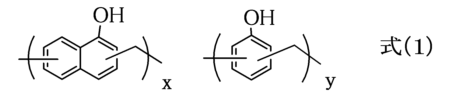
- the polymer layer to be filled The polymer is preferably a resin having a high carbon content such as a novolak resin (phenol novolak resin, naphthol novolak resin, or a combination thereof), or a polyorganosiloxane material.
- the present invention is a polymer capable of forming a new pattern in a subsequent process between resist patterns developed and removed while developing an unexposed portion by coating the exposed resist with a developer containing a polymer. Since filling is performed, the initial resist pattern can be filled without collapsing, and a fine pattern that does not collapse can be formed by a reverse pattern (reverse pattern) in a subsequent dry etching process.
- the present invention is a resist developer used in a lithography process containing a polymer for forming a dry etching mask and an organic solvent.
- the developer is a solution in which the polymer for forming a dry etching mask is dissolved in an organic solvent, and the solid content is 0.5 to 20.0% by mass, or 1.0 to 10.0% by mass.
- the solid content is the remaining ratio after removing the organic solvent from the developer.
- the proportion of the dry etching mask forming polymer in the solid content is 50 to 100% by mass, or 80 to 100% by mass.
- the concentration of the polymer for forming a dry etching mask in the developer is 0.5 to 20.0% by mass.
- the portion removed by the developer after exposure through the mask is an unexposed portion.
- the polymer for forming the dry etching mask is a curable resin different from the curable resin for forming the resist film.
- a new pattern is formed by the dry etching mask forming polymer filled by selectively removing the resist by dry etching by selecting the gas type.
- butyl acetate is preferred as the solvent not containing a hydroxy group, and a mixed solvent of alcohol and butyl acetate can be exemplified.
- An example is an organic solvent in which 4-methyl-2-pentanol and butyl acetate are mixed at a mass ratio of 1:99 to 20:80.
- a mixed solvent of propylene glycol monomethyl ether and butyl acetate can be mentioned.
- examples thereof include an organic solvent in which propylene glycol monomethyl ether and butyl acetate are mixed at a mass ratio of 1:99 to 20:80.
- the polymer for forming a dry etching mask contained in the developer examples include a curable resin different from the curable resin for forming a resist film.
- the polymer of the polymer layer to be filled is a resin having a high carbon content such as a novolak resin (phenol novolak resin, naphthol novolak resin, or a combination thereof), or a polyorganosiloxane material. Is preferably used.
- novolac resins are as follows.
- a novolak resin containing the above unit structure or a combination of the above unit structures can be used.
- the weight average molecular weight of the polymer having the unit structure of the formula (1) can be in the range of 1000 to 30000, or 2000 to 10,000.
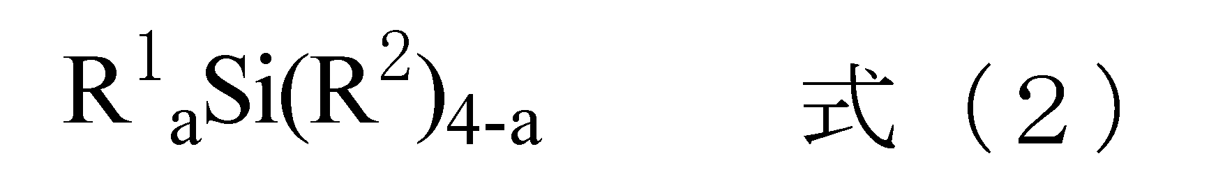
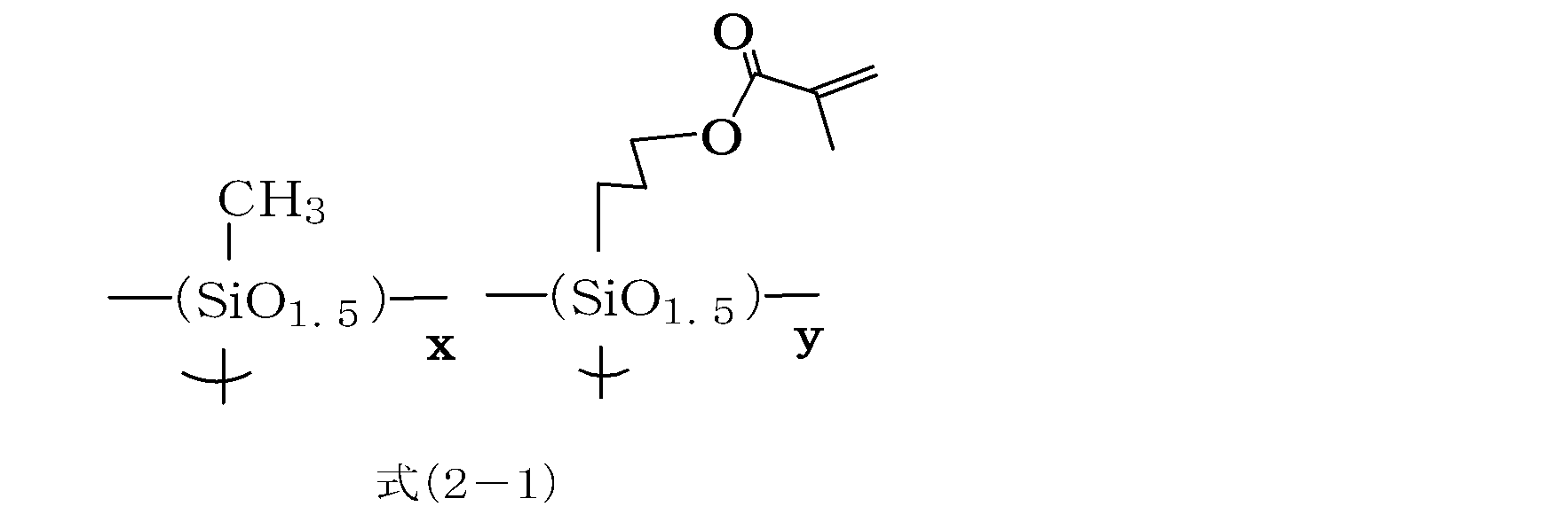
- polysiloxane resin polysiloxane obtained by hydrolyzing and condensing at least one hydrolyzable silane selected from the following formula (2) can be used.
- R 1 is an alkyl group, aryl group, aralkyl group, halogenated alkyl group, halogenated aryl group, halogenated aralkyl group, alkenyl group, or epoxy group, acryloyl group, methacryloyl group, mercapto group, alkoxyaryl group, An acyloxyaryl group, an organic group having a cyano group, or a combination thereof, and bonded to a silicon atom by a Si—C bond, and R 2 represents an alkoxy group, an acyloxy group, or a halogen group.
- A represents an integer of 0-3.
- the weight average molecular weight of the polysiloxane obtained by hydrolyzing and condensing at least one hydrolyzable silane selected from the formula (2) is in the range of 500 to 30,000 or 800 to 10,000.
- hydrolysis 0.5 to 100 mol, preferably 1 to 10 mol of water is used per mol of the hydrolyzable group for the hydrolysis of the alkoxysilyl group, the acyloxysilyl group, or the halogenated silyl group. Further, 0.001 to 10 mol, preferably 0.001 to 1 mol of hydrolysis catalyst can be used per mol of hydrolyzable group.
- the reaction temperature for the hydrolysis and condensation is usually 20 to 80 ° C.
- Hydrolysis may be performed completely or partially. That is, a hydrolyzate or a monomer may remain in the hydrolysis condensate.
- a catalyst can be used in the hydrolysis and condensation.
- hydrolysis catalyst examples include metal chelate compounds, organic acids, inorganic acids, organic bases, and inorganic bases.
- Organic acids as hydrolysis catalysts are, for example, acetic acid, propionic acid, butanoic acid, pentanoic acid, hexanoic acid, heptanoic acid, octanoic acid, nonanoic acid, decanoic acid, oxalic acid, maleic acid, methylmalonic acid, adipic acid, sebacin Acid, gallic acid, butyric acid, meritic acid, arachidonic acid, mikimic acid, 2-ethylhexanoic acid, oleic acid, stearic acid, linoleic acid, linolenic acid, salicylic acid, benzoic acid, p-aminobenzoic acid, p-toluenesulfonic acid Benzenesulfonic acid, monochloroacetic acid, dichloroacetic acid, trichloroacetic acid, trifluoroacetic acid, formic acid, malonic acid, sulfonic acid
- Examples of the inorganic acid as the hydrolysis catalyst include hydrochloric acid, nitric acid, sulfuric acid, hydrofluoric acid, phosphoric acid and the like.
- Organic bases as hydrolysis catalysts include, for example, pyridine, pyrrole, piperazine, pyrrolidine, piperidine, picoline, trimethylamine, triethylamine, monoethanolamine, diethanolamine, dimethylmonoethanolamine, monomethyldiethanolamine, triethanolamine, diazabicyclooctane, diazine.
- Examples include zabicyclononane, diazabicycloundecene, and tetramethylammonium hydroxide.
- the inorganic base include ammonia, sodium hydroxide, potassium hydroxide, barium hydroxide, calcium hydroxide and the like. Of these catalysts, metal chelate compounds, organic acids, and inorganic acids are preferred, and these may be used alone or in combination of two or more.
- organic solvent used for the hydrolysis examples include n-pentane, i-pentane, n-hexane, i-hexane, n-heptane, i-heptane, 2,2,4-trimethylpentane, n-octane, i- Aliphatic hydrocarbon solvents such as octane, cyclohexane and methylcyclohexane; benzene, toluene, xylene, ethylbenzene, trimethylbenzene, methylethylbenzene, n-propyl benzene, i-propyl benzene, diethylbenzene, i-butylbenzene, triethylbenzene, di Aromatic hydrocarbon solvents such as i-propyl benzene, n-amyl naphthalene and trimethylbenzene; methanol, ethanol, n-propy
- Ethers such as 4-methyl-2-pentanol, dipropylene glycol monomethyl ether, dipropylene glycol monoethyl ether, dipropylene glycol monopropyl ether, dipropylene glycol monobutyl ether, tripropylene glycol monomethyl ether, tetrahydrofuran and 2-methyltetrahydrofuran Solvents: diethyl carbonate, methyl acetate, ethyl acetate, ⁇ -butyrolactone, ⁇ -valerolactone, n-propyl acetate, i-propyl acetate, n-butyl acetate, i-butyl acetate, sec-butyl acetate, n-pentyl acetate Sec-pentyl acetate, 3-methoxybutyl acetate, methyl pentyl acetate, 2-ethylbutyl acetate, 2-ethylhexyl acetate,
- the present invention includes a step (A) of coating a semiconductor substrate with a resist to form a resist layer, and exposing, the developer according to any one of the first to seventh aspects being brought into contact with the surface of the resist layer,
- This is a method for manufacturing a semiconductor device, which includes a step (B) of forming a polymer layer between resist patterns and a step (C) of removing the resist layer by dry etching to form a reverse pattern of the polymer.
- Examples of the resist material used in step (A) include a resist having a resin component such as polymethacrylate. After the resist solution is applied, baking is performed at a baking temperature of 70.0 to 150.0 ° C. and a baking time of 0.5 to 5 minutes, and the resist film thickness is obtained in the range of 10 to 1000 nm.
- the resist solution, the developer, and the coating materials shown below can be coated by spin coating, dipping, spraying, or the like, but the spin coating method is particularly preferable.
- the resist is exposed through a predetermined mask.
- a KrF excimer laser (wavelength 248 nm), an ArF excimer laser (wavelength 193 nm), EUV light (wavelength 13.5 nm), an electron beam, or the like can be used.
- post-exposure heating (PEB: Post-Exposure-Bake) may be performed as necessary.
- the post-exposure heating is appropriately selected from a heating temperature of 70 ° C. to 150 ° C. and a heating time of 0.3 to 10 minutes.
- a resist underlayer film is formed on the semiconductor substrate, and the resist can be formed thereon.
- an organic underlayer film can be formed on a semiconductor substrate, a silicon hard mask can be formed thereon, and a resist can be formed thereon.
- the resist underlayer film used in the above step (A) is for preventing irregular reflection during exposure of the upper layer resist, and is used for the purpose of improving the adhesion with the resist.
- an acrylic resin or a novolac type Resin can be used.
- As the resist underlayer film a film having a film thickness of 1 to 1000 nm can be formed on a semiconductor substrate.
- the organic underlayer film used in the step (A) is a hard mask using an organic resin, and a material having a high carbon content and a low hydrogen content is used.
- a material having a high carbon content and a low hydrogen content is used.
- polyvinyl naphthalene resin, carbazole novolak resin, phenol novolak resin, naphthol novolak resin, and the like can be given. These can form a film with a film thickness of 5 to 1000 nm on a semiconductor substrate.
- the silicon hard mask used in the step (A) is obtained by hydrolyzing at least one hydrolyzable silane selected from the following formula (2) as the polysiloxane resin.
- Polysiloxane can be used.
- polysiloxane obtained by hydrolyzing tetraethoxysilane, methyltrimethoxysilane, and phenyltriethoxysilane can be exemplified. These can form a film with a film thickness of 5 to 200 nm on the organic underlayer film.
- the polymer for forming the dry etching mask forming polymer layer can be formed by heating.
- the heating is performed at a firing temperature of 50 to 180 ° C. for 0.5 to 5 minutes.
- step (C) dry etching is performed using tetrafluoromethane, perfluorocyclobutane (C 4 F 8 ), perfluoropropane (C 3 F 8 ), trifluoromethane, carbon monoxide, argon, oxygen, nitrogen, sulfur hexafluoride. , Gas such as difluoromethane, nitrogen trifluoride and chlorine trifluoride.
- the weight average molecular weight was 26000) 3 g was dissolved in 3.88 g of 4-methyl-2-pentanol and 93.12 g of butyl acetate to obtain a developer containing a polymer for forming a dry etching mask. (Replacement of unexposed resist and patterning by dry etching)
- Example 1 A resist underlayer film (commercial product, resin component is polymethacrylate) is formed on a silicon substrate with a film thickness of 80 nm using a spinner, and an ArF resist solution (commercial product, resin component is polymethacrylate) is formed on the film. It applied using the spinner.
- a resist film having a thickness of 100 nm was formed by heating at 100 ° C. for 60 seconds on a hot plate. Exposure is performed under predetermined conditions using an ArF excimer laser exposure apparatus (manufactured by NIKON, S307E). The target line width was set to 65 nm line and space, and after exposure, heating (PEB) was performed at 105 ° C. for 60 seconds, and then cooled to room temperature on a cooling plate.
- PEB ArF excimer laser exposure apparatus
- the developer obtained in Synthesis Example 1 is deposited on the resist film, allowed to stand for 60 seconds, spun at 1500 rpm for 60 seconds to spin dry the solvent, and then the developer of Synthesis Example 1 is deposited for 5 seconds.
- the pattern formation film and the resist non-exposed portion were replaced by allowing to stand and spinning at 1500 rpm for 60 seconds. Presence / absence of substitution of the resist unexposed portion was determined by cross-sectional SEM observation.
- Example 2 The same procedure as in Example 1 was performed except that the developer of Synthesis Example 2 was used instead of the developer of Synthesis Example 1.
- Example 1 Comparative Example 1 In Example 1, the same procedure as in Example 1 was performed, except that a developer composed only of an organic solvent was spin-coated, and then the developer of Example 1 was used.
- the evaluation of the embedding property of the polymer with the developer containing the polymer for forming the dry etching mask is defined as “good” when the pattern formation is good as observed by the cross-sectional SEM, and the pattern formation is poor or the pattern formation is not performed
- the case was “None”.
- the case where there was no pattern collapse in the observation by the cross-sectional SEM was “None”, and the case where pattern collapse occurred was “Yes”.
- Example 2 The film embedded in Example 2 was patterned by dry etching. Dry etching using CF 4 as an etching gas was performed to expose the upper part of the resist pattern. Finally, dry etching is performed using O 2 as an etching gas, and the resist is removed to obtain a pattern. Along with the resist pattern, at least a part of the resist underlayer film was etched.
- a fine resist pattern can be formed without causing pattern collapse, and can be used for manufacturing a highly integrated semiconductor device.
Landscapes
- Physics & Mathematics (AREA)
- General Physics & Mathematics (AREA)
- Engineering & Computer Science (AREA)
- Architecture (AREA)
- Structural Engineering (AREA)
- Photosensitive Polymer And Photoresist Processing (AREA)
- Materials For Photolithography (AREA)
- Exposure Of Semiconductors, Excluding Electron Or Ion Beam Exposure (AREA)
- Optics & Photonics (AREA)
Abstract
Description
本発明の目的は微細なパターンを形成する時に、パターン倒れを生じない現像液と、それを用いたパターン形成方法を提供することにある。
第2観点として、前記ポリマーがレジスト膜を形成する硬化性樹脂とは異なる硬化性樹脂である第1観点に記載の現像液、
第3観点として、前記現像液は前記レジスト膜の露光後に用いられる第1観点又は第2観点に記載の現像液、
第4観点として、前記現像液の有機溶剤が酢酸ブチル、又は酢酸ブチルとアルコールとの混合溶剤である第1観点乃至第3観点のいずれか一つに記載の現像液、
第5観点として、前記現像液の有機溶剤が2-ペンタノン、又は2-ペンタノンとアルコールとの混合溶剤である第1観点乃至第3観点のいずれか一つに記載の現像液、
第6観点として、前記ポリマーがノボラック樹脂又はポリオルガノシロキサンである第1観点乃至第5観点のいずれか一つに記載の現像液、
第7観点として、前記現像液中の前記ポリマー濃度が0.5~20重量%である第1観点乃至第6観点のいずれか一つに記載の現像液、
第8観点として、半導体基板にレジストを被覆しレジスト膜を形成し、露光する工程(A)、該レジスト膜の表面に第1観点乃至第7観点のいずれか1項に記載の現像液を接触させ、該パターン化されたレジスト膜のパターンの間に前記ポリマーの層を形成する工程(B)、該パターン化されたレジスト膜をドライエッチングで除去し、該ポリマーによるリバースパターンを形成する前記工程(C)を含む半導体装置の製造方法、
第9観点として、前記工程(A)におけるレジスト膜の形成が、半導体基板上にレジスト下層膜を形成し、その上にレジスト膜を形成することによるものである第8観点に記載の半導体装置の製造方法、
第10観点として、前記工程(A)におけるレジスト膜の形成が、半導体基板上に有機下層膜を形成し、その上にケイ素原子を含むハードマスクを形成し、その上にレジスト膜を形成することによるものである第8観点に記載の半導体装置の製造方法、
第11観点として、前記工程(B)において、前記ポリマー層の形成が熱を加えることを含むものである第8観点乃至第10観点のいずれか一つに記載の製造方法、及び
第12観点として、前記工程(C)において、レジスト/ポリマーのドライエッチング速度比が1.0以上である第8観点乃至第11観点のいずれか一つに記載の製造方法である。
本発明は露光後のレジストにポリマーを含む現像液で被覆させることで、未露光部を現像しながら現像除去されたレジストパターン間にその後の工程で新たにパターンを形成することが可能なポリマーで充填するので、当初のレジストパターンが倒壊することなく充填が可能であり、その後のドライエッチングプロセスでリバースパターン(逆パターン)により、倒壊しない微細なパターンを形成することができる。
本発明はドライエッチングマスク形成用ポリマーと有機溶剤とを含むリソグラフィープロセスに用いられるレジスト現像液である。
これにより後のドライエッチング工程で、ガス種の選定により、レジストを選択的にドライエッチング除去して充填したドライエッチングマスク形成用ポリマーによる新たなパターンが形成される。
また、加水分解性基の1モル当たり0.001~10モル、好ましくは0.001~1モルの加水分解触媒を用いることができる。
加水分解は完全に加水分解を行うことも、部分加水分解することでも良い。即ち、加水分解縮合物中に加水分解物やモノマーが残存していても良い。
加水分解し縮合させる際に触媒を用いることができる。
ナフトールノボラック樹脂(1-ナフトール:フェノール=50:50のモル比でホルムアルデヒドと反応しノボラック樹脂を合成した。重量平均分子量は3200)3gをプロピレングリコールモノメチルエーテル3.88g、酢酸ブチル93.12gに溶解させ、ドライエッチングマスク形成用ポリマーを含む現像液を得た。
シリコン含有樹脂(3-トリメトキシシリルプロピルメタクリレート:メチルトリエトキシシラン=20:80のモル比で混合し、混合したシランを加水分解と縮合を行いポリシロキサン樹脂を得た。重量平均分子量は26000)3gを4-メチル-2-ペンタノール3.88g、酢酸ブチル93.12gに溶解させ、ドライエッチングマスク形成用ポリマーを含む現像液を得た。
(レジスト未露光部の置換とドライエッチングによるパターニング)
シリコン基板上にレジスト下層膜(市販品、樹脂成分はポリメタクリレート)をスピナーを用いて膜厚80nmで製膜し、その膜上にArF用レジスト溶液(市販品、樹脂成分はポリメタクリレート)を、スピナーを用いて塗布した。ホットプレート上で、100℃で60秒間加熱することにより膜厚100nmのレジスト膜を形成した。ArFエキシマレーザー用露光装置(NIKON社製、S307E)を用い、所定の条件で露光する。目的の線幅を65nmラインアンドスペースとし、露光後、105℃で60秒間加熱(PEB)を行い、クーリングプレート上で室温まで冷却した。合成例1で得られた現像液をレジスト膜上に液盛りし、60秒間静置、1500rpmで60秒スピンして溶剤をスピンドライし、さらに合成例1の現像液を液盛りして5秒間静置し、1500rpmで60秒スピンしてパターン形成膜とレジスト未露光部の置換を行なった。
レジスト未露光部の置換の有無は、断面SEM観察により判断した。
上記実施例1において、合成例1の現像液の代わりに合成例2の現像液を用いた以外は同様に行った。
上記実施例1において、有機溶剤のみからなる現像液をスピンコートし、その後に実施例1の現像液を用いた以外は実施例1と同様に行った。
パターン倒れの有無の評価は断面SEMによる観察でパターン倒れがない場合を「なし」として、パターン倒れを生じた場合を「あり」とした。

Claims (12)
- リソグラフィープロセスに用いられる現像液であって、ドライエッチングマスク形成用ポリマーと有機溶剤を含む現像液。
- 前記ポリマーがレジスト膜を形成する硬化性樹脂とは異なる硬化性樹脂である請求項1に記載の現像液。
- 前記現像液は前記レジスト膜の露光後に用いられる請求項1又は請求項2に記載の現像液。
- 前記現像液中の有機溶剤が酢酸ブチル、又は酢酸ブチルとアルコールとの混合溶剤である請求項1乃至請求項3のいずれか1項に記載の現像液。
- 前記現像液中の有機溶剤が2-ペンタノン、又は2-ペンタノンとアルコールとの混合溶剤である請求項1乃至請求項3のいずれか1項に記載の現像液。
- 前記ポリマーがノボラック樹脂又はポリオルガノシロキサンである請求項1乃至請求項5のいずれか1項に記載の現像液。
- 前記現像液中の前記ポリマーの濃度が0.5~20重量%である請求項1乃至請求項6のいずれか1項に記載の現像液。
- 半導体基板にレジストを被覆しレジスト膜を形成し、露光する工程(A)、該レジスト膜の表面に請求項1乃至請求項7のいずれか1項に記載の現像液を接触させ、該パターン化されたレジスト膜のパターンの間に前記ポリマーの層を形成する工程(B)、該パターン化されたレジスト膜をドライエッチングで除去し、該ポリマーによるリバースパターンを形成する前記工程(C)を含む半導体装置の製造方法。
- 前記工程(A)におけるレジスト膜の形成が、半導体基板上にレジスト下層膜を形成し、その上にレジスト膜を形成することによるものである請求項8に記載の半導体装置の製造方法。
- 前記工程(A)におけるレジスト膜の形成が、半導体基板上に有機下層膜を形成し、その上にケイ素原子を含むハードマスクを形成し、その上にレジスト膜を形成することによるものである請求項8に記載の半導体装置の製造方法。
- 前記工程(B)において、前記ポリマー層の形成が熱を加えることを含むものである請求項8乃至請求項10のいずれか1項に記載の製造方法。
- 前記工程(C)において、レジスト/ポリマーのドライエッチング速度比が1.0以上である請求項8乃至請求項11のいずれか1項に記載の製造方法。
Priority Applications (6)
| Application Number | Priority Date | Filing Date | Title |
|---|---|---|---|
| US14/007,096 US9753369B2 (en) | 2011-03-24 | 2012-03-19 | Polymer-containing developer |
| EP12760565.7A EP2690497A4 (en) | 2011-03-24 | 2012-03-19 | POLYMERIC DEVELOPER |
| SG2013071253A SG193931A1 (en) | 2011-03-24 | 2012-03-19 | Polymer-containing developer |
| KR1020137026786A KR101920649B1 (ko) | 2011-03-24 | 2012-03-19 | 폴리머 함유 현상액 |
| CN201280014835.1A CN103460138B (zh) | 2011-03-24 | 2012-03-19 | 含有聚合物的显影液 |
| JP2013505965A JP6048679B2 (ja) | 2011-03-24 | 2012-03-19 | ポリマー含有現像液 |
Applications Claiming Priority (2)
| Application Number | Priority Date | Filing Date | Title |
|---|---|---|---|
| JP2011066290 | 2011-03-24 | ||
| JP2011-066290 | 2011-03-24 |
Publications (1)
| Publication Number | Publication Date |
|---|---|
| WO2012128251A1 true WO2012128251A1 (ja) | 2012-09-27 |
Family
ID=46879398
Family Applications (1)
| Application Number | Title | Priority Date | Filing Date |
|---|---|---|---|
| PCT/JP2012/057019 Ceased WO2012128251A1 (ja) | 2011-03-24 | 2012-03-19 | ポリマー含有現像液 |
Country Status (7)
| Country | Link |
|---|---|
| US (1) | US9753369B2 (ja) |
| EP (1) | EP2690497A4 (ja) |
| JP (1) | JP6048679B2 (ja) |
| KR (1) | KR101920649B1 (ja) |
| SG (1) | SG193931A1 (ja) |
| TW (1) | TWI592772B (ja) |
| WO (1) | WO2012128251A1 (ja) |
Cited By (8)
| Publication number | Priority date | Publication date | Assignee | Title |
|---|---|---|---|---|
| JP2014106298A (ja) * | 2012-11-26 | 2014-06-09 | Fujifilm Corp | パターン形成方法、それにより形成されたレジストパターン、並びに、これらを用いる電子デバイスの製造方法、及び電子デバイス |
| WO2015025665A1 (ja) * | 2013-08-23 | 2015-02-26 | 日産化学工業株式会社 | レジストパターンに塗布される塗布液及び反転パターンの形成方法 |
| KR20160125966A (ko) | 2014-02-26 | 2016-11-01 | 닛산 가가쿠 고교 가부시키 가이샤 | 레지스트 패턴에 도포되는 폴리머 함유 도포액 |
| WO2017043635A1 (ja) * | 2015-09-11 | 2017-03-16 | 日産化学工業株式会社 | ビニル基又は(メタ)アクリロキシ基含有ポリシロキサンを含むレジストパターン塗布用組成物 |
| US10558119B2 (en) | 2015-05-25 | 2020-02-11 | Nissan Chemical Industries, Ltd. | Composition for coating resist pattern |
| US11531269B2 (en) | 2016-10-04 | 2022-12-20 | Nissan Chemical Corporation | Method for producing resist pattern coating composition with use of solvent replacement method |
| JP2024514486A (ja) * | 2021-03-29 | 2024-04-02 | 東京応化工業株式会社 | 立体構造物の倒壊抑制方法 |
| WO2024157904A1 (ja) | 2023-01-23 | 2024-08-02 | 日産化学株式会社 | 金属酸化物レジストパターン形成用有機樹脂組成物 |
Families Citing this family (1)
| Publication number | Priority date | Publication date | Assignee | Title |
|---|---|---|---|---|
| JP2014219487A (ja) * | 2013-05-02 | 2014-11-20 | 富士フイルム株式会社 | パターン形成方法、電子デバイス及びその製造方法、現像液 |
Citations (5)
| Publication number | Priority date | Publication date | Assignee | Title |
|---|---|---|---|---|
| JPH10104846A (ja) * | 1996-09-30 | 1998-04-24 | Sony Corp | ソルダレジストの現像方法 |
| JP2004347983A (ja) * | 2003-05-23 | 2004-12-09 | Chugai Photo Chemical Co Ltd | 感光性組成物用現像液 |
| JP2005115118A (ja) * | 2003-10-09 | 2005-04-28 | Semiconductor Leading Edge Technologies Inc | パターン形成方法 |
| JP2005277052A (ja) | 2004-03-24 | 2005-10-06 | Toshiba Corp | パターン形成方法及び半導体装置の製造方法 |
| JP2006011207A (ja) * | 2004-06-29 | 2006-01-12 | Mitsubishi Paper Mills Ltd | 銀塩平版印刷版の製版方法 |
Family Cites Families (17)
| Publication number | Priority date | Publication date | Assignee | Title |
|---|---|---|---|---|
| DE2941960A1 (de) * | 1979-10-17 | 1981-04-30 | Hoechst Ag, 6000 Frankfurt | Entwicklergemisch und verfahren zum entwickeln von von belichteten lichtempfindlichen kopierschichten |
| US4308340A (en) * | 1980-08-08 | 1981-12-29 | American Hoechst Corporation | Aqueous 2-propoxyethanol containing processing composition for lithographic printing plates |
| JPH01159644A (ja) * | 1987-12-16 | 1989-06-22 | Fuji Photo Film Co Ltd | 水なしps版用現像液 |
| EP0453610B1 (de) * | 1990-04-27 | 1996-06-26 | Siemens Aktiengesellschaft | Verfahren zur Erzeugung einer Resiststruktur |
| CA2048830A1 (en) * | 1990-08-21 | 1992-02-22 | Wayne A. Mitchell | Alkali metal ethyl benzene sulfonate containing developer composition |
| US6331373B1 (en) * | 1995-01-26 | 2001-12-18 | Nippon Shokubai Co., Ltd. | Developer for electrostatic image |
| TWI281101B (en) * | 2000-02-28 | 2007-05-11 | Mitsubishi Electric Corp | Developing process, process for forming pattern and process for preparing semiconductor device using same |
| JP3779882B2 (ja) * | 2000-02-28 | 2006-05-31 | 三菱電機株式会社 | 現像方法、パターン形成方法およびこれらを用いたフォトマスクの製造方法、半導体装置の製造方法 |
| CN1199085C (zh) | 2000-09-10 | 2005-04-27 | 富士写真胶片株式会社 | 卤化银彩色照相感光材料及图像形成方法 |
| DE10131667B4 (de) * | 2001-06-29 | 2007-05-31 | Infineon Technologies Ag | Negativ Resistprozess mit simultaner Entwicklung und Silylierung |
| US20070059650A1 (en) * | 2003-07-14 | 2007-03-15 | Tatsusro Nagahara | Developing solution for photosensitive composition and method for forming patterned resist film |
| JP4820640B2 (ja) * | 2005-12-20 | 2011-11-24 | 富士フイルム株式会社 | 平版印刷版の作製方法 |
| JP2009244778A (ja) | 2008-03-31 | 2009-10-22 | Fujifilm Corp | 平版印刷版原版及び平版印刷版の作製方法 |
| BRPI0921394A8 (pt) * | 2008-11-26 | 2019-01-15 | Fujifilm Corp | processo para fabricação de placa de impressão litográfica, revelador para precursor de placa de impressão litográfica e reforçador para revelação de precursor de placa de impressão litográfica |
| JP5112380B2 (ja) * | 2009-04-24 | 2013-01-09 | 信越化学工業株式会社 | パターン形成方法 |
| JP2011033842A (ja) * | 2009-07-31 | 2011-02-17 | Fujifilm Corp | 化学増幅型レジスト組成物によるパターン形成用の処理液及びそれを用いたパターン形成方法 |
| JP5346755B2 (ja) * | 2009-09-24 | 2013-11-20 | 富士フイルム株式会社 | 平版印刷版の作製方法 |
-
2012
- 2012-03-19 EP EP12760565.7A patent/EP2690497A4/en not_active Withdrawn
- 2012-03-19 US US14/007,096 patent/US9753369B2/en active Active
- 2012-03-19 KR KR1020137026786A patent/KR101920649B1/ko active Active
- 2012-03-19 WO PCT/JP2012/057019 patent/WO2012128251A1/ja not_active Ceased
- 2012-03-19 JP JP2013505965A patent/JP6048679B2/ja active Active
- 2012-03-19 SG SG2013071253A patent/SG193931A1/en unknown
- 2012-03-23 TW TW101110140A patent/TWI592772B/zh active
Patent Citations (5)
| Publication number | Priority date | Publication date | Assignee | Title |
|---|---|---|---|---|
| JPH10104846A (ja) * | 1996-09-30 | 1998-04-24 | Sony Corp | ソルダレジストの現像方法 |
| JP2004347983A (ja) * | 2003-05-23 | 2004-12-09 | Chugai Photo Chemical Co Ltd | 感光性組成物用現像液 |
| JP2005115118A (ja) * | 2003-10-09 | 2005-04-28 | Semiconductor Leading Edge Technologies Inc | パターン形成方法 |
| JP2005277052A (ja) | 2004-03-24 | 2005-10-06 | Toshiba Corp | パターン形成方法及び半導体装置の製造方法 |
| JP2006011207A (ja) * | 2004-06-29 | 2006-01-12 | Mitsubishi Paper Mills Ltd | 銀塩平版印刷版の製版方法 |
Non-Patent Citations (1)
| Title |
|---|
| See also references of EP2690497A4 |
Cited By (15)
| Publication number | Priority date | Publication date | Assignee | Title |
|---|---|---|---|---|
| JP2014106298A (ja) * | 2012-11-26 | 2014-06-09 | Fujifilm Corp | パターン形成方法、それにより形成されたレジストパターン、並びに、これらを用いる電子デバイスの製造方法、及び電子デバイス |
| US9632414B2 (en) | 2013-08-23 | 2017-04-25 | Nissan Chemical Industries, Ltd. | Coating liquid to be applied to resist pattern and method for forming reverse pattern |
| WO2015025665A1 (ja) * | 2013-08-23 | 2015-02-26 | 日産化学工業株式会社 | レジストパターンに塗布される塗布液及び反転パターンの形成方法 |
| KR20190089226A (ko) | 2013-08-23 | 2019-07-30 | 닛산 가가쿠 가부시키가이샤 | 레지스트 패턴에 도포되는 도포액 및 반전패턴의 형성방법 |
| JPWO2015025665A1 (ja) * | 2013-08-23 | 2017-03-02 | 日産化学工業株式会社 | レジストパターンに塗布される塗布液及び反転パターンの形成方法 |
| US10025191B2 (en) | 2014-02-26 | 2018-07-17 | Nissan Chemical Industries, Ltd. | Polymer-containing coating liquid applied to resist pattern |
| KR20160125966A (ko) | 2014-02-26 | 2016-11-01 | 닛산 가가쿠 고교 가부시키 가이샤 | 레지스트 패턴에 도포되는 폴리머 함유 도포액 |
| US10558119B2 (en) | 2015-05-25 | 2020-02-11 | Nissan Chemical Industries, Ltd. | Composition for coating resist pattern |
| WO2017043635A1 (ja) * | 2015-09-11 | 2017-03-16 | 日産化学工業株式会社 | ビニル基又は(メタ)アクリロキシ基含有ポリシロキサンを含むレジストパターン塗布用組成物 |
| US11531269B2 (en) | 2016-10-04 | 2022-12-20 | Nissan Chemical Corporation | Method for producing resist pattern coating composition with use of solvent replacement method |
| JP2024514486A (ja) * | 2021-03-29 | 2024-04-02 | 東京応化工業株式会社 | 立体構造物の倒壊抑制方法 |
| JP7723756B2 (ja) | 2021-03-29 | 2025-08-14 | 東京応化工業株式会社 | 立体構造物の倒壊抑制方法 |
| WO2024157904A1 (ja) | 2023-01-23 | 2024-08-02 | 日産化学株式会社 | 金属酸化物レジストパターン形成用有機樹脂組成物 |
| EP4628990A1 (en) | 2023-01-23 | 2025-10-08 | Nissan Chemical Corporation | Organic resin composition for forming metal oxide resist pattern |
| EP4628990A4 (en) * | 2023-01-23 | 2026-04-08 | Nissan Chemical Corp | ORGANIC RESIN COMPOSITION FOR FORMING A METALLIC OXIDE RESERVE PATTERN |
Also Published As
| Publication number | Publication date |
|---|---|
| TW201303526A (zh) | 2013-01-16 |
| KR101920649B1 (ko) | 2018-11-21 |
| TWI592772B (zh) | 2017-07-21 |
| EP2690497A4 (en) | 2014-08-20 |
| EP2690497A1 (en) | 2014-01-29 |
| KR20140012130A (ko) | 2014-01-29 |
| JP6048679B2 (ja) | 2016-12-21 |
| SG193931A1 (en) | 2013-11-29 |
| CN103460138A (zh) | 2013-12-18 |
| JPWO2012128251A1 (ja) | 2014-07-24 |
| US9753369B2 (en) | 2017-09-05 |
| US20140038415A1 (en) | 2014-02-06 |
Similar Documents
| Publication | Publication Date | Title |
|---|---|---|
| JP6048679B2 (ja) | ポリマー含有現像液 | |
| TWI416262B (zh) | A silicon film-forming composition, a silicon-containing film, and a pattern-forming method | |
| US8048615B2 (en) | Silicon-containing resist underlayer coating forming composition for forming photo-crosslinking cured resist underlayer coating | |
| KR101674703B1 (ko) | 반전 패턴 형성 방법 및 폴리실록산 수지 조성물 | |
| JP5644339B2 (ja) | レジスト下層膜形成用組成物、レジスト下層膜及びパターン形成方法 | |
| JP2023052183A (ja) | 半導体基板用プライマーおよびパターン形成方法 | |
| US9126231B2 (en) | Insulation pattern-forming method and insulation pattern-forming material | |
| WO2008015969A1 (en) | Method of forming pattern, composition for forming upper-layer film, and composition for forming lower-layer film | |
| WO2012008538A1 (ja) | ポリシロキサン組成物及びパターン形成方法 | |
| WO2016111210A1 (ja) | シリコン含有膜形成用組成物及び該組成物を用いたパターン形成方法 | |
| JP5540509B2 (ja) | 多層レジストプロセス用シリコン含有膜形成用組成物及びシリコン含有膜並びにパターン形成方法 | |
| JP5560564B2 (ja) | 多層レジストプロセス用シリコン含有膜形成用組成物及びシリコン含有膜並びにパターン形成方法 | |
| JP5136439B2 (ja) | 多層レジストプロセス用シリコン含有膜形成用組成物及びシリコン含有膜並びにパターン形成方法 | |
| KR20180053309A (ko) | 비닐기 또는 (메트)아크릴옥시기함유 폴리실록산을 포함하는 레지스트패턴 도포용 조성물 | |
| JP5625301B2 (ja) | シリコン含有膜形成用組成物及びシリコン含有膜並びにパターン形成方法 | |
| JP2011213921A (ja) | シリコン含有膜形成用組成物及びシリコン含有膜並びにパターン形成方法 | |
| CN103460138B (zh) | 含有聚合物的显影液 | |
| TW202449130A (zh) | 光阻圖案埋入液及使用其之光阻圖案之製造方法 | |
| JP2010090248A (ja) | 多層レジストプロセス用シリコン含有膜形成用組成物及びシリコン含有膜並びにパターン形成方法 |
Legal Events
| Date | Code | Title | Description |
|---|---|---|---|
| 121 | Ep: the epo has been informed by wipo that ep was designated in this application |
Ref document number: 12760565 Country of ref document: EP Kind code of ref document: A1 |
|
| ENP | Entry into the national phase |
Ref document number: 2013505965 Country of ref document: JP Kind code of ref document: A |
|
| NENP | Non-entry into the national phase |
Ref country code: DE |
|
| ENP | Entry into the national phase |
Ref document number: 20137026786 Country of ref document: KR Kind code of ref document: A |
|
| WWE | Wipo information: entry into national phase |
Ref document number: 14007096 Country of ref document: US |
|
| WWE | Wipo information: entry into national phase |
Ref document number: 2012760565 Country of ref document: EP |