WO2012128355A1 - 移動通信方法 - Google Patents
移動通信方法 Download PDFInfo
- Publication number
- WO2012128355A1 WO2012128355A1 PCT/JP2012/057533 JP2012057533W WO2012128355A1 WO 2012128355 A1 WO2012128355 A1 WO 2012128355A1 JP 2012057533 W JP2012057533 W JP 2012057533W WO 2012128355 A1 WO2012128355 A1 WO 2012128355A1
- Authority
- WO
- WIPO (PCT)
- Prior art keywords
- bearer
- mobile station
- serving gateway
- gateway device
- mme
- Prior art date
- Legal status (The legal status is an assumption and is not a legal conclusion. Google has not performed a legal analysis and makes no representation as to the accuracy of the status listed.)
- Ceased
Links
Images





Classifications
-
- H—ELECTRICITY
- H04—ELECTRIC COMMUNICATION TECHNIQUE
- H04W—WIRELESS COMMUNICATION NETWORKS
- H04W72/00—Local resource management
- H04W72/04—Wireless resource allocation
-
- H—ELECTRICITY
- H04—ELECTRIC COMMUNICATION TECHNIQUE
- H04W—WIRELESS COMMUNICATION NETWORKS
- H04W60/00—Affiliation to network, e.g. registration; Terminating affiliation with the network, e.g. de-registration
- H04W60/04—Affiliation to network, e.g. registration; Terminating affiliation with the network, e.g. de-registration using triggered events
-
- H—ELECTRICITY
- H04—ELECTRIC COMMUNICATION TECHNIQUE
- H04W—WIRELESS COMMUNICATION NETWORKS
- H04W36/00—Hand-off or reselection arrangements
- H04W36/0005—Control or signalling for completing the hand-off
- H04W36/0011—Control or signalling for completing the hand-off for data sessions of end-to-end connection
- H04W36/0019—Control or signalling for completing the hand-off for data sessions of end-to-end connection adapted for mobile IP [MIP]
-
- H—ELECTRICITY
- H04—ELECTRIC COMMUNICATION TECHNIQUE
- H04W—WIRELESS COMMUNICATION NETWORKS
- H04W36/00—Hand-off or reselection arrangements
- H04W36/12—Reselecting a serving backbone network switching or routing node
-
- H—ELECTRICITY
- H04—ELECTRIC COMMUNICATION TECHNIQUE
- H04W—WIRELESS COMMUNICATION NETWORKS
- H04W8/00—Network data management
- H04W8/02—Processing of mobility data, e.g. registration information at HLR [Home Location Register] or VLR [Visitor Location Register]; Transfer of mobility data, e.g. between HLR, VLR or external networks
- H04W8/08—Mobility data transfer
-
- H—ELECTRICITY
- H04—ELECTRIC COMMUNICATION TECHNIQUE
- H04W—WIRELESS COMMUNICATION NETWORKS
- H04W8/00—Network data management
- H04W8/26—Network addressing or numbering for mobility support
Definitions
- the present invention relates to a mobile communication method.
- RA Router Advertisement, Router Notification Signal
- P-GW Packet-Gateway, packet data
- a network gateway device is configured to notify a UE (User Equipment, mobile station).
- RA includes “IPv6 Prefix” to be allocated to the UE, “router lifetime” indicating the time when the “IPv6 Prefix” is valid, and “default gateway information (packet transfer information)”.
- the UE is configured to update the validity of the IPv6 address held by the UE by periodically receiving “RA”.
- the UE when receiving the “RA”, the UE sets “Router lifetime (predetermined timer)” based on the “router lifetime” included in the “RA”, and the “default gateway” included in the “RA”. It is configured to hold “information”.
- the UE when the UE receives “RA” before the expiration of the “Router lifetime”, the UE updates the validity of the IPv6 address to be held based on the received “RA”, and the “default gateway”. It is configured to update "information”.
- the UE determines that the IPv6 address held by the UE is not valid, that is, if “RA” is not received before the “Router lifetime” expires, the UE deletes the “default gateway information” held. It is configured as follows.
- the UE holds “default gateway information” until “Router lifetime (for example, 18 hours)” notified by “RA” expires, and after “Router lifetime” expires, “Default gateway” It is configured to delete "information”.
- Ring lifetime is a timer held by the UE, and as a default value, three times as long as “MaxRtrAdvInterval (network side timer)” is defined (for example, refer to Non-Patent Document 2).
- MaxRtrAdvInterval is a timer (maximum RA transmission interval) held by the P-GW connected to the mobile station UE, and “21600 seconds (6 hours)” is defined as a default value (for example, Non-Patent Document 3).
- RA is notified from the S-GW (Serving Gateway, serving gateway device) to the UE. It is configured.
- MaxRtrAdvInterval is a timer (maximum RA transmission interval) held by the S-GW connected to the mobile station UE, and “21600 seconds (6 hours)” is defined as a default value (for example, Non-Patent Document 3).
- TAU Tracking Area Update
- RAU Radio Access Area Update
- HO Heandover
- the UE's connected radio access network (RAT: Radio Access Technology) is switched from UTRAN (Universal Terrestrial Network) to E-UTRAN (Evolved Universal Terrestrial).
- RAT Radio Access Technology
- UTRAN Universal Terrestrial Network
- E-UTRAN Evolved Universal Terrestrial
- the MME receives “Create Session Response” from the S-GW in step S111 and transmits “TAU Accept” to the UE in step S115, or in step S117.
- the NAS signaling connection established between the MME and the UE is released.
- step S111b the S-GW # 2 starts transmission processing of “RA”.
- step 116 the S-GW # 2 performs S1 bearer / E-RAB (EUTRAN-Radio Access Bearer) for UE with the subordinate eNB. Is not set, a “Downlink Data Notification (downlink data notification signal)” for notifying that “RA” is to be transmitted is transmitted to the MME.
- E-RAB EUTRAN-Radio Access Bearer
- step S119 the MME detects that the NAS signaling connection is not set between the MME and the UE, and in step S120, the “Paging” addressed to the UE. (Paging signal) ".
- the present invention has been made in view of the above-described problems, and prevents the occurrence of “Paging” when “RA” is transmitted to the UE in response to access from the UE. It is an object of the present invention to provide a mobile communication method capable of transmitting “RA”.
- a first feature of the present invention is that, in a location registration process involving a change from a first serving gateway device to a second serving gateway device of a serving gateway device that manages a bearer for a mobile station, the mobile station A mobile communication method for transmitting a notification signal for notifying information relating to an IP address to be allocated to a mobile station, wherein the second serving gateway device communicates a first user bearer for the mobile station with a packet data network gateway device.
- the gist of the present invention is that the two-serving gateway device includes a step C of transmitting the notification signal to the mobile station via the second user bearer.
- the mobile station in a location registration process involving a change from a first serving gateway device to a second serving gateway device of a serving gateway device that manages a bearer for a mobile station, the mobile station A mobile communication method for transmitting a notification signal for notifying information relating to an IP address to be allocated to a mobile station, wherein the second serving gateway device communicates a first user bearer for the mobile station with a packet data network gateway device.
- the process A for transmitting predetermined information to the core network apparatus connected to the second serving gateway apparatus; and when the core network apparatus receives the predetermined information, Step B for holding the control bearer set between the two without releasing
- the second serving gateway device transmits a downlink data notification signal to the core network device when the second user bearer for the mobile station is not set up with the subordinate radio access network device.
- Step C when the core network device receives the downlink data notification signal, step D for transmitting a setting request signal for requesting to set the second user bearer, and the second serving gateway device And a step E of transmitting the notification signal to the mobile station via the second user bearer.
- FIG. 1 is an overall configuration diagram of a mobile communication system according to a first embodiment of the present invention.
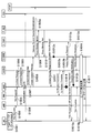
- FIG. 2 is a sequence diagram showing operations of the mobile communication system according to the first embodiment of the present invention.
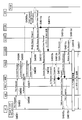
- FIG. 3 is a sequence diagram showing operations of the mobile communication system according to the first embodiment of the present invention.
- FIG. 4 is a sequence diagram showing an operation of the mobile communication system according to the first embodiment of the present invention.
- FIG. 5 is a sequence diagram showing an operation of the mobile communication system according to the first modification of the present invention.
- FIG. 6 is a sequence diagram showing an operation of the mobile communication system according to the second modification of the present invention.
- FIG. 7 is a sequence diagram showing an operation of the mobile communication system according to the second modification of the present invention.
- FIG. 1 is an overall configuration diagram of a mobile communication system according to a first embodiment of the present invention.
- FIG. 2 is a sequence diagram showing operations of the mobile communication system according to the first embodiment of the present invention.
- FIG. 3 is a sequence
- FIG. 8 is a sequence diagram showing operations of the mobile communication system according to the third modification of the present invention.
- FIG. 9 is a sequence diagram showing operations of the mobile communication system according to the fourth modification of the present invention.
- FIG. 10 is a sequence diagram showing operations of the mobile communication system according to the fifth modification of the present invention.
- FIG. 11 is a sequence diagram showing an operation of a conventional mobile communication system.
- Mobile communication system according to the first embodiment of the present invention A mobile communication system according to a first embodiment of the present invention will be described with reference to FIGS.
- the mobile communication system includes an RNC (Radio Network Control Station) that is a radio access network device in UTRAN / GERAN (GSM EDGE Radio Access Network) and an SGSN that is a core network device.
- RNC Radio Network Control Station
- UTRAN / GERAN GSM EDGE Radio Access Network
- SGSN a core network device.
- eNB Radio Base Station
- MME Mobility Management Entity, mobility management node
- HSS Home Subscriber Server, Subscriber Management Server
- PCRF Policy and Charging Ru
- a change from S-GW # 1 to S-GW # 2 for the S-GW that manages the bearer for the UE when the UE connected radio access network is switched from UTRAN to E-UTRAN is not limited to such a case, and the UE connected radio access network is designated as E. -Location registration processing with change of S-GW that manages bearer for UE when switching from UTRAN to UTRAN, and change of S-GW that manages bearer for UE in UTRAN or E-UTRAN
- TAU process / RAU process / HO process, etc. the present invention can be applied to various cases in which “RA” is transmitted to the UE.
- Step S1001 when the UE determines to start the TAU process in Step S1001, the UE transmits “TAU Request” to the eNB in Step S1002.
- step S1003 the eNB transmits “TAU Request” to the MME.
- step S1004 the MME transmits a “Context Request” to the SGSN, and in step S1005, the SGSN transmits a “Context Response” to the MME.
- Step S1006 “Authentication / Security processing” is performed between the UE, MME, and HSS as necessary.
- step S1007 the MME transmits “Context Acknowledge” to the SGSN, and in step S1008, to the S-GW # 2, the user for the UE between the S-GW # 2 and the P-GW. Send a “Create Session Request” requesting to set up a data bearer.
- Step S1008a “Gateway Control Session Establishment Process” is performed between S-GW # 2 and the PCRF.
- step S1009 the S-GW # 2 transmits “Proxy Binding Update” to the P-GW.
- step S1010 the P-GW transmits “Proxy Binding Ack” to the S-GW # 2. Send.
- step S1011 S-GW # 2 transmits “Create Session Response” including “Downlink Data Pending (predetermined information)”, and starts transmission processing of “RA” in step S1012a.
- Downlink Data Pending may be information that explicitly notifies that “RA” is transmitted, or may be information that indicates the presence of downlink data.
- Step S1013a the SGSN transmits “Iu Release Command” to the RNC, and in Step S1013b, the RNC transmits “Iu Release Complete” to the SGSN.
- step S1013c the SGSN transmits “Delete Session Request” to S-GW # 1, and in step S1013d, S-GW # 1 transmits “Delete Session Response” to the SGSN.
- the MME determines to set the S1 bearer / E-RAB for the UE in step S1014.
- step S1015a the MME holds the NAS signaling connection established with the UE without releasing it, and transmits “S1-AP Initial Context Setup Request” including “TAU Accept” to the UE. .
- S1-AP Initial Context Setup Request is a signal that requests to set S1 bearer / E-RAB for UE between S-GW # 2 and eNB under S-GW # 2. is there.
- step S1015a1 the MME transmits “S1-AP Initial Context Setup Request” including “TAU Accept” to the eNB.
- step S1015a2 the eNB “RRC Connection Reconfiguration” including “TAU Accept” is transmitted to the UE.
- TAU Accept is set in the information element “NAS-PDU” in “S1-AP Initial Context Setup Request”.
- step S1015b the UE may transmit “TAU Complete” to the MME. Note that the transmission of the “TAU Complete” may be omitted.
- step S1015b1 the UE transmits “RRC UL Information Transfer” including “TAU Complete” to the eNB, and in step S1015b2, the eNB transmits to the MME. Then, “S1-AP Uplink NAS Transport” including “TAU Complete” is transmitted.
- step S1012b the S-GW # 2 notifies the MME that “RA” is to be transmitted when the S1 bearer / E-RAB for UE is not set with the eNB. “Downlink Data Notification” may be transmitted. Note that the transmission of such “Downlink Data Notification” may be omitted.
- the MME receives a “Downlink Data Notification” when the NAS signaling connection set up with the UE or the timer for releasing the S1 bearer / E-RAB is running, etc. In addition, such a timer may be stopped.
- step S1016 processing for setting the S1 bearer / E-RAB for the UE is performed.
- the UE when the UE receives “RRC Connection Reconfiguration” including “TAU Accept”, the UE transmits “RRCReConnection Reconfiguration Complete” to the eNB in Step 1016a.
- the eNB transmits “S1-AP Initial Context Setup Response” to the MME.
- the MME transmits “Modify Bearer Request” to the S-GW # 2 (not shown), and the S-GW # 2 transmits “Modify Bearer Response” to the MME (not shown). ).
- step S1015b and step S1016 in FIG. 2 may be performed in the order of FIG. 2 or may be performed in parallel. Alternatively, the process of step S1016 may be performed first, and then the process of step S1015b may be performed.
- step S1017 the S-GW # 2 transmits “RA” to the UE via the S1 bearer / E-RAB for the UE.
- a NAS signaling connection for UE “RA” can be transmitted without releasing the.
- Modification 1 With reference to FIG. 5, the mobile communication system which concerns on the modification 1 of this invention is demonstrated.
- the mobile communication system according to the first modification will be described by focusing on differences from the mobile communication system according to the first embodiment.
- PMIP is applied between S-GW # 2 and P-GW, as in the mobile communication system according to the first embodiment described above.
- steps S2001 to S2013d are the same as the operations in steps S1001 to S1013d shown in FIG.
- the MME In response to the reception of “Downlink Data Pending”, the MME holds the NAS signaling connection established with the UE without releasing it in step S2014, and in step S1012b, from the S-GW # 2, “ Upon receiving “Downlink Data Notification”, in step S1015a, it is determined to set the S1 bearer / E-RAB for the UE, and “S1-AP Initial Context Setup Request” including “TAU Accept” is set for the UE. Send.
- the S-GW may notify the MME that the notification is related to the transmission of “RA” by “Downlink Data Notification”.
- the MME may start a timer that waits for reception of “Downlink Data Notification”.
- the MME If the MME cannot receive “Downlink Data Notification” until the timer expires, the MME transmits “TAU Accept” that does not include “S1-AP Context Setup Request” to the UE in step S2015a.
- the MME may thereafter hold the NAS signaling connection for a predetermined time or may immediately disconnect.
- steps S2015a to S2017 are the same as those in steps S1015a to S1017 shown in FIG.
- Modification 2 With reference to FIG.6 and FIG.7, the mobile communication system which concerns on the modification 2 of this invention is demonstrated.
- the mobile communication system according to the second modification will be described with a focus on differences from the mobile communication system according to the first embodiment described above.
- PMIP is applied between S-GW # 2 and P-GW, similarly to the mobile communication system according to the first embodiment described above.
- steps S3001 to S3013d are the same as the operations in steps S1001 to S1013d shown in FIG.
- the MME In response to the reception of “Downlink Data Pending”, the MME holds the NAS signaling connection set with the UE without releasing it in step S3014. In step S3015a, the MME receives “TAU Accept”. ".
- step S3015a1 the MME transmits “S1-AP Downlink NAS Transport” including “TAU Accept” to the eNB.
- step S3015a2 the eNB In response, “RRC DL Information Transfer” including “TAU Accept” is transmitted.
- step S3015b the UE may transmit “TAU Complete” to the MME. Note that the transmission of the “TAU Complete” may be omitted.
- step S3015b1 the UE transmits “RRC UL Information Transfer” including “TAU Complete” to the eNB, and in step S3015b2, the eNB transmits to the MME. Then, “S1-AP UL NAS Transport” including “TAU Complete” is transmitted.
- step S3012c when the MME receives “Downlink Data Notification” notifying that “RA” is to be transmitted from S-GW # 2 in step S3012b, in step S3012c, the SME bearer / E ⁇ The RAB is determined to be set, and “S1-AP Initial Context Setup Request” is transmitted to the eNB.
- step S3016 processing for setting the S1 bearer / E-RAB for the UE is performed.
- step S3012c the MME transmits “S1-AP Initial Context Setup Request” to the eNB.
- the eNB transmits “
- step S3016b the UE transmits “RRC Connection Reconfiguration Complete” to the eNB in response to reception of “RRC Connection Reconfiguration”
- step S3016M the eNB transmits the “RCC Connection Reconfiguration” to the eNB.
- “S1-AP Initial Context Setup Response” is transmitted.
- the MME transmits “Modify Bearer Request” to the S-GW # 2 (not shown), and the S-GW # 2 transmits “Modify Bearer Response” to the MME (not shown). ).
- the MME may release the NAS signaling connection if it does not receive “Downlink Data Notification” in step S3012b within a predetermined time after performing the process of step S3015.
- Modification 3 With reference to FIG. 8, a mobile communication system according to Modification 3 of the present invention is described. Hereinafter, the mobile communication system according to the third modification will be described by focusing on differences from the mobile communication system according to the first embodiment described above.
- GTP is applied between S-GW # 2 and P-GW. To do.
- steps S4001 to S4008 are the same as the operations in steps S1001 to S1008 shown in FIG.
- step S4009 S-GW # 2 transmits “Modify Bearer Request” to P-GW, and in step S4009a, “PCEF Initiated IP-CAN Session Modification Process” is performed between P-GW and PCRF. Is performed.
- step S4010 the P-GW transmits “Modify Bearer Response” including “Downlink Data Pending” to S-GW # 2, and starts transmission processing of “RA” in step S4011a.
- step S4012 S-GW # 2 transmits “Create Session Response” including “Downlink Data Pending”.
- steps S4013a to S4016 are the same as the operations in steps S1013a to S1016 shown in FIG.
- step S4011b when S-GW # 2 receives “RA” from P-GW in step S4011b, when S1 bearer / E-RAB for UE is not set with eNB in step S4011c , “Downlink Data Notification” for notifying that “RA” is to be transmitted may be transmitted to the MME. Note that the transmission of such “Downlink Data Notification” may be omitted.
- the MME receives a “Downlink Data Notification” when the NAS signaling connection set up with the UE or the timer for releasing the S1 bearer / E-RAB is running, etc. In addition, such a timer may be stopped.
- step S4017 S-GW # 2 transmits “RA” received from P-GW to UE via S1 bearer / E-RAB for UE.
- Modification 4 With reference to FIG. 9, a mobile communication system according to Modification 4 of the present invention is described. Hereinafter, the mobile communication system according to the fourth modification will be described by focusing on differences from the mobile communication system according to the third modification described above.
- GTP is applied between the S-GW # 2 and the P-GW, similarly to the mobile communication system according to the third modification described above. .
- steps S5001 to S5013d are the same as the operations in steps S4001 to S4013d shown in FIG.
- the MME In response to the reception of “Downlink Data Pending”, the MME holds the NAS signaling connection established with the UE without releasing it in step S5014. In step S5011c, the MME receives “ Upon receiving “Downlink Data Notification”, in step S5015a, it is determined to set S1 bearer / E-RAB for the UE, and “S1-AP Initial Context Setup Request” including “TAU Accept” is set for the UE. Send.
- the S-GW may notify the MME that the notification is related to the “RA” transmission by “Downlink Data Notification”.
- the MME may start a timer that waits for reception of “Downlink Data Notification”.
- the MME If the MME cannot receive “Downlink Data Notification” until the timer expires, the MME transmits “TAU Accept” that does not include “S1-AP Context Setup Request” to the UE in step S5015a.
- the MME may thereafter hold the NAS signaling connection for a predetermined time or may immediately disconnect.
- steps S5015a to S5017 are the same as the operations in steps S4015a to S4017 shown in FIG.
- Modification 5 With reference to FIG. 10, a mobile communication system according to Modification 5 of the present invention is described. Hereinafter, the mobile communication system according to the fifth modification will be described while focusing on the differences from the mobile communication systems according to the second and third modifications.
- GTP is applied between the S-GW # 2 and the P-GW, similarly to the mobile communication system according to the third modification described above. .
- steps S6001 to S6013d are the same as the operations in steps S4001 to S4013d shown in FIG.
- the MME In response to the reception of “Downlink Data Pending”, the MME holds the NAS signaling connection established with the UE without releasing it in step S6014. In step S6015a, the MME receives “TAU Accept”. ".
- steps S6015a and S6015b are the same as the operations in steps S3015a and S3015b shown in FIG.
- the MME When the MME receives “Downlink Data Notification” notifying that “RA” is transmitted from S-GW # 2 in step S6011c, the MME sets the S1 bearer / E-RAB for UE in step S6011d. And “S1-AP Initial Context Setup Request” is transmitted to the eNB.
- step S6016 processing for setting the S1 bearer / E-RAB for the UE is performed.
- steps S6016 and S6017 are the same as the operations in steps S3016 and S3017 shown in FIG.
- the first feature of this embodiment is that S-GW # 1 (first serving gateway device) of S-GW that manages bearers for UE (mobile station) (for example, S1 bearer / E-RAB and user data bearer) )
- S-GW # 2 second serving gateway device
- “RA notification signal for notifying information relating to IP address assigned to mobile station”
- the S-GW # 2 performs the MME (core network) Device) to send “Downlink Data Pending (predetermined information)” and MME, “Downlink Dat a
- the NAS signaling connection (control bearer) set up with the UE is held without being released, and the eNBs (radio access under S-GW # 2 and S-GW # 2)
- step C the S-GW # 2 transmits “RA” received from the P-GW to the UE via the S1 bearer / E-RAB for the UE. May be.
- the second feature of the present embodiment is that, in the location registration process involving the change from S-GW # 1 to S-GW # 2 of the S-GW that manages the bearer for UE, “RA” In which the S-GW # 2 transmits a “Downlink Data Pending” to the MME in the process of setting the user data bearer for the UE with the P-GW.
- the process B When A and the MME receive “Downlink Data Pending”, the process B that holds the NAS signaling connection established with the UE without releasing it, and the S-GW # 2 When the S1 bearer / E-RAB for UE is not set up between the two, “Downlink Data Notification (downlink) Link data notification signal) "and when the MME receives" Downlink Data Notification ", it requests to set the S1 bearer / E-RAB for the UE" S1-AP Initial Context Setup Request "
- the gist of the present invention is that the process D includes the process D and the S-GW # 2 includes the process E that transmits “RA” to the UE via the S1 bearer / E-RAB for the UE.
- step E the S-GW # 2 transmits “RA” received from the P-GW to the UE via the S1 bearer / E-RAB for the UE. May be.
- the operations of the UE, eNB, RNC, MME, SGSN, S-GW # 1, S-GW # 2, P-GW, PCRF, HSS, etc. may be implemented by hardware, It may be implemented by a software module to be executed, or may be implemented by a combination of both.
- the software modules include RAM (Random Access Memory), flash memory, ROM (Read Only Memory), EPROM (Erasable Programmable ROM), EEPROM (Electronically Erasable and Programmable, Removable ROM, Hard Disk, and Removable ROM).
- RAM Random Access Memory
- flash memory ROM (Read Only Memory)
- EPROM Erasable Programmable ROM
- EEPROM Electrically Erasable and Programmable, Removable ROM, Hard Disk, and Removable ROM.
- it may be provided in a storage medium of an arbitrary format such as a CD-ROM.
- the storage medium is connected to the processor so that the processor can read and write information from and to the storage medium. Further, such a storage medium may be integrated in the processor. Such a storage medium and processor may be provided in the ASIC. Such an ASIC may be provided in a UE, eNB, RNC, MME, SGSN, S-GW # 1, S-GW # 2, P-GW, PCRF, HSS, or the like. Further, the storage medium and the processor may be provided in the UE, eNB, RNC, MME, SGSN, S-GW # 1, S-GW # 2, P-GW, PCRF, HSS, etc. as discrete components. .
- RA when “RA” is transmitted to the UE in response to access from the UE, induction of “Paging” is prevented, and efficient “RA” transmission is performed. It is possible to provide a mobile communication method that makes it possible.
- UE ... mobile station eNB ... radio base station RNC ... radio network controller MME ... mobility management node SGSN ... packet switch S-GW # 1, S-GW # 2 ... serving gateway device P-GW ... packet data network gateway device PCRF ... Policy and charging rule server device HSS ... Subscriber management server device
Landscapes
- Engineering & Computer Science (AREA)
- Computer Networks & Wireless Communication (AREA)
- Signal Processing (AREA)
- Mobile Radio Communication Systems (AREA)
Abstract
UEからのアクセスを契機にUEに対して「RA」を送信する場合における「Paging」の誘発を防止し、効率的な「RA」の送信を行う。本実施形態に係る移動通信方法は、S-GW#2が、P-GWとの間でUE用のユーザデータベアラを設定する処理において、MMEに対して、「Downlink Data Pending」を送信する工程Aと、MMEが、「Downlink Data Pending」を受信した場合、UEとの間で設定されているNASシグナリングコネクションを開放することなく保持すると共に、S-GW#2とS-GW#2配下のeNBとの間でUE用のS1ベアラ/E-RABを設定するように要求する「Initial Cotext Setup Request」を送信する工程Bと、MMEが、UE用のS1ベアラ/E-RABを介して、UEに対して、「RA」を送信する工程Cとを有する。
Description
本発明は、移動通信方法に関する。
非特許文献1に記載のGTP(GPRS Tunneling Protocol)が適用されているEPC(Evolved Packet Core)ネットワークでは、「RA(Router Advertisement、ルータ通知信号)」が、P-GW(PDN-Gateway、パケットデータネットワークゲートウェイ装置)から、UE(User Equipment、移動局)に通知されるように構成されている。
「RA」は、UEに割り当てる「IPv6 Prefix」や、かかる「IPv6 Prefix」が有効である時間を示す「router lifetime」や、「default gateway情報(パケット転送情報)」を含む。
UEは、定期的に「RA」を受信することで、UEが保持するIPv6アドレスの有効性について更新するように構成されている。
すなわち、UEは、「RA」を受信した場合、かかる「RA」に含まれる「router lifetime」に基づいて「Router lifetime(所定タイマ)」を設定して、かかる「RA」に含まれる「default gateway情報」を保持するように構成されている。
ここで、UEは、かかる「Router lifetime」が満了するまでに「RA」を受信した場合には、受信した「RA」に基づいて、保持するIPv6アドレスの有効性について更新し、かかる「default gateway情報」を更新するように構成されている。
一方、UEは、UEが保持するIPv6アドレスが有効でないと判断した場合、すなわち、「Router lifetime」が満了するまでに「RA」を受信しなかった場合、保持する「default gateway情報」を削除するように構成されている。
言い換えると、かかるUEは、「RA」で通知された「Router lifetime(例えば、18時間)」が満了するまで、「default gateway情報」を保持し、「Router lifetime」が満了した後に、「default gateway情報」を削除するように構成されている。
ここで、「Router lifetime」は、UEによって保持されるタイマであり、デフォルト値として、「MaxRtrAdvInterval(ネットワーク側タイマ)」の3倍の時間が定義されている(例えば、非特許文献2参照)。
また、「MaxRtrAdvInterval」は、移動局UEの接続するP-GWによって保持されるタイマ(最大RA送信間隔)であり、デフォルト値として、「21600秒(6時間)」が定義されている(例えば、非特許文献3参照)。
同様に、非特許文献4に記載のPMIP(Proxy Mobile IP)が適用されているEPCネットワークでは、「RA」が、S-GW(Serving Gateway、サービングゲートウェイ装置)から、UEに通知されるように構成されている。
ここで、「MaxRtrAdvInterval」は、移動局UEの接続するS-GWによって保持されるタイマ(最大RA送信間隔)であり、デフォルト値として、「21600秒(6時間)」が定義されている(例えば、非特許文献3参照)。
また、上述のPMIPが適用されているEPCネットワークにおいて、UEの移動に伴い、TAU(Tracking Area Update)処理やRAU(Routing Area Update)処理やHO(Handover)処理が実施され、UE用のベアラを管理するS-GWが、S-GW#1からS-GW#2に変更になった場合、S-GW#2が、UEに対して「RA」を送信することができるように構成されている。
3GPP TS23.401
RFC4861 6.2.1
3GPP TS29.061
3GPP TS23.402
図11に、UEの接続先無線アクセスネットワーク(RAT:Radio Access Technology)をUTRAN(Universal Terrestrial Radio Access Network)からE-UTRAN(Evolved Universal Terrestrial Radio Access Network)に切り替えた場合、UE用のベアラを管理するS-GWのS-GW#1からS-GW#2への変更を伴う位置登録処理において、UEに対して「RA」を送信する動作について示す。
図11に示すように、MMEは、ステップS111において、S-GWから「Create Session Response」を受信し、ステップS115において、UEに対して「TAU Accept」を送信した後、或いは、ステップS117において、UEから「TAU Complete」を受信した後、ステップS118において、MMEとUEとの間で設定されているNASシグナリングコネクションが開放される。
なお、S-GW#2は、ステップS111bにおいて、「RA」の送信処理を開始し、ステップ116において、配下のeNBとの間でUE用のS1ベアラ/E-RAB(EUTRAN-Radio Access Bearer)が設定されていないため、MMEに対して、「RA」を送信することを通知する「Downlink Data Notification(下りリンクデータ通知信号)」を送信する。
ここで、MMEは、かかる「Downlink Data Notification」を受信した場合、ステップS119において、MMEとUEとの間でNASシグナリングコネクションが設定されていないことを検出し、ステップS120において、UE宛ての「Paging(ページング信号)」を送信する。
すなわち、従来の移動通信システムでは、UEからのアクセスを契機にUEに対して「RA」を送信するケース、例えば、UE用のベアラを管理するS-GWの変更を伴う位置登録処理を契機にUEに対して「RA」を送信するケースでは、一旦、UE用のNASシグナリングコネクションを開放した後、「Paging」を送信することによって、再度、UE用のNASシグナリングコネクションを設定し、「RA」の転送に必要なS1ベアラ/E-RABを設定するように構成されている。
したがって、UEからのアクセスを契機にUEに対して「RA」を送信する場合、「Paging」を誘発することになり、効率的な「RA」の送信を行うことができないという問題点があった。
そこで、本発明は、上述の課題に鑑みてなされたものであり、UEからのアクセスを契機にUEに対して「RA」を送信する場合における「Paging」の誘発を防止し、効率的な「RA」の送信を行うことを可能とする移動通信方法を提供することを目的とする。
本発明の第1の特徴は、移動局用のベアラを管理するサービングゲートウェイ装置の第1サービングゲートウェイ装置から第2サービングゲートウェイ装置への変更を伴う位置登録処理において、該移動局に対して、該移動局に割り当てるIPアドレスに係る情報を通知する通知信号を送信する移動通信方法であって、前記第2サービングゲートウェイ装置が、パケットデータネットワークゲートウェイ装置との間で前記移動局用の第1ユーザベアラを設定する処理において、該第2サービングゲートウェイ装置に接続されているコアネットワーク装置に対して、所定情報を送信する工程Aと、前記コアネットワーク装置が、前記所定情報を受信した場合、前記移動局との間で設定されている制御ベアラを開放することなく保持すると共に、前記第2サービングゲートウェイ装置と該第2サービングゲートウェイ装置配下の無線アクセスネットワーク装置との間で該移動局用の第2ユーザベアラを設定するように要求する設定要求信号を送信する工程Bと、前記第2サービングゲートウェイ装置が、前記第2ユーザベアラを介して、前記移動局に対して、前記通知信号を送信する工程Cとを有することを要旨とする。
本発明の第2の特徴は、移動局用のベアラを管理するサービングゲートウェイ装置の第1サービングゲートウェイ装置から第2サービングゲートウェイ装置への変更を伴う位置登録処理において、該移動局に対して、該移動局に割り当てるIPアドレスに係る情報を通知する通知信号を送信する移動通信方法であって、前記第2サービングゲートウェイ装置が、パケットデータネットワークゲートウェイ装置との間で前記移動局用の第1ユーザベアラを設定する処理において、該第2サービングゲートウェイ装置に接続されているコアネットワーク装置に対して、所定情報を送信する工程Aと、前記コアネットワーク装置が、前記所定情報を受信した場合、前記移動局との間で設定されている制御ベアラを開放することなく保持する工程Bと、前記第2サービングゲートウェイ装置が、配下の無線アクセスネットワーク装置との間で前記移動局用の第2ユーザベアラが設定されていない場合に、前記コアネットワーク装置に対して、下りリンクデータ通知信号を送信する工程Cと、前記コアネットワーク装置が、前記下りリンクデータ通知信号を受信した場合、前記第2ユーザベアラを設定するように要求する設定要求信号を送信する工程Dと、前記第2サービングゲートウェイ装置が、前記第2ユーザベアラを介して、前記移動局に対して、前記通知信号を送信する工程Eとを有することを要旨とする。
(本発明の第1の実施形態に係る移動通信システム)
図1乃至図4を参照して、本発明の第1の実施形態に係る移動通信システムについて説明する。
図1乃至図4を参照して、本発明の第1の実施形態に係る移動通信システムについて説明する。
図1に示すように、本実施形態に係る移動通信システムは、UTRAN/GERAN(GSM EDGE Radio Access Network)内の無線アクセスネットワーク装置であるRNC(無線回線制御局)や、コアネットワーク装置であるSGSN(Serving GPRS Support Node、パケット交換機)や、E-UTARN内の無線アクセスネットワーク装置であるeNB(無線基地局)や、コアネットワーク装置であるMME(Mobility Management Entity、移動管理ノード)や、S-GW#1や、S-GW#2や、P-GWや、HSS(Home Subscriber Server、加入者管理サーバ)や、PCRF(Policy and Charging Rules Function)等を具備している。
なお、本実施形態に係る移動通信システムでは、S-GW#2とP-GWとの間で、PMIPが適用されているものとする。
以下、本実施形態では、UEの接続先無線アクセスネットワークをUTRANからE-UTRANに切り替えた場合のUE用のベアラを管理するS-GWについてS-GW#1からS-GW#2への変更を伴う位置登録処理において、UEに対して「RA」を送信するケースを例に挙げて説明するが、本発明は、かかるケースに限定されるものではなく、UEの接続先無線アクセスネットワークをE-UTRANからUTRANへの切り替えた場合のUE用のベアラを管理するS-GWの変更を伴う位置登録処理や、UTRAN内或いはE-UTRAN内においてUE用のベアラを管理するS-GWの変更を伴う各種処理(TAU処理/RAU処理/HO処理等)において、UEに対して「RA」を送信する様々なケースに適用可能である。
以下、図2乃至図4を参照して、本実施形態に係る移動通信システムにおいて、UE用のベアラを管理するS-GWのS-GW#1からS-GW#2への変更を伴う位置登録処理においてUEに対して「RA」を送信する動作について説明する。
図3に示すように、UEは、ステップS1001において、TAU処理を開始することを決定すると、ステップS1002において、eNBに対して、「TAU Request」を送信する。
ステップS1003において、eNBは、MMEに対して、「TAU Request」を送信する。
ステップS1004において、MMEは、SGSNに対して、「Context Request」を送信し、ステップS1005において、SGSNは、MMEに対して、「Context Response」を送信する。
ステップS1006において、UEとMMEとHSSとの間で、「Authentication/Security処理」が必要に応じて行われる。
MMEは、ステップS1007において、SGSNに対して、「Context Acknowledge」を送信し、ステップS1008において、S-GW#2に対して、S-GW#2とP-GWとの間でUE用のユーザデータベアラを設定することを要求する「Create Session Request」を送信する。
ステップS1008aにおいて、S-GW#2とPCRFとの間で、「Gateway Control Session Establishment処理」が行われる。
ステップS1009において、S-GW#2は、P-GWに対して、「Proxy Binding Update」を送信し、ステップS1010において、P-GWは、S-GW#2に対して、「Proxy Binding Ack」を送信する。
S-GW#2は、ステップS1011において、「Downlink Data Pending(所定情報)」を含む「Create Session Response」を送信し、ステップS1012aにおいて、「RA」の送信処理を開始する。
ここで、「Downlink Data Pending」は、「RA」を送信することを明示的に通知する情報であってもよいし、下りデータの存在を示す情報であってもよい。
ステップS1013aにおいて、SGSNは、RNCに対して、「Iu Release Command」を送信し、ステップS1013bにおいて、RNCは、SGSNに対して、「Iu Release Complete」を送信する。
ステップS1013cにおいて、SGSNは、S-GW#1に対して、「Delete Session Request」を送信し、ステップS1013dにおいて、S-GW#1は、SGSNに対して、「Delete Session Response」を送信する。
MMEは、「Downlink Data Pending」の受信に応じて、ステップS1014において、UE用のS1ベアラ/E-RABを設定することを決定する。
ステップS1015aにおいて、MMEは、UEとの間で設定されているNASシグナリングコネクションを開放することなく保持し、UEに対して、「TAU Accept」を含む「S1-AP Initial Context Setup Request」を送信する。
ここで、「S1-AP Initial Context Setup Request」は、S-GW#2とS-GW#2配下のeNBとの間でUE用のS1ベアラ/E-RABを設定するように要求する信号である。
具体的には、図3に示すように、ステップS1015a1において、MMEは、eNBに対して、「TAU Accept」を含む「S1-AP Initial Context Setup Request」を送信し、ステップS1015a2において、eNBは、UEに対して、「TAU Accept」を含む「RRC Connection Reconfiguration」を送信する。
例えば、図4に示すように、「TAU Accept」は、「S1-AP Initial Context Setup Request」内の情報要素「NAS-PDU」内に設定される。
図2に戻り、ステップS1015bにおいて、UEは、MMEに対して、「TAU Complete」を送信してもよい。なお、かかる「TAU Complete」の送信は省略されてもよい。
具体的には、図3に示すように、ステップS1015b1において、UEは、eNBに対して、「TAU Complete」を含む「RRC UL Information Transfer」を送信し、ステップS1015b2において、eNBは、MMEに対して、「TAU Complete」を含む「S1-AP Uplink NAS Transport」を送信する。
なお、ステップS1012bにおいて、S-GW#2は、eNBとの間でUE用のS1ベアラ/E-RABが設定されていない場合に、MMEに対して、「RA」を送信することを通知する「Downlink Data Notification」を送信してもよい。なお、かかる「Downlink Data Notification」の送信は省略されてもよい。
ここで、MMEは、かかる「Downlink Data Notification」を受信しても、特段の動作を実施しない。
ただし、MMEは、UEとの間で設定されているNASシグナリングコネクション或いはS1ベアラ/E-RABを開放するためのタイマ等が起動している場合には、かかる「Downlink Data Notification」を受信した場合に、かかるタイマを停止してもよい。
ステップS1016において、UE用のS1ベアラ/E-RABを設定する処理が行われる。
具体的には、図3に示すように、UEは、「TAU Accept」を含む「RRC Connection Reconfiguration」を受信すると、ステップ1016aにおいて、eNBに対して、「RRC Connection Reconfiguration Complete」を送信し、ステップS1016bにおいて、eNBは、MMEに対して、「S1-AP Initial Context Setup Response」を送信する。
また、MMEは、S-GW#2に対して、「Modify Bearer Request」を送信し(不図示)、S-GW#2は、MMEに対して、「Modify Bearer Response」を送信する(不図示)。
この結果、UE用のS1ベアラ/E-RABの設定が完了する。
なお、図2におけるステップS1015b及びステップS1016の処理は、図2の順序の通りに実施されてもよいし、並列して実施されてもよい。或いは、ステップS1016の処理が先に実施され、その後、ステップS1015bの処理が実施されてもよい。
図2に戻り、ステップS1017において、S-GW#2は、UEに対して、UE用のS1ベアラ/E-RABを介して、「RA」を送信する。
本実施形態に係る移動通信システムによれば、UE用のベアラを管理するS-GWのS-GW#1からS-GW#2への変更を伴う位置登録処理において、UE用のNASシグナリングコネクションを開放することなく、「RA」を送信することができる。
(変更例1)
図5を参照して、本発明の変更例1に係る移動通信システムについて説明する。以下、本変更例1に係る移動通信システムについて、上述の第1の実施形態に係る移動通信システムとの相違点に着目して説明する。
図5を参照して、本発明の変更例1に係る移動通信システムについて説明する。以下、本変更例1に係る移動通信システムについて、上述の第1の実施形態に係る移動通信システムとの相違点に着目して説明する。
なお、本変更例1に係る移動通信システムでは、上述の第1の実施形態に係る移動通信システムと同様に、S-GW#2とP-GWとの間で、PMIPが適用されているものとする。
以下、図5を参照して、本変更例1に係る移動通信システムにおいて、UE用のベアラを管理するS-GWのS-GW#1からS-GW#2への変更を伴う位置登録処理においてUEに対して「RA」を送信する動作について説明する。
図5に示すように、ステップS2001乃至S2013dの動作は、図2に示すステップS1001乃至S1013dの動作と同一である。
MMEは、「Downlink Data Pending」の受信に応じて、ステップS2014において、UEとの間で設定されているNASシグナリングコネクションを開放することなく保持し、ステップS1012bにおいて、S-GW#2から、「Downlink Data Notification」を受信すると、ステップS1015aにおいて、UE用のS1ベアラ/E-RABを設定することを決定し、UEに対して、「TAU Accept」を含む「S1-AP Initial Context Setup Request」を送信する。
ここで、S-GWは、「Downlink Data Notification」により、「RA」の送信に係る通知であることをMMEに対して通知してもよい。
また、MMEは、「Downlink Data Pending」を受信した場合、「Downlink Data Notification」の受信を待つタイマを起動してもよい。
MMEは、かかるタイマが満了するまでに、「Downlink Data Notification」を受信できない場合、ステップS2015aにおいて、UEに対して、「S1-AP Context Setup Request」を含まない「TAU Accept」を送信する。
かかる場合、MMEは、その後、所定時間、NASシグナリングコネクションを保持してもよいし、即座に切断してもよい。
以下、ステップS2015a乃至S2017の動作は、図2に示すステップS1015a乃至S1017の動作と同一である。
(変更例2)
図6及び図7を参照して、本発明の変更例2に係る移動通信システムについて説明する。以下、本変更例2に係る移動通信システムについて、上述の第1の実施形態に係る移動通信システムとの相違点に着目して説明する。
図6及び図7を参照して、本発明の変更例2に係る移動通信システムについて説明する。以下、本変更例2に係る移動通信システムについて、上述の第1の実施形態に係る移動通信システムとの相違点に着目して説明する。
なお、本変更例2に係る移動通信システムでは、上述の第1の実施形態に係る移動通信システムと同様に、S-GW#2とP-GWとの間で、PMIPが適用されているものとする。
以下、図6及び図7を参照して、本変更例2に係る移動通信システムにおいて、UE用のベアラを管理するS-GWのS-GW#1からS-GW#2への変更を伴う位置登録処理においてUEに対して「RA」を送信する動作について説明する。
図6に示すように、ステップS3001乃至S3013dの動作は、図2に示すステップS1001乃至S1013dの動作と同一である。
MMEは、「Downlink Data Pending」の受信に応じて、 ステップS3014において、UEとの間で設定されているNASシグナリングコネクションを開放することなく保持し、ステップS3015aにおいて、UEに対して、「TAU Accept」を送信する。
具体的には、図7に示すように、ステップS3015a1において、MMEは、eNBに対して、「TAU Accept」を含む「S1-AP Downlink NAS Transport」を送信し、ステップS3015a2において、eNBは、UEに対して、「TAU Accept」を含む「RRC DL Information Transfer」を送信する。
ステップS3015bにおいて、UEは、MMEに対して、「TAU Complete」を送信してもよい。なお、かかる「TAU Complete」の送信は省略されてもよい。
具体的には、図7に示すように、ステップS3015b1において、UEは、eNBに対して、「TAU Complete」を含む「RRC UL Information Transfer」を送信し、ステップS3015b2において、eNBは、MMEに対して、「TAU Complete」を含む「S1-AP UL NAS Transport」を送信する。
図6に戻り、MMEは、ステップS3012bにおいて、S-GW#2から、「RA」を送信することを通知する「Downlink Data Notification」を受信すると、ステップS3012cにおいて、UE用のS1ベアラ/E-RABを設定することを決定し、eNBに対して、「S1-AP Initial Context Setup Request」を送信する。
ステップS3016において、UE用のS1ベアラ/E-RABを設定する処理が行われる。
具体的には、図7に示すように、ステップS3012cにおいて、MMEは、eNBに対して、「S1-AP Initial Context Setup Request」を送信し、ステップS3016aにおいて、eNBは、UEに対して、「RRC Connection Reconfiguration」を送信し、ステップS3016bにおいて、UEは、「RRC Connection Reconfiguration」の受信に応じて、eNBに対して、「RRC Connection Reconfiguration Complete」を送信し、ステップS3016cにおいて、eNBは、MMEに対して、「S1-AP Initial Context Setup Response」を送信する。
また、MMEは、S-GW#2に対して、「Modify Bearer Request」を送信し(不図示)、S-GW#2は、MMEに対して、「Modify Bearer Response」を送信する(不図示)。
この結果、UE用のS1ベアラ/E-RABの設定が完了する。
なお、MMEは、ステップS3015の処理を実施した後、所定時間内に、ステップS3012bにおいて、「Downlink Data Notification」を受信しなかった場合、NASシグナリングコネクションを開放してもよい。
(変更例3)
図8を参照して、本発明の変更例3に係る移動通信システムについて説明する。以下、本変更例3に係る移動通信システムについて、上述の第1の実施形態に係る移動通信システムとの相違点に着目して説明する。
図8を参照して、本発明の変更例3に係る移動通信システムについて説明する。以下、本変更例3に係る移動通信システムについて、上述の第1の実施形態に係る移動通信システムとの相違点に着目して説明する。
なお、本変更例3に係る移動通信システムでは、上述の第1の実施形態に係る移動通信システムと異なり、S-GW#2とP-GWとの間で、GTPが適用されているものとする。
以下、図8を参照して、本変更例3に係る移動通信システムにおいて、UE用のベアラを管理するS-GWのS-GW#1からS-GW#2への変更を伴う位置登録処理においてUEに対して「RA」を送信する動作について説明する。
図8に示すように、ステップS4001乃至S4008の動作は、図2に示すステップS1001乃至S1008の動作と同一である。
ステップS4009において、S-GW#2は、P-GWに対して、「Modify Bearer Request」を送信し、ステップS4009aにおいて、P-GWとPCRFとの間で、「PCEF Initiated IP-CAN Session Modification処理」が行われる。
P-GWは、ステップS4010において、S-GW#2に対して、「Downlink Data Pending」を含む「Modify Bearer Response」を送信し、ステップS4011aにおいて、「RA」の送信処理を開始する。
ステップS4012において、S-GW#2は、「Downlink Data Pending」を含む「Create Session Response」を送信する。
ステップS4013a乃至S4016の動作は、図2に示すステップS1013a乃至S1016の動作と同一である。
なお、S-GW#2は、ステップS4011bにおいて、P-GWから「RA」を受信した場合、ステップS4011cにおいて、eNBとの間でUE用のS1ベアラ/E-RABが設定されていない場合に、MMEに対して、「RA」を送信することを通知する「Downlink Data Notification」を送信してもよい。なお、かかる「Downlink Data Notification」の送信は省略されてもよい。
ここで、MMEは、かかる「Downlink Data Notification」を受信しても、特段の動作を実施しない。
ただし、MMEは、UEとの間で設定されているNASシグナリングコネクション或いはS1ベアラ/E-RABを開放するためのタイマ等が起動している場合には、かかる「Downlink Data Notification」を受信した場合に、かかるタイマを停止してもよい。
ステップS4017において、S-GW#2は、UEに対して、UE用のS1ベアラ/E-RABを介して、P-GWから受信した「RA」を送信する。
(変更例4)
図9を参照して、本発明の変更例4に係る移動通信システムについて説明する。以下、本変更例4に係る移動通信システムについて、上述の変更例3に係る移動通信システムとの相違点に着目して説明する。
図9を参照して、本発明の変更例4に係る移動通信システムについて説明する。以下、本変更例4に係る移動通信システムについて、上述の変更例3に係る移動通信システムとの相違点に着目して説明する。
なお、本変更例4に係る移動通信システムでは、上述の変更例3に係る移動通信システムと同様に、S-GW#2とP-GWとの間で、GTPが適用されているものとする。
以下、図9を参照して、本変更例4に係る移動通信システムにおいて、UE用のベアラを管理するS-GWのS-GW#1からS-GW#2への変更を伴う位置登録処理においてUEに対して「RA」を送信する動作について説明する。
図9に示すように、ステップS5001乃至S5013dの動作は、図8に示すステップS4001乃至S4013dの動作と同一である。
MMEは、「Downlink Data Pending」の受信に応じて、ステップS5014において、UEとの間で設定されているNASシグナリングコネクションを開放することなく保持し、ステップS5011cにおいて、S-GW#2から、「Downlink Data Notification」を受信すると、ステップS5015aにおいて、UE用のS1ベアラ/E-RABを設定することを決定し、UEに対して、「TAU Accept」を含む「S1-AP Initial Context Setup Request」を送信する。
ここで、S-GWは、「Downlink Data Notification」により、「RA」送信に係る通知であることをMMEに対して通知してもよい。
また、MMEは、「Downlink Data Pending」を受信した場合、「Downlink Data Notification」の受信を待つタイマを起動してもよい。
MMEは、かかるタイマが満了するまでに、「Downlink Data Notification」を受信できない場合、ステップS5015aにおいて、UEに対して、「S1-AP Context Setup Request」を含まない「TAU Accept」を送信する。
かかる場合、MMEは、その後、所定時間、NASシグナリングコネクションを保持してもよいし、即座に切断してもよい。
以下、ステップS5015a乃至S5017の動作は、図8に示すステップS4015a乃至S4017の動作と同一である。
(変更例5)
図10を参照して、本発明の変更例5に係る移動通信システムについて説明する。以下、本変更例5に係る移動通信システムについて、上述の変更例2及び3に係る移動通信システムとの相違点に着目して説明する。
図10を参照して、本発明の変更例5に係る移動通信システムについて説明する。以下、本変更例5に係る移動通信システムについて、上述の変更例2及び3に係る移動通信システムとの相違点に着目して説明する。
なお、本変更例5に係る移動通信システムでは、上述の変更例3に係る移動通信システムと同様に、S-GW#2とP-GWとの間で、GTPが適用されているものとする。
以下、図10を参照して、本変更例5に係る移動通信システムにおいて、UE用のベアラを管理するS-GWのS-GW#1からS-GW#2への変更を伴う位置登録処理においてUEに対して「RA」を送信する動作について説明する。
図10に示すように、ステップS6001乃至S6013dの動作は、図8に示すステップS4001乃至S4013dの動作と同一である。
MMEは、「Downlink Data Pending」の受信に応じて、 ステップS6014において、UEとの間で設定されているNASシグナリングコネクションを開放することなく保持し、ステップS6015aにおいて、UEに対して、「TAU Accept」を送信する。
ここで、ステップS6015a及びS6015bの動作は、図6に示すステップS3015a及びS3015bの動作と同一である。
MMEは、ステップS6011cにおいて、S-GW#2から、「RA」を送信することを通知する「Downlink Data Notification」を受信すると、ステップS6011dにおいて、UE用のS1ベアラ/E-RABを設定することを決定し、eNBに対して、「S1-AP Initial Context Setup Request」を送信する。
ステップS6016において、UE用のS1ベアラ/E-RABを設定する処理が行われる。
ここで、ステップS6016及びS6017の動作は、図6に示すステップS3016及びS3017の動作と同一である。
以上に述べた本実施形態の特徴は、以下のように表現されていてもよい。
本実施形態の第1の特徴は、UE(移動局)用のベアラ(例えば、S1ベアラ/E-RABやユーザデータベアラ)を管理するS-GWのS-GW#1(第1サービングゲートウェイ装置)からS-GW#2(第2サービングゲートウェイ装置)への変更を伴う位置登録処理において、UEに対して、「RA(移動局に割り当てるIPアドレスに係る情報を通知する通知信号)」を送信する移動通信方法であって、S-GW#2が、P-GW(パケットデータネットワークゲートウェイ装置)との間でUE用のユーザデータベアラ(第1ユーザベアラ)を設定する処理において、MME(コアネットワーク装置)に対して、「Downlink Data Pending(所定情報)」を送信する工程Aと、MMEが、「Downlink Data Pending」を受信した場合、UEとの間で設定されているNASシグナリングコネクション(制御ベアラ)を開放することなく保持すると共に、S-GW#2とS-GW#2配下のeNB(無線アクセスネットワーク装置)との間でUE用のS1ベアラ/E-RAB(第2ユーザベアラ)を設定するように要求する「S1-AP Initial Cotext Setup Request(設定要求信号)」を送信する工程Bと、S-GW#2が、UE用のS1ベアラ/E-RABを介して、UEに対して、「RA」を送信する工程Cとを有することを要旨とする。
本実施形態の第1の特徴において、工程Cにおいて、S-GW#2は、UE用のS1ベアラ/E-RABを介して、UEに対して、P-GWから受信した「RA」を送信してもよい。
本実施形態の第2の特徴は、UE用のベアラを管理するS-GWのS-GW#1からS-GW#2への変更を伴う位置登録処理において、UEに対して、「RA」を送信する移動通信方法であって、S-GW#2が、P-GWとの間でUE用のユーザデータベアラを設定する処理において、MMEに対して、「Downlink Data Pending」を送信する工程Aと、MMEが、「Downlink Data Pending」を受信した場合、UEとの間で設定されているNASシグナリングコネクションを開放することなく保持する工程Bと、S-GW#2が、配下のeNBとの間でUE用のS1ベアラ/E-RABが設定されていない場合に、MMEに対して、「Downlink Data Notification(下りリンクデータ通知信号)」を送信する工程Cと、MMEが、「Downlink Data Notification」を受信した場合、UE用のS1ベアラ/E-RABを設定するように要求する「S1-AP Initial Cotext Setup Request」を送信する工程Dと、S-GW#2が、UE用のS1ベアラ/E-RABを介して、UEに対して、「RA」を送信する工程Eとを有することを要旨とする。
本実施形態の第2の特徴において、工程Eにおいて、S-GW#2は、UE用のS1ベアラ/E-RABを介して、UEに対して、P-GWから受信した「RA」を送信してもよい。
なお、上述のUEやeNBやRNCやMMEやSGSNやS-GW#1やS-GW#2やP-GWやPCRFやHSS等の動作は、ハードウェアによって実施されてもよいし、プロセッサによって実行されるソフトウェアモジュールによって実施されてもよいし、両者の組み合わせによって実施されてもよい。
ソフトウェアモジュールは、RAM(Random Access Memory)や、フラッシュメモリや、ROM(Read Only Memory)や、EPROM(Erasable Programmable ROM)や、EEPROM(Electronically Erasable and Programmable ROM)や、レジスタや、ハードディスクや、リムーバブルディスクや、CD-ROMといった任意形式の記憶媒体内に設けられていてもよい。
かかる記憶媒体は、プロセッサが当該記憶媒体に情報を読み書きできるように、当該プロセッサに接続されている。また、かかる記憶媒体は、プロセッサに集積されていてもよい。また、かかる記憶媒体及びプロセッサは、ASIC内に設けられていてもよい。かかるASICは、UEやeNBやRNCやMMEやSGSNやS-GW#1やS-GW#2やP-GWやPCRFやHSS等内に設けられていてもよい。また、かかる記憶媒体及びプロセッサは、ディスクリートコンポーネントとしてUEやeNBやRNCやMMEやSGSNやS-GW#1やS-GW#2やP-GWやPCRFやHSS等内に設けられていてもよい。
以上、上述の実施形態を用いて本発明について詳細に説明したが、当業者にとっては、本発明が本明細書中に説明した実施形態に限定されるものではないということは明らかである。本発明は、請求の範囲の記載により定まる本発明の趣旨及び範囲を逸脱することなく修正及び変更態様として実施することができる。従って、本明細書の記載は、例示説明を目的とするものであり、本発明に対して何ら制限的な意味を有するものではない。
なお、日本国特許出願第2011-066092号(2011年3月24日出願)の全内容が、参照により、本願明細書に組み込まれている。
以上説明したように、本発明によれば、UEからのアクセスを契機にUEに対して「RA」を送信する場合における「Paging」の誘発を防止し、効率的な「RA」の送信を行うことを可能とする移動通信方法を提供することができる。
UE…移動局
eNB…無線基地局
RNC…無線回線制御局
MME…移動管理ノード
SGSN…パケット交換機
S-GW#1、S-GW#2…サービングゲートウェイ装置
P-GW…パケットデータネットワークゲートウェイ装置
PCRF…ポリシー及び課金ルールサーバ装置
HSS…加入者管理サーバ装置
eNB…無線基地局
RNC…無線回線制御局
MME…移動管理ノード
SGSN…パケット交換機
S-GW#1、S-GW#2…サービングゲートウェイ装置
P-GW…パケットデータネットワークゲートウェイ装置
PCRF…ポリシー及び課金ルールサーバ装置
HSS…加入者管理サーバ装置
Claims (4)
- 移動局用のベアラを管理するサービングゲートウェイ装置の第1サービングゲートウェイ装置から第2サービングゲートウェイ装置への変更を伴う該移動局の位置登録処理において、該移動局に対して、該移動局に割り当てるIPアドレスに係る情報を通知する通知信号を送信する移動通信方法であって、
前記第2サービングゲートウェイ装置が、パケットデータネットワークゲートウェイ装置との間で前記移動局用の第1ユーザベアラを設定する処理において、該第2サービングゲートウェイ装置に接続されているコアネットワーク装置に対して、所定情報を送信する工程Aと、
前記コアネットワーク装置が、前記所定情報を受信した場合、前記移動局との間で設定されている制御ベアラを開放することなく保持すると共に、前記第2サービングゲートウェイ装置と該第2サービングゲートウェイ装置配下の無線アクセスネットワーク装置との間で該移動局用の第2ユーザベアラを設定するように要求する設定要求信号を送信する工程Bと、
前記第2サービングゲートウェイ装置が、前記第2ユーザベアラを介して、前記移動局に対して、前記通知信号を送信する工程Cとを有することを特徴とする移動通信方法。 - 前記工程Cにおいて、前記第2サービングゲートウェイ装置は、前記第2ユーザベアラを介して、前記移動局に対して、前記パケットデータネットワークゲートウェイ装置から受信した前記通知信号を送信することを特徴とする請求項1に記載の移動通信方法。
- 移動局用のベアラを管理するサービングゲートウェイ装置の第1サービングゲートウェイ装置から第2サービングゲートウェイ装置への変更を伴う該移動局の位置登録処理において、該移動局に対して、該移動局に割り当てるIPアドレスに係る情報を通知する通知信号を送信する移動通信方法であって、
前記第2サービングゲートウェイ装置が、パケットデータネットワークゲートウェイ装置との間で前記移動局用の第1ユーザベアラを設定する処理において、該第2サービングゲートウェイ装置に接続されているコアネットワーク装置に対して、所定情報を送信する工程Aと、
前記コアネットワーク装置が、前記所定情報を受信した場合、前記移動局との間で設定されている制御ベアラを開放することなく保持する工程Bと、
前記第2サービングゲートウェイ装置が、配下の無線アクセスネットワーク装置との間で前記移動局用の第2ユーザベアラが設定されていない場合に、前記コアネットワーク装置に対して、下りリンクデータ通知信号を送信する工程Cと、
前記コアネットワーク装置が、前記下りリンクデータ通知信号を受信した場合、前記第2ユーザベアラを設定するように要求する設定要求信号を送信する工程Dと、
前記第2サービングゲートウェイ装置が、前記第2ユーザベアラを介して、前記移動局に対して、前記通知信号を送信する工程Eとを有することを特徴とする移動通信方法。 - 前記工程Eにおいて、前記第2サービングゲートウェイ装置は、前記第2ユーザベアラを介して、前記移動局に対して、前記パケットデータネットワークゲートウェイ装置から受信した前記通知信号を送信することを特徴とする請求項3に記載の移動通信方法。
Priority Applications (2)
| Application Number | Priority Date | Filing Date | Title |
|---|---|---|---|
| US14/003,879 US20130343325A1 (en) | 2011-03-24 | 2012-03-23 | Mobile communication method |
| EP20120760799 EP2690916A4 (en) | 2011-03-24 | 2012-03-23 | MOBILE COMMUNICATION METHOD |
Applications Claiming Priority (2)
| Application Number | Priority Date | Filing Date | Title |
|---|---|---|---|
| JP2011-066092 | 2011-03-24 | ||
| JP2011066092A JP5357913B2 (ja) | 2011-03-24 | 2011-03-24 | 移動通信方法 |
Publications (1)
| Publication Number | Publication Date |
|---|---|
| WO2012128355A1 true WO2012128355A1 (ja) | 2012-09-27 |
Family
ID=46879494
Family Applications (1)
| Application Number | Title | Priority Date | Filing Date |
|---|---|---|---|
| PCT/JP2012/057533 Ceased WO2012128355A1 (ja) | 2011-03-24 | 2012-03-23 | 移動通信方法 |
Country Status (4)
| Country | Link |
|---|---|
| US (1) | US20130343325A1 (ja) |
| EP (1) | EP2690916A4 (ja) |
| JP (1) | JP5357913B2 (ja) |
| WO (1) | WO2012128355A1 (ja) |
Cited By (2)
| Publication number | Priority date | Publication date | Assignee | Title |
|---|---|---|---|---|
| WO2014158275A1 (en) * | 2013-03-29 | 2014-10-02 | Intel IP Corporation | Establishment of connection to the internet in cellular network |
| EP2908582A4 (en) * | 2012-10-10 | 2016-06-15 | Lg Electronics Inc | PAGING PROCESSING METHOD AND METHOD FOR RETRIEVING DATA IN DOWNWARD DIRECTION |
Families Citing this family (8)
| Publication number | Priority date | Publication date | Assignee | Title |
|---|---|---|---|---|
| KR101541987B1 (ko) * | 2011-03-18 | 2015-08-04 | 알까뗄 루슨트 | 지리적 리던던트 게이트웨이에서 페일오버 복원을 위한 시스템 및 방법 |
| JP5921454B2 (ja) * | 2013-01-31 | 2016-05-24 | 株式会社日立製作所 | 無線通信システム、及び、転送装置 |
| US8874120B1 (en) * | 2013-05-02 | 2014-10-28 | Alcatel Lucent | Avoiding formation of a call loop resulting from handling of a mobile terminated call in parallel with a location update in a wireless communication network |
| US20160234774A1 (en) * | 2013-09-16 | 2016-08-11 | Nokia Solutions And Networks Oy | User equipment access-based machine to machine communication mechanism |
| RU2669582C2 (ru) * | 2014-05-30 | 2018-10-12 | Хуавэй Текнолоджиз Ко., Лтд. | Способ и устройство смены пути услуги |
| HK1252002A1 (zh) * | 2015-08-13 | 2019-05-10 | 苹果公司 | 用於蜂窝物联网的轻量级s-1 lite协议设计 |
| US10122624B2 (en) * | 2016-07-25 | 2018-11-06 | Cisco Technology, Inc. | System and method for ephemeral entries in a forwarding information base in a content centric network |
| US10972575B2 (en) * | 2017-06-02 | 2021-04-06 | Huawei Technologies Co., Ltd. | Method and system for supporting edge computing |
Citations (3)
| Publication number | Priority date | Publication date | Assignee | Title |
|---|---|---|---|---|
| WO2009025232A1 (ja) * | 2007-08-22 | 2009-02-26 | Sharp Kabushiki Kaisha | 移動端末装置、中継装置及び移動通信システム |
| US20100202351A1 (en) * | 2007-09-14 | 2010-08-12 | Da Tang Mobile Communications Equipment Co., Ltd. | Method, system and apparatus for supporting addressing by user static ip address in lte system |
| US20100329213A1 (en) * | 2008-01-31 | 2010-12-30 | Sadafuku Hayashi | Wireless communication system, base station device, move control node, and method of wireless communication |
Family Cites Families (5)
| Publication number | Priority date | Publication date | Assignee | Title |
|---|---|---|---|---|
| GB0012623D0 (en) * | 2000-05-25 | 2000-07-12 | Ericsson Telefon Ab L M | Ip address allocation in a mobile telecommunications network |
| EP1727326B1 (en) * | 2005-05-27 | 2010-09-29 | NTT DoCoMo, Inc. | Network node for performing a handover to a router |
| KR100713476B1 (ko) * | 2005-09-07 | 2007-04-30 | 삼성전자주식회사 | 이동 네트워크에서 고속 핸드오프를 위한 시스템 및 방법 |
| US20070189219A1 (en) * | 2005-11-21 | 2007-08-16 | Mruthyunjaya Navali | Internet protocol tunneling on a mobile network |
| KR101565619B1 (ko) * | 2009-07-22 | 2015-11-03 | 삼성전자주식회사 | 무선 통신 시스템에서 이동 단말의 세션 전환 방법 및 장치 |
-
2011
- 2011-03-24 JP JP2011066092A patent/JP5357913B2/ja not_active Expired - Fee Related
-
2012
- 2012-03-23 EP EP20120760799 patent/EP2690916A4/en not_active Withdrawn
- 2012-03-23 WO PCT/JP2012/057533 patent/WO2012128355A1/ja not_active Ceased
- 2012-03-23 US US14/003,879 patent/US20130343325A1/en not_active Abandoned
Patent Citations (3)
| Publication number | Priority date | Publication date | Assignee | Title |
|---|---|---|---|---|
| WO2009025232A1 (ja) * | 2007-08-22 | 2009-02-26 | Sharp Kabushiki Kaisha | 移動端末装置、中継装置及び移動通信システム |
| US20100202351A1 (en) * | 2007-09-14 | 2010-08-12 | Da Tang Mobile Communications Equipment Co., Ltd. | Method, system and apparatus for supporting addressing by user static ip address in lte system |
| US20100329213A1 (en) * | 2008-01-31 | 2010-12-30 | Sadafuku Hayashi | Wireless communication system, base station device, move control node, and method of wireless communication |
Non-Patent Citations (1)
| Title |
|---|
| See also references of EP2690916A4 * |
Cited By (8)
| Publication number | Priority date | Publication date | Assignee | Title |
|---|---|---|---|---|
| EP2908582A4 (en) * | 2012-10-10 | 2016-06-15 | Lg Electronics Inc | PAGING PROCESSING METHOD AND METHOD FOR RETRIEVING DATA IN DOWNWARD DIRECTION |
| EP2908583A4 (en) * | 2012-10-10 | 2016-06-22 | Lg Electronics Inc | PAGING PROCESSING METHOD AND METHOD FOR RETRIEVING DATA IN DOWNWARD DIRECTION |
| US9838998B2 (en) | 2012-10-10 | 2017-12-05 | Lg Electronics Inc. | Method of processing downlink data notification message and server therefore |
| WO2014158275A1 (en) * | 2013-03-29 | 2014-10-02 | Intel IP Corporation | Establishment of connection to the internet in cellular network |
| KR20150114980A (ko) * | 2013-03-29 | 2015-10-13 | 인텔 아이피 코포레이션 | 셀 방식 네트워크에서의 인터넷에의 연결 확립 |
| KR101715794B1 (ko) | 2013-03-29 | 2017-03-13 | 인텔 아이피 코포레이션 | 셀 방식 네트워크에서의 인터넷에의 연결 확립 |
| US9807591B2 (en) | 2013-03-29 | 2017-10-31 | Intel IP Corporation | Establishment of connection to the internet in cellular network |
| US10306460B2 (en) | 2013-03-29 | 2019-05-28 | Intel IP Corporation | Establishment of connection to the internet |
Also Published As
| Publication number | Publication date |
|---|---|
| US20130343325A1 (en) | 2013-12-26 |
| JP2012204977A (ja) | 2012-10-22 |
| JP5357913B2 (ja) | 2013-12-04 |
| EP2690916A4 (en) | 2015-05-06 |
| EP2690916A1 (en) | 2014-01-29 |
Similar Documents
| Publication | Publication Date | Title |
|---|---|---|
| JP5357913B2 (ja) | 移動通信方法 | |
| JP4756091B2 (ja) | 移動通信方法、サービングゲートウェイ装置及び移動管理用ノード | |
| JP4742171B2 (ja) | 移動通信方法、呼制御ノード、優先度制御ノード及び移動管理ノード | |
| KR101497255B1 (ko) | 모바일 통신 방법, 모바일 관리 노드, 및 서빙 게이트웨이 장치 | |
| CN109155739B (zh) | 切换过程中的通信方法和装置 | |
| EP3202182B1 (en) | Systems and methods for managing circuit switched fallback calls | |
| KR20150131902A (ko) | 음성 호 서비스 품질을 높이는 방법 및 장치 | |
| JP5011439B2 (ja) | 移動通信方法、移動管理ノード及びサービングゲートウェイ装置 | |
| JP5285678B2 (ja) | 移動通信方法及びコアネットワーク装置 | |
| JP5063787B2 (ja) | 移動通信方法及び移動管理ノード | |
| JP5437975B2 (ja) | 移動通信方法及び移動管理ノード | |
| US20170099650A1 (en) | Mobile evolve packet core (epc) and paging method using the same | |
| WO2012108474A1 (ja) | 移動通信システム、移動通信方法、パケットデータネットワーク用ゲートウェイ及び在圏ゲートウェイ | |
| US20130308546A1 (en) | Mobile station, communication application, and mobile communication method | |
| JP2012227664A (ja) | 移動通信方法、移動管理ノード及びパケット交換機 | |
| JP5774926B2 (ja) | 移動通信方法 | |
| WO2011097813A1 (zh) | 去激活isr的方法、修改承载参数的方法和网络系统 | |
| JP5333691B2 (ja) | 移動体通信システム、移動局、交換局および移動局の位置登録方法 | |
| CN105325019A (zh) | 一种位置区更新的信息处理方法及装置 | |
| JP2011233987A (ja) | 移動通信システム及びサーバ装置 | |
| WO2016112774A1 (zh) | 一种实现位置更新的方法及移动管理单元 | |
| KR101233815B1 (ko) | 이동통신방법 및 교환국 | |
| JP2011155704A (ja) | 移動通信方法 | |
| JP2012147340A (ja) | 移動通信方法及びノード | |
| JP2012085074A (ja) | 移動通信システム及び無線基地局 |
Legal Events
| Date | Code | Title | Description |
|---|---|---|---|
| 121 | Ep: the epo has been informed by wipo that ep was designated in this application |
Ref document number: 12760799 Country of ref document: EP Kind code of ref document: A1 |
|
| WWE | Wipo information: entry into national phase |
Ref document number: 14003879 Country of ref document: US |
|
| NENP | Non-entry into the national phase |
Ref country code: DE |
|
| REEP | Request for entry into the european phase |
Ref document number: 2012760799 Country of ref document: EP |
|
| WWE | Wipo information: entry into national phase |
Ref document number: 2012760799 Country of ref document: EP |