WO2012131828A1 - Dispositif de transfert de données et système de transfert de données - Google Patents
Dispositif de transfert de données et système de transfert de données Download PDFInfo
- Publication number
- WO2012131828A1 WO2012131828A1 PCT/JP2011/006948 JP2011006948W WO2012131828A1 WO 2012131828 A1 WO2012131828 A1 WO 2012131828A1 JP 2011006948 W JP2011006948 W JP 2011006948W WO 2012131828 A1 WO2012131828 A1 WO 2012131828A1
- Authority
- WO
- WIPO (PCT)
- Prior art keywords
- transmission
- transmission unit
- data
- unit
- ports
- Prior art date
- Legal status (The legal status is an assumption and is not a legal conclusion. Google has not performed a legal analysis and makes no representation as to the accuracy of the status listed.)
- Ceased
Links
Images





Classifications
-
- A—HUMAN NECESSITIES
- A61—MEDICAL OR VETERINARY SCIENCE; HYGIENE
- A61B—DIAGNOSIS; SURGERY; IDENTIFICATION
- A61B5/00—Measuring for diagnostic purposes; Identification of persons
- A61B5/0002—Remote monitoring of patients using telemetry, e.g. transmission of vital signals via a communication network
-
- A—HUMAN NECESSITIES
- A61—MEDICAL OR VETERINARY SCIENCE; HYGIENE
- A61B—DIAGNOSIS; SURGERY; IDENTIFICATION
- A61B10/00—Instruments for taking body samples for diagnostic purposes; Other methods or instruments for diagnosis, e.g. for vaccination diagnosis, sex determination or ovulation-period determination; Throat striking implements
- A61B10/0045—Devices for taking samples of body liquids
-
- A—HUMAN NECESSITIES
- A61—MEDICAL OR VETERINARY SCIENCE; HYGIENE
- A61B—DIAGNOSIS; SURGERY; IDENTIFICATION
- A61B5/00—Measuring for diagnostic purposes; Identification of persons
- A61B5/145—Measuring characteristics of blood in vivo, e.g. gas concentration or pH-value ; Measuring characteristics of body fluids or tissues, e.g. interstitial fluid or cerebral tissue
- A61B5/14503—Measuring characteristics of blood in vivo, e.g. gas concentration or pH-value ; Measuring characteristics of body fluids or tissues, e.g. interstitial fluid or cerebral tissue invasive, e.g. introduced into the body by a catheter or needle or using implanted sensors
-
- A—HUMAN NECESSITIES
- A61—MEDICAL OR VETERINARY SCIENCE; HYGIENE
- A61B—DIAGNOSIS; SURGERY; IDENTIFICATION
- A61B5/00—Measuring for diagnostic purposes; Identification of persons
- A61B5/145—Measuring characteristics of blood in vivo, e.g. gas concentration or pH-value ; Measuring characteristics of body fluids or tissues, e.g. interstitial fluid or cerebral tissue
- A61B5/14532—Measuring characteristics of blood in vivo, e.g. gas concentration or pH-value ; Measuring characteristics of body fluids or tissues, e.g. interstitial fluid or cerebral tissue for measuring glucose, e.g. by tissue impedance measurement
-
- A—HUMAN NECESSITIES
- A61—MEDICAL OR VETERINARY SCIENCE; HYGIENE
- A61B—DIAGNOSIS; SURGERY; IDENTIFICATION
- A61B5/00—Measuring for diagnostic purposes; Identification of persons
- A61B5/145—Measuring characteristics of blood in vivo, e.g. gas concentration or pH-value ; Measuring characteristics of body fluids or tissues, e.g. interstitial fluid or cerebral tissue
- A61B5/1455—Measuring characteristics of blood in vivo, e.g. gas concentration or pH-value ; Measuring characteristics of body fluids or tissues, e.g. interstitial fluid or cerebral tissue using optical sensors, e.g. spectral photometrical oximeters
- A61B5/1459—Measuring characteristics of blood in vivo, e.g. gas concentration or pH-value ; Measuring characteristics of body fluids or tissues, e.g. interstitial fluid or cerebral tissue using optical sensors, e.g. spectral photometrical oximeters invasive, e.g. introduced into the body by a catheter
-
- A—HUMAN NECESSITIES
- A61—MEDICAL OR VETERINARY SCIENCE; HYGIENE
- A61B—DIAGNOSIS; SURGERY; IDENTIFICATION
- A61B5/00—Measuring for diagnostic purposes; Identification of persons
- A61B5/68—Arrangements of detecting, measuring or recording means, e.g. sensors, in relation to patient
- A61B5/6801—Arrangements of detecting, measuring or recording means, e.g. sensors, in relation to patient specially adapted to be attached to or worn on the body surface
- A61B5/683—Means for maintaining contact with the body
- A61B5/6832—Means for maintaining contact with the body using adhesives
- A61B5/6833—Adhesive patches
-
- A—HUMAN NECESSITIES
- A61—MEDICAL OR VETERINARY SCIENCE; HYGIENE
- A61B—DIAGNOSIS; SURGERY; IDENTIFICATION
- A61B5/00—Measuring for diagnostic purposes; Identification of persons
- A61B5/68—Arrangements of detecting, measuring or recording means, e.g. sensors, in relation to patient
- A61B5/6846—Arrangements of detecting, measuring or recording means, e.g. sensors, in relation to patient specially adapted to be brought in contact with an internal body part, i.e. invasive
- A61B5/6847—Arrangements of detecting, measuring or recording means, e.g. sensors, in relation to patient specially adapted to be brought in contact with an internal body part, i.e. invasive mounted on an invasive device
- A61B5/6848—Needles
-
- A—HUMAN NECESSITIES
- A61—MEDICAL OR VETERINARY SCIENCE; HYGIENE
- A61B—DIAGNOSIS; SURGERY; IDENTIFICATION
- A61B2560/00—Constructional details of operational features of apparatus; Accessories for medical measuring apparatus
- A61B2560/02—Operational features
- A61B2560/0204—Operational features of power management
- A61B2560/0214—Operational features of power management of power generation or supply
- A61B2560/0219—Operational features of power management of power generation or supply of externally powered implanted units
-
- A—HUMAN NECESSITIES
- A61—MEDICAL OR VETERINARY SCIENCE; HYGIENE
- A61B—DIAGNOSIS; SURGERY; IDENTIFICATION
- A61B2560/00—Constructional details of operational features of apparatus; Accessories for medical measuring apparatus
- A61B2560/04—Constructional details of apparatus
- A61B2560/0406—Constructional details of apparatus specially shaped apparatus housings
- A61B2560/0412—Low-profile patch shaped housings
Definitions
- the present invention relates to a data transfer apparatus and a data transfer system suitable for a biological information measurement system that intermittently or continuously measures biological information of a subject.
- a biological information measuring system that intermittently or continuously measures a subject's biological information
- a body fluid component measuring system that intermittently or continuously measures a subject's body fluid and displays a blood glucose level
- a body fluid component measuring system that intermittently or continuously measures a subject's body fluid and displays a blood glucose level
- SMBG Self Monitoring of Blood Glucose
- a continuous sensor is used to intermittently or continuously monitor the blood glucose level of a subject by placing the sensor placed on the skin by puncturing a needle disposed in a dedicated sensor unit under the skin.
- a body fluid component measurement system capable of blood glucose measurement (Continuous Glucose Monitoring: CGM) has been developed (see, for example, Patent Document 1) and has already been put to practical use in Europe and the United States.
- a body fluid component measurement system used for CGM is transmitted from a sensor unit that is always worn by a subject, a transmitter unit that is attached to the sensor unit, and that transmits measurement signals from the sensor unit to the outside, and the transmitter unit. It is composed of a display device that calculates a blood glucose level based on a measurement signal and displays the blood glucose level, and is designed to replace the sensor unit with a new one at a frequency of about once every 3 days to 1 week. Yes.
- the transmission unit and the display device have specifications for continuous use regardless of replacement of the sensor unit, and can be used over a long period of time by repeatedly charging or replacing the battery. .
- the bodily fluid component measurement system that intermittently and continuously measures the bodily fluid of the subject and displays the concentration of the predetermined bodily fluid component, the bodily fluid does not deteriorate the convenience of the subject. It would be desirable to be able to reduce the time during which component concentration monitoring is interrupted.
- the present invention has been made in view of the above problems, and provides a configuration capable of reducing the time during which monitoring of biological information is interrupted without impairing the convenience of the subject in a system for measuring biological information. For the purpose.
- a data transfer apparatus comprises the following arrangement. That is, A living body of the subject is detachably attached to a sensor device that acquires the biological signal of the subject, and biological information is acquired from the biological signal acquired by the sensor device, and the external device receives the biological information.
- An apparatus for mounting a transmitting apparatus that transmits biological information First and second ports on which the transmitter is mounted and mounted; The communication unit provided in each of the first and second ports, and the communication unit communicates with a transmission device attached to each port, When a transmission device is newly placed on one of the first and second ports, the biological information is externally transmitted from the transmission device by the communication unit provided on the one port.
- Data acquisition means for acquiring transmission data including communication identification information for transmission to the device;
- the communication unit provided on the other port is used.
- Transmission means for transmitting the transmission data acquired by the data acquisition means to the other transmission device.
- the information of the transmission device before the exchange is taken over by the exchanged transmission device, it is possible to reduce the time during which the monitoring of the predetermined biological information is interrupted without impairing the convenience of the subject. Can be provided.
- FIG. 1 is a diagram illustrating a functional configuration of a body fluid component measurement system 100.
- FIG. It is a figure which shows the external appearance of a charging device. It is a block diagram explaining the structure of a charging device.
- FIG. 3 is a diagram for explaining a method of using each part constituting the body fluid component measurement system 100.
- 3 is a diagram showing a flow of initial processing in the body fluid component measurement system 100.
- FIG. It is a figure which shows the flow of the monitoring process in the bodily fluid component measurement system.
- 4 is a diagram showing a flow of exchange processing in the body fluid component measurement system 100.
- FIG. It is a flowchart explaining operation
- FIG. 1 is a diagram showing an external configuration of a body fluid component measurement system 100 according to an embodiment of the present invention.
- the bodily fluid component measurement system 100 is provided with the sensor part 110, the transmission part 120, and the display part 130.
- FIG. 1A the bodily fluid component measurement system 100 is provided with the sensor part 110, the transmission part 120, and the display part 130.
- the sensor unit 110 includes a main body 111 formed in a liquid-tight structure using hard plastic, metal, ceramic, or the like that can prevent liquid from penetrating and permeating.
- hard plastic include ABS resin, polypropylene, polycarbonate, and a flexible resin such as polyurethane
- metal include SUS and titanium
- ceramic include zirconia.
- a waterproof skin-applying tape (not shown) is disposed on the bottom surface of the main body 111, so that the sensor 110 can be directly attached to the upper arm or abdomen of the subject. it can.
- a needle 114 that is placed on the subject's skin and is in contact with the subcutaneous body fluid is provided on the bottom surface of the main body 111, and is connected to a component measurement unit 115 disposed in the main body 111.
- the component measurement unit 115 outputs a measurement signal corresponding to the amount of a predetermined body fluid component such as glucose or lactic acid in the interstitial fluid (interstitial fluid) that is a subcutaneous body fluid in contact with the needle 114.
- an A / D circuit built-in IC tag 117 (hereinafter simply referred to as an IC tag 117) including an antenna 112, an IC chip 113, and an A / D conversion circuit (not shown) is further provided. Yes.
- the IC tag 117 operates using an electromotive force generated by an electromagnetic field generated in the transmission unit 120 as a power source, controls measurement by the component measurement unit 115, and transmits measurement data obtained as a result of the measurement to the transmission unit 120. .
- the transmission unit 120 includes a housing 121. Inside the housing 121, an IC tag transmission / reception module 122 for accessing the IC tag 117 without contact is arranged.
- the IC tag transmission / reception module 122 generates an electromagnetic field to the IC tag 117 of the sensor unit 110 by being driven, supplies power by electromagnetic induction, and detects a change in the electromagnetic field generated by the IC tag 117. Thus, measurement data indicating the measurement result is received.
- the transmission unit 120 processes the measurement data received from the sensor unit 110, and the concentration of a predetermined body fluid component contained in the body fluid such as a blood glucose level (the concentration of the predetermined body fluid component in the same or different body fluid as the body fluid). ) And the obtained density is stored in the memory. Details of the configuration will be described later with reference to FIG.
- a locking portion (not shown) is provided on the bottom surface of the housing 121 and the back surface of the main body portion 111 so that the transmission portion 120 can be attached to and detached from the sensor portion 110.
- the display unit 130 includes a display area 131 and displays the concentration of the body fluid component read from the sensor unit 110 by the transmission unit 120 and transmitted to the display unit 130 based on a user instruction from the input unit 132.
- the display unit 130 includes an input unit 132, and accepts various operations such as switching display contents displayed in the display area 131 and inputting predetermined information.
- FIG. 1 is a diagram illustrating a state in which the transmission unit 120 is attached to the sensor unit 110.
- the power switch 124 for turning ON / OFF the power supply of the transmission part 120 is provided in the back surface of the transmission part 120.
- FIG. When the power switch 124 is pressed once, the power is turned on and the lamp 125 is lit. Furthermore, the power is turned off by being pressed once more, and the lamp 125 is turned off.
- a speaker 127 is further provided on the back surface of the transmission unit 120. For example, when an error or the like is detected in the transmission unit 120, a sound is output to the subject.
- a charging connector 126 is provided on the back surface of the transmission unit 120, and a secondary battery (chargeable battery) built in the transmission unit 120 is charged by being connected to a charging device described later. be able to.
- the transmission unit 120 when the transmission unit 120 is attached to the sensor unit 110, when the power switch 124 is pressed and the transmission unit 120 is turned on, measurement data is wirelessly transmitted from the transmission unit 120 to the display unit 130. Is done.
- the display unit 130 accumulates the transmitted measurement data and allows browsing of the concentration of a predetermined body fluid component for each predetermined period.
- the display unit 130 shown in 1B of FIG. 1 shows a state in which the concentration of the body fluid component obtained by the current measurement is displayed in the display area 131 together with the trend graph.
- FIG. 2 is a diagram illustrating a functional configuration of the body fluid component measurement system 100.
- elements corresponding to the elements already described using the external configuration of FIG. 1 are denoted by the same reference numerals.
- the sensor unit 110 includes a needle 114, a component measurement unit 115, and an IC tag 117.
- the needle 114 is a capillary that guides the body fluid to reach the component measuring unit 115, and is set to a length such that the tip thereof reaches the subject's skin.
- the needle 114 is connected to the component measuring unit 115 and guides body fluid into the component measuring unit 115.
- a component measurement unit may be disposed near the tip of the needle 114 to measure the component of body fluid under the skin of the subject.
- the component measurement unit 115 is a measurement means for measuring the concentration of a predetermined body fluid component (eg, glucose, uric acid, cholesterol, protein, mineral, blood cell, etc.) contained in the body fluid, and uses a known measurement method. To measure. Examples of the body fluid conducted by the needle 114 include blood, interstitial fluid, lymph fluid and the like.
- the measurement of the body fluid component includes a method of measuring the fluorescence intensity when the fluorescence die that captures the predetermined body fluid component contained in the body fluid to be measured is irradiated with excitation light, or a predetermined body fluid contained in the body fluid to be measured. A method of measuring a body fluid component optically or electrochemically using an oxidase is used.
- the needle 114 is placed subcutaneously, the glucose concentration in the interstitial fluid is measured, and the glucose concentration in the blood (blood glucose level) is converted. It shall be.
- a fluorescent sensor in which a boronic acid group-introduced fluorescent dye that binds to a saccharide and exhibits a Stokes shift is immobilized on a hydrogel, or a redox in which GOD is immobilized on an electrode using glucose oxidase (GOD).
- GOD glucose oxidase
- a GOD sensor using an electrode or the like is used. It is also possible to puncture the needle 114 in the blood vessel instead of subcutaneously and measure the glucose concentration in the blood directly.
- the IC tag 117 controls the component measurement unit 115 by the electromotive force generated by the electromagnetic field generated in the IC tag transmission / reception module 122 of the transmission unit 120.
- digital measurement data obtained by A / D converting the measurement result from the component measurement unit 115 is transmitted to the transmission unit 120.
- the transmission unit 120 includes a power switch 124, a lamp 125, a memory 128, a speaker 127, an IC tag transmission / reception module 122, an IC tag 221, a central processing unit (CPU) 222, a transmission / reception module 223, a secondary battery 224, A charging circuit 225 and a charging connector 126 are provided.
- the CPU 222 includes a control program executed by the CPU 222 and a ROM (not shown) that stores various data, a RAM (not shown) that primarily stores various data as a work area, and the like, and performs control and determination in each process. Part.
- the power of the transmission unit 120 is turned on and the lamp 125 is lit.
- the lamp 125 may be configured to notify the user that the secondary battery 224 is low by blinking when the secondary battery 224 is low. Further, the lamp 125 may be configured to be lit in a different color according to the internal state of the transmission unit 120 (for example, configured to be green when normal, or red when an abnormality is detected). You may).
- the memory 128 stores a calculation program for calculating the concentration of a predetermined bodily fluid component included in the bodily fluid based on the digital measurement data and the calibration information, which are measurement results received from the sensor unit 110, and the concentration of the bodily fluid component.
- a calibration program for calculating calibration information used for the control unit, a control program for controlling the operation of the entire transmission unit 120, and the like are stored.
- the calculation program is prepared for each body fluid to be measured and for each body fluid component to be calculated. Thereby, in the transmission part 120, the density
- Speaker 127 informs by voice of the end of measurement and the measured concentration of body fluid component. For example, when the blood glucose level obtained as a result of the measurement is normal, a short beep sound is output, and when it is abnormal, a louder warning sound is continuously output than when it is normal. .
- the IC tag transmission / reception module 122 supplies power to the sensor unit 110 and transmits / receives various information between the transmission unit 120 and the sensor unit 110.
- the CPU 222 controls the operation of the entire transmission unit 120 including processing described later with reference to FIGS.
- the transmission / reception module 223 wirelessly transmits the concentration of the body fluid component and the corresponding measurement date / time read from the sensor unit 110 using the IC tag transmission / reception module 122 based on an instruction from the display unit 130 to the display unit 130. Communication module.
- the IC tag 221 stores data read by an IC tag reader / writer (IC tag transmission / reception modules 301a and 301b in FIG. 4) provided in the charging device 300 shown in FIGS.
- the charging apparatus 300 can acquire data from the IC tag 221 even when the power switch 124 of the transmission unit 120 is off or during charging. Note that data can be written to the IC tag 221 from either the CPU 222 or the charging device 300 (IC tag transmission / reception module).
- Communication identification information used in wireless communication between the transmission / reception module 223 of the transmission unit 120 and the transmission / reception module 231 of the display unit 130;
- concentration of a body fluid component such as a blood glucose level calculated in the transmission unit 120 based on the measurement data transmitted from the sensor unit 110 to the transmission unit 120;
- Measurement date and time of concentration of the above body fluid components Calibration information used when calculating the concentration of body fluid components such as blood glucose level in the transmission unit 120, Is stored.
- the measurement date and time is stored in association with the concentration of the corresponding body fluid component. For this reason, the display unit 130 can acquire the concentration of the measurement component and the measurement date and time, and can perform trend display without receiving the measurement result in real time.
- the secondary battery 224 supplies power to each unit constituting the transmission unit 120.
- the charging circuit 225 is a circuit for charging the secondary battery 224, and charges the secondary battery 224 when power is supplied from the charging device 300 via the charging connector 126.
- the display unit 130 includes a transmission / reception module 231, a CPU 232, an input unit 132, a display area 131, a memory 233, and a power supply unit 234.
- the CPU 232 includes a control program executed by the CPU 232, a ROM (not shown) that stores various data, a RAM (not shown) that primarily stores various data as a work area, and the like, and a control that performs processing and determination in each process. Part.
- the transmission / reception module 231 receives the concentration and measurement date / time of the body fluid component transmitted from the transmission unit 120 via the transmission / reception module 223.
- the concentration of the body fluid component received by the transmission / reception module 231 is processed by the CPU 232, displayed on the display area 131, and stored in the memory 233. Note that time information may be exchanged in order to match the time of the clock of the display unit 130 and the clock of the transmission unit 120.
- the input unit 132 is a button or the like that receives an input instruction of the subject, an instruction to turn on the power to the display unit 130, a call instruction to the transmission unit 120 regarding the concentration of the body fluid component calculated in the past, a display switching instruction, In addition, it is used for operations such as information input for calculating calibration information used in calculating the concentration of the body fluid component.
- the display area 131 and the input unit 132 may be configured by a single component such as a touch panel.
- the power supply unit 234 is a battery that supplies power to each unit constituting the display unit 130.
- FIG. 3 is a diagram illustrating an example of the appearance of the charging device 300
- FIG. 4 is a block diagram illustrating a configuration example of the charging device 300.
- the charging device 300 according to the present embodiment includes a first charging port 300a that is a first port for charging by attaching the transmission unit 120, and a second charging port 300b that is a second port.
- Each charging port has power supply connectors 302a and 302b for connecting to the charging connector 126 of the transmission unit 120 and supplying charging power.
- FIG. 3 is a diagram illustrating an example of the appearance of the charging device 300
- FIG. 4 is a block diagram illustrating a configuration example of the charging device 300.
- the charging device 300 according to the present embodiment includes a first charging port 300a that is a first port for charging by attaching the transmission unit 120, and a second charging port 300b that is a second port.
- Each charging port has power supply connectors 302a and 302b for connecting to the charging connector 126 of the transmission unit 120 and supplying charging
- the power supply connector provided in the first charging port is provided with a reference number 302a
- the power supply connector provided in the second charging port is provided with a reference number 302b.
- Each charging port is provided with an antenna of an IC tag transmission / reception module that functions as a reader / writer of the IC tag 221 of the transmission unit 120. That is, the IC tag transmission / reception module 301a and the antenna 303a are used for communication with the transmission unit 120 attached to the first charging port, and the IC tag is used for communication with the transmission unit 120 attached to the second charging port.
- a transmission / reception module 301b and an antenna 303b are used.
- the initialization switch 321a is a switch for resetting and initializing the IC tag 221 of the transmission unit 120 attached to the first charging port 300a.
- the initialization switch 321b is a switch for resetting and initializing the IC tag 221 of the transmission unit 120 attached to the second charging port 300b.
- the controller 310 uses the IC tag transmission / reception modules 301a and 301b to connect the two transmission units 120 mounted on the first and second charging ports (300a and 300b) of the charging device 300. Control the exchange of data.
- the controller 310 transmits the information of the transmission unit 120 newly attached to one charging port of the first and second charging ports to another transmission unit 120 already attached to the other charging port. By taking over, the transmission unit 120 can be exchanged smoothly. More specifically, data (communication identification information, calibration information, measurement data, measurement date and time) recorded on the IC tag 221 of the transmission unit 120 newly attached to one charging port is used as the other charging port. Is written in the IC tag 221 of another transmission unit 120 that is already mounted.
- the acquisition unit 311 acquires data recorded in the IC tag 221 of the transmission unit 120 attached to the charging port using the IC tag transmission / reception modules 301a and 301b, and the buffer 312. Store the acquired data in.
- the determination unit 313 determines whether data acquisition by the acquisition unit 311 and data transmission by the transmission unit 314 can be executed.
- the transmission unit 314 transmits (writes) the data held in the buffer 312 to the IC tag 221 of the transmission unit 120 using the IC tag transmission / reception modules 301a and 301b.
- the above-described functions of the controller 310 and the functions described in more detail below may be realized by dedicated hardware, or a part or all of the CPU provided in the controller 310 executes a predetermined program. It may be realized by doing.
- a blood glucose level is described as an example as the concentration of the body fluid component calculated in the transmission unit.
- the body fluid component measurement system 100 includes the sensor unit 110, the transmission unit 120, and the display unit 130.
- the transmission unit 120 since the transmission unit 120 is detachably attached to the sensor unit 110, it is desirable for the subject to be light and small.
- the transmission unit 120 needs to include a power source that supplies power necessary for measurement to the sensor unit 110 or provides power for communication with the display unit 130. .
- the body fluid component measurement system 100 is configured such that a plurality of transmission units are prepared, and the transmission unit being used and the transmission unit being charged are alternately exchanged and used. ing.
- the transmission unit B is charged by the charging device 300, and the transmission unit A is In a state where charging is performed by the charging device 300, the transmission unit B is attached to the sensor unit 110.
- the charging device 300 according to the present embodiment has two charging ports. The charging device 300 is recorded in the IC tag 221 of the transmitting unit A when the transmitting unit A is newly attached to the other port for charging while the transmitting unit B is charged at one charging port.
- the data is operated so that the data is transferred to the IC tag 221 of the transmission unit B.
- the charging device 300 is attached to the IC tag 221 of the transmitter B.
- the operation is performed so that the recorded data is transferred to the IC tag 221 of the transmission unit A.
- measurement data blood glucose level data
- the IC tag 221 holds a predetermined number of recent measurement data.
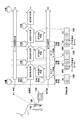
- FIG. 5 is a diagram showing an example in which the body fluid component measurement system 100 according to the present embodiment is used by such a usage method. As shown in FIG. 5, in the body fluid component measurement system 100, there are three processing states (initial processing state, monitoring processing state, and replacement processing state).
- the transmission unit A starts a blood glucose level monitoring process.
- measurement by the sensor unit 110 is executed based on an instruction from the CPU 222 based on a program for calculating the concentration of the body fluid component stored in the memory 128 in the transmission unit A.
- the blood glucose level data calculated based on the measurement data and stored in the IC tag 221 is transmitted to the display unit 130 by the transmission unit A based on an instruction from the CPU 232 in the display unit 130, thereby displaying the display unit. 130. Details of the monitoring process will be described later.
- transmission unit B another transmission unit 120 (hereinafter, transmission unit B) is charged by the charging device 300 ([a]).
- transmission unit B another transmission unit 120
- the subject replaces the transmitting unit B that has been charged. Details of the exchange process will be described later.
- the user attaches the transmission unit A to the charging device 300 before taking out the transmission unit B from the charging device 300, and the charging device 300 has two transmission units 120 (transmission unit A). And the transmitter B) are simultaneously mounted ([b]). In this state, data including identification information for communication is transferred from the transmission unit A to the transmission unit B. Thereafter, the transmission unit B is taken out from the charging device 300 and attached to the sensor unit 110, and the secondary battery 224 of the transmission unit A is charged. Data takeover processing in the charging device 300 will be described later.
- the transmission unit B starts the blood sugar level monitoring process To do.
- measurement by the sensor unit 110 is performed based on an instruction from the CPU 222 in the transmission unit B.
- the blood glucose level data calculated based on the measurement data and stored in the IC tag 221 is transmitted to the display unit 130 by the transmission unit B based on an instruction from the CPU 232 in the display unit 130, thereby displaying the display unit. 130.
- the transmission part 120A is connected to the charging device 300 and charged ([c]).
- the subject exchanges with the transmission unit A that has been fully charged.
- the state of the charging device 300 at this time is shown in [d] and [e].
- data transfer from the transmission unit B to the transmission unit A is performed.
- the transmission unit A is taken out from the charging device 300 and attached to the sensor unit 110, and the secondary battery 224 of the transmission unit B is charged by the charging device 300.
- the monitoring process is continued while the exchange of the transmission unit A and the transmission unit B is repeated until the sensor unit 110 is replaced.
- the measurement in the sensor unit 110 is executed based on an instruction from the CPU 222 based on a program for calculating the concentration of the body fluid component stored in the memory 128 in the transmission unit 120. Since the blood glucose level data calculated in the transmission unit 120 based on the measurement data from the sensor unit 110 is stored in the IC tag 221, the display unit 130 can always operate near the transmission unit 120 during the monitoring process. It is not necessary to be mounted on. That is, even when the power of the display unit 130 is turned off, the monitoring process is not interrupted. For this reason, one display unit 130 is sufficient.
- the sensor unit 110 When it is time to replace the sensor unit 110, the sensor unit 110 is replaced, and a new sensor unit 110 is placed on the subject's skin. In this case, the transmission unit A or the transmission unit B and the display unit 130 continue to use what has been used so far, but since the sensor unit 110 has been replaced, initial processing is executed again.
- the transmission unit 120 is reduced in weight and size, and monitoring processing is interrupted. It is possible to shorten the time.
- the transmission unit 120 is replaced with another transmission unit 120 each time the remaining amount of the secondary battery 224 decreases.
- the processes executed in the initial process (information input process necessary for calculating calibration information, information setting process necessary for establishing communication between the transmission unit and the display unit, etc.) are performed again. It is inconvenient for the subject to execute.
- the workload is high for the subject.
- the charging device 300 has the following functions.
- the communication identification information is set.
- the IC tag 221 is provided in the transmission unit 120 in order to realize the above function under the above usage method, and the next transmission unit 120 is replaced when the transmission unit 120 is replaced.
- Various types of information to be passed on to the IC tag 221 are stored.
- a specific processing flow for realizing the above function in each processing (initial processing, monitoring processing, replacement processing, charging processing) shown in FIG. 5 will be described.
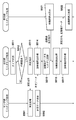
- FIG. 6 is a flowchart showing a flow of initial processing of each part in the body fluid component measurement system 100 according to the present embodiment.
- the sensor unit 110 is placed in the subject in step S401, the transmission unit 120 is attached to the sensor unit 110 in step S411, and the display unit 130 is Communication identification information (communication ID) necessary for communication between the transmission unit 120 and the display unit 130 is input.
- the subject turns on the power of the transmission unit 120 and activates the transmission unit 120.
- step S413 Since the communication identification information is not stored in the IC tag 221 of the transmission unit 120 at the time of step S413, which is the initial process, the transmission unit 120 reads the default communication identification information held in the memory 128. Then, establishment of wireless communication with the display unit 130 is attempted using the read communication identification information (steps S414 and S422). Specifically, the transmission unit 120 and the display unit 130 mutually confirm the identification information for communication, and if they match, the wireless communication is started. On the other hand, if they do not match, wireless communication is not performed. If communication is not established, an error message indicating that the communication has not been established may be output.
- the display unit 130 may display a list of communication identification information of the transmission unit 120 that can establish communication, and allow the user to select the communication identification information (in this case, the communication identification information in S421). Input operation is not required).
- the transmission unit 120 establishes wireless communication with the display unit 130 in this way, it records the communication identification information used for the wireless communication in the IC tag 221 (step S415).
- the communication identification information recorded in the IC tag 221 is taken over by another (charged) transmission unit 120 when the transmission unit 120 is charged in the charging device 300.
- step S423 a measurement result measured in advance in the SMBG machine is received.
- the display unit 130 that has received the measurement result measured in advance in the SMBG machine proceeds to step S424, and transmits the received SMBG measurement result to the transmission unit 120.
- the process proceeds to step S416, and instructs the sensor unit 110 to perform a sampling process for generating calibration information.
- the sensor unit 110 executes the measurement process in step S402 and transmits the measurement data to the transmission unit 120 in step S403.
- the measurement data recorded on the IC tag 117 is read by the IC tag transmission / reception module 122 of the transmission unit 122.
- step S417 the transmission unit 120 that has received the measurement data from the sensor unit 110 calculates calibration information from the received measurement data and the SMBG measurement result. Further, the process proceeds to step S418, and the transmission unit 120 records the calculated calibration information in the IC tag 221. Thereby, since the calibration information is included in the data handed over to the other transmission unit 120, it is not necessary to recalculate the calibration information when the transmission unit 120 is replaced.
- FIG. 7 is a flowchart showing a monitoring process flow of the body fluid component measurement system 100 according to the present embodiment.
- step S511 timer measurement is started, and in step S512, the CPU 222 in the transmission unit 120 determines whether or not a predetermined time has elapsed. If it is determined in step S512 that the predetermined time has elapsed, the process advances to step S513, and the transmission unit 120 instructs the sensor unit 110 to perform measurement. As a result, measurement instructions are transmitted from the transmission unit 120 to the sensor unit 110 at predetermined time intervals.
- the sensor unit 110 that has received the measurement instruction from the sensor unit 110 executes a measurement process in step S501. Further, in step S502, the measurement data obtained as a result of the measurement process is transmitted to the transmission unit 120. In the present embodiment, the measurement data recorded on the IC tag 117 is read by the IC tag transmission / reception module 122 of the transmission unit 120. In step S514, the transmission unit 120 that has received the measurement data from the sensor unit 110 calculates blood glucose level data based on the received measurement data and the calibration information stored in the IC tag 221. Further, in step S515, the calculated blood glucose level data is recorded on the IC tag 221 in association with the current date and time (measurement date and time).
- the measurement data recorded on the IC tag 221 is measurement data for a predetermined number of times determined according to the memory capacity of the IC tag 221.
- the CPU 222 controls recording of the measurement data on the IC tag 221 so that the latest measurement data for a predetermined number of times is held.
- the communication identification information and the calibration information obtained in the initial process are recorded in the IC tag 221 so that the data recorded in the IC tag 221 in the charging device 300 is transferred to another transmission unit. To do. By doing in this way, even if the transmission unit 120 is replaced, the communication identification information and the calibration information used for the wireless communication and blood glucose level calculation processing in the transmission unit 120 before replacement are taken over as they are. Is possible. In addition, since the measurement date and time and the measurement data are recorded in the IC tag 221, the measurement data that has not been transmitted to the display unit 130 can be prevented from being lost due to the exchange of the transmission unit 120.
- step S521 when the display unit 130 receives a blood glucose level display instruction from the subject, the display unit 130 transmits the blood glucose level display instruction to the transmission unit 120.
- step S516 the transmission unit 120 that has received the blood glucose level display instruction reads the blood glucose level that has not been transmitted to the display unit 130 and the measurement date and time from the IC tag 221.
- step S517 the transmission unit 120 is transmitted to the display unit 130 by the transmission unit 120.
- the blood glucose level data and measurement date and time transmitted by the transmission unit 120 are displayed on the display unit 130 in step S522.
- FIG. 8 is a flowchart showing the flow of the replacement process of the body fluid component measurement system 100 according to the present embodiment.
- step S611 a new transmission unit 120 is attached to the sensor unit 110.
- step S612 the subject turns on the new transmission unit 120 and activates the transmission unit 120.
- the process proceeds to step S613.
- step S613, the transmission unit 120 reads the communication identification information stored in the IC tag 221.
- steps S614 and S621 the transmission unit 120 establishes wireless communication with the display unit 130 using the communication identification information. Try. If the communication identification information is not recorded in the IC tag 221 at this time, the transmission unit 120 executes the initial processing described above with reference to FIG.
- the display unit 130 compares the communication identification information used when communicating with the transmission unit 120 before the exchange and the communication identification information read from the sensor unit 110 by the transmission unit 120 after the exchange. If they match, wireless communication is established. On the other hand, if they do not match, wireless communication is not established.
- the data of the IC tag 221 is written in the IC tag 221 of another transmission unit 120 in the charging device 300. Therefore, by recording the communication identification information between the transmission unit 120 and the display unit 130 on the IC tag 221, the communication identification information can be taken over even when the transmission unit 120 is exchanged. Become. Thereby, it is possible to reduce the work load on the subject when the transmission unit 120 is replaced, and it is possible to shorten the replacement time when the transmission unit 120 is replaced. That is, it is possible to shorten the time during which the continuous monitoring of the blood sugar level is interrupted.
- FIG. 9 is a flowchart for explaining the operation of the charging apparatus 300.
- the transmission unit 120 is newly attached to the first charging port 300a for charging will be described.
- the operation when the transmission unit 120 is newly attached to the second charging port 300b is replaced with the second and first charging ports in the operations described below, respectively. Processing.
- the following steps are realized mainly by the controller 310 executing a program stored in a memory (not shown).
- step S801 the determination unit 313 of the charging apparatus 300 determines whether or not the transmission unit 120 is newly attached at the first and second charging ports. Here, it is determined that the transmission unit 120 is attached when the charging port in the empty state is switched to the attached state.
- the mounting state can be detected by, for example, monitoring the operating state of the power supply units 302a and 302b. If a new attachment of the transmission unit 120 has not been detected, this process ends. If new attachment of the transmission unit 120 to the first charging port 300a is detected, the process proceeds to step S802.
- step S802 the acquisition unit 311 acquires data for transmission from the IC tag 221 of the transmission unit 120 using the IC tag transmission / reception module 301a of the first charging port 300a to which the transmission unit 120 is newly attached. Is held in the buffer 312.
- the acquired data includes, for example, communication identification information, calibration information, blood glucose level data, measurement date and time, and the like.
- step S803 the determination unit 313 determines whether another transmission unit 120 is already mounted on the second charging port 300b that is the charging port that is not the charging port to which the transmission unit 120 is newly mounted. Determine whether. If the second charging port is empty, this process ends. If another transmitter 120 is attached to the second charging port, the process proceeds to step S804.
- step S804 the transmission unit 314 transmits (writes) the data held in the buffer 312 in step S802 to the IC tag 221 of the transmission unit 120 attached to the second charging port using the IC tag transmission / reception module 301b. ).
- step S805 the controller 310 turns on the lamp 322b in the second charging port to notify the completion of data transfer. The user can recognize that the data transfer has been completed by confirming that the lamp is turned on, and can take over the data reliably by taking out the transmitter 120 from the charging port after the lamp is turned on.
- the charging device 300 operates as described above, so that the data of the transmission unit 120 newly attached to one charging port is transferred to the transmission unit 120 already attached to the other charging port.
- the charging device 300 is provided with initialization switches 321a and 321b at each charging port, and the controller 310 has the IC tag 221 of the transmission unit 120 attached to the charging port where the initialization switches 321a and 321b are operated. Clear the recorded contents of.
- the transmission unit 120 in which the contents of the IC tag 221 are cleared is attached to the sensor unit 110, the above-described initial processing is performed.
- the execution conditions used by the determination unit 313 are not limited to those described above. For example, it may be added to the execution condition that the charging state of the transmission unit 120 that is the data takeover destination is the charging completion. Furthermore, if the time information such as the measurement date / time is included in the data to be inherited, the execution condition is that the latest time information is newer than the latest time information recorded in the transmission unit 120 that is the data takeover destination. May be added.
- the data of the newly installed transmission unit 120 is taken over by the already installed transmission unit 120, and the two transmission units have the same data.
- the present invention is not limited to this.
- the data of the IC tag 221 of the newly installed transmitter 120 may be deleted after the data transfer is completed.
- data may be exchanged between the newly installed transmitter 120 and the already installed transmitter 120.
- the secondary unit mounted on the transmission unit 120 in order to reduce the size and size of the transmission unit 120 and improve the convenience of the subject. It was set as the structure which suppresses the capacity
- various information that should be taken over with the replacement of the transmission unit 120 is transferred to the transmission unit 120 at the replacement destination in the charging device 300. It was set as the structure which can be taken over. For example, if calibration information is included in the information to be taken over, the calibration information set when the sensor unit 110 is detained will be taken over even when the transmission unit 120 is replaced. This eliminates the need to re-enter information necessary for calculating the calibration information.
- the blood glucose level data calculated in the transmission unit 120 before the exchange is inherited even when the transmission unit 120 is exchanged.
- the blood glucose level data before the replacement can be read and displayed on the display unit 130 by the same operation as before the replacement.
- the identification information for communication is included in the information to be inherited, the identification information for communication between the transmission unit 120 and the display unit 130 will be inherited even when the transmission unit 120 is exchanged. When the unit 120 is replaced, there is no need to set communication identification information again.
- the information to be taken over may include information other than the information described above, or may be one of the information described above.
- the communication method between the transmission unit 120 and the display unit 130 is not particularly mentioned.
- the communication method between the transmission unit 120 and the display unit 130 is the same as that in the first embodiment.
- the present invention is not limited to this.
- various known communication methods such as a method using electromagnetic induction, human body communication, and proximity or proximity non-contact communication are used. be able to.
- the sensor part 110 and the transmission part 120 were set as the structure which performs a near field communication using an IC tag, it is not limited to this, A contact point, such as a metal, is used, and a transmission part The sensor unit may be electrically connected.
- the two transmission units 120 are used.
- the present invention is not limited to this and may be three or more.
- the charging device also has three or more charging ports, and when the transmission unit 120 is newly attached to the charging port, the data recorded in the IC tag 221 of the newly attached transmission unit 120 is This is taken over by a plurality of other transmission units 120 attached to the charging device 300.
- the blood glucose level data is transmitted from the transmission unit 120 to the display unit 130 only when there is a blood glucose level display instruction from the display unit 130.
- the present invention is not limited to this, and each time the blood glucose level data is calculated in the transmission unit 120, the transmission to the display unit 130 may be performed in parallel with the writing to the IC tag 221.
- charging device 300 there may be a plurality of pairs of charging ports that take over data. By doing so, a plurality of users can share one charging device 300.
- the charging mechanism in the charging port is configured to connect the transmission unit 120 to the charging connector, a configuration for charging in a non-contact manner may be used.
- the charging device 300 acquired the data recorded on the IC tag in order to acquire data from the transmission unit 120 by the proximity wireless communication, the present invention is not limited to this.
- a signal line may be included in the charging connector, and the charging device 300 may acquire data from the transmission unit 120 by wire.
- the charging device 300 having the function of charging the transmission unit 120 is shown as the device that places a plurality of transmission units 120 and transfers data.
- the present invention is not limited to this.
- a data transfer device may be used only for data transfer, that is, the charging device 300 may be omitted from the charging function.
- the communication between the transmission unit 120 and the display unit 130 which is an external device is wireless communication, the communication is not limited to this and may be wired communication.
Landscapes
- Health & Medical Sciences (AREA)
- Life Sciences & Earth Sciences (AREA)
- Physics & Mathematics (AREA)
- Engineering & Computer Science (AREA)
- Veterinary Medicine (AREA)
- General Health & Medical Sciences (AREA)
- Pathology (AREA)
- Biomedical Technology (AREA)
- Heart & Thoracic Surgery (AREA)
- Medical Informatics (AREA)
- Molecular Biology (AREA)
- Surgery (AREA)
- Animal Behavior & Ethology (AREA)
- Public Health (AREA)
- Biophysics (AREA)
- Optics & Photonics (AREA)
- Computer Networks & Wireless Communication (AREA)
- Hematology (AREA)
- Emergency Medicine (AREA)
- Spectroscopy & Molecular Physics (AREA)
- Measurement Of The Respiration, Hearing Ability, Form, And Blood Characteristics Of Living Organisms (AREA)
Abstract
L'invention concerne un dispositif sur lequel des dispositifs de transmission sont chargés ; le dispositif de transmission est installé de façon détachable sur un dispositif de capteur, qui est implanté dans une personne examinée pour acquérir un biosignal provenant de ladite personne examinée, et ledit dispositif de transmission acquiert des bioinformations provenant du biosignal acquis par le dispositif de capteur et les transmet à un dispositif externe. Le dispositif comprend : un premier et un second port sur lesquels les dispositifs de transmission sont montés et chargés ; et des unités de communication respectives, qui sont disposées sur lesdits ports et communiquent avec les dispositifs de transmission montés sur les ports respectifs. Lorsqu'un dispositif de transmission est nouvellement monté sur l'un des ports, le dispositif acquiert les données à transmettre comprenant des informations d'identification de communication pour ladite transmission à partir du dispositif de transmission nouvellement monté à l'aide de l'unité de communication dudit port, et transmet lesdites données de transmission acquises à l'autre dispositif de transmission qui est déjà monté sur l'autre port à l'aide de l'unité de communication disposée sur ledit autre port.
Priority Applications (1)
| Application Number | Priority Date | Filing Date | Title |
|---|---|---|---|
| US14/037,623 US9498127B2 (en) | 2011-03-29 | 2013-09-26 | Data transfer device and data transfer system |
Applications Claiming Priority (2)
| Application Number | Priority Date | Filing Date | Title |
|---|---|---|---|
| JP2011-071315 | 2011-03-29 | ||
| JP2011071315 | 2011-03-29 |
Related Child Applications (1)
| Application Number | Title | Priority Date | Filing Date |
|---|---|---|---|
| US14/037,623 Continuation US9498127B2 (en) | 2011-03-29 | 2013-09-26 | Data transfer device and data transfer system |
Publications (1)
| Publication Number | Publication Date |
|---|---|
| WO2012131828A1 true WO2012131828A1 (fr) | 2012-10-04 |
Family
ID=46929671
Family Applications (1)
| Application Number | Title | Priority Date | Filing Date |
|---|---|---|---|
| PCT/JP2011/006948 Ceased WO2012131828A1 (fr) | 2011-03-29 | 2011-12-13 | Dispositif de transfert de données et système de transfert de données |
Country Status (2)
| Country | Link |
|---|---|
| US (1) | US9498127B2 (fr) |
| WO (1) | WO2012131828A1 (fr) |
Cited By (1)
| Publication number | Priority date | Publication date | Assignee | Title |
|---|---|---|---|---|
| JP2021119734A (ja) * | 2020-01-14 | 2021-08-12 | 華廣生技股▲ふん▼有限公司Bionime Corporation | 生理信号送信機用の充電装置及びその充電方法 |
Families Citing this family (1)
| Publication number | Priority date | Publication date | Assignee | Title |
|---|---|---|---|---|
| WO2025106281A1 (fr) * | 2023-11-13 | 2025-05-22 | Abbott Diabetes Care Inc. | Système sans fil de surveillance de glucose à patch émetteur remplaçable |
Citations (2)
| Publication number | Priority date | Publication date | Assignee | Title |
|---|---|---|---|---|
| JP2002526137A (ja) * | 1998-10-08 | 2002-08-20 | メドトロニック ミニメド インコーポレイテッド | 遠隔形質モニタシステム |
| JP2008246204A (ja) * | 2007-03-20 | 2008-10-16 | F Hoffmann-La Roche Ag | 検体濃度をインビボで測定するシステム |
Family Cites Families (15)
| Publication number | Priority date | Publication date | Assignee | Title |
|---|---|---|---|---|
| US6572542B1 (en) * | 2000-03-03 | 2003-06-03 | Medtronic, Inc. | System and method for monitoring and controlling the glycemic state of a patient |
| US7044911B2 (en) * | 2001-06-29 | 2006-05-16 | Philometron, Inc. | Gateway platform for biological monitoring and delivery of therapeutic compounds |
| US7468033B2 (en) * | 2004-09-08 | 2008-12-23 | Medtronic Minimed, Inc. | Blood contacting sensor |
| US7801582B2 (en) * | 2006-03-31 | 2010-09-21 | Abbott Diabetes Care Inc. | Analyte monitoring and management system and methods therefor |
| US20100262117A1 (en) * | 2007-11-02 | 2010-10-14 | University Of Virginia Patent Foundation | Predictive control based system and method for control of insulin delivery in diabetes using glucose sensing |
| JP5043810B2 (ja) * | 2007-12-26 | 2012-10-10 | パナソニック株式会社 | 生体試料測定装置およびこれを備えた生体試料測定システム |
| US8145267B2 (en) * | 2008-01-10 | 2012-03-27 | Panasonic Corporation | Biological sample measurement apparatus |
| US8591455B2 (en) * | 2008-02-21 | 2013-11-26 | Dexcom, Inc. | Systems and methods for customizing delivery of sensor data |
| JP4891283B2 (ja) | 2008-03-24 | 2012-03-07 | 日本電信電話株式会社 | 酸化性ガスの測定方法および測定装置 |
| US20110160555A1 (en) * | 2008-07-31 | 2011-06-30 | Jacques Reifman | Universal Models for Predicting Glucose Concentration in Humans |
| EP3315958B1 (fr) * | 2008-11-04 | 2021-09-15 | PHC Holdings Corporation | Dispositif de mesure |
| JP2011212117A (ja) * | 2010-03-31 | 2011-10-27 | Terumo Corp | 体液成分測定システム |
| JPWO2012127870A1 (ja) * | 2011-03-23 | 2014-07-24 | パナソニックヘルスケア株式会社 | 生体情報測定装置 |
| JP5837570B2 (ja) * | 2011-03-25 | 2015-12-24 | テルモ株式会社 | 体液成分測定システム |
| US8622901B2 (en) * | 2011-05-13 | 2014-01-07 | Fujitsu Limited | Continuous monitoring of stress using accelerometer data |
-
2011
- 2011-12-13 WO PCT/JP2011/006948 patent/WO2012131828A1/fr not_active Ceased
-
2013
- 2013-09-26 US US14/037,623 patent/US9498127B2/en active Active
Patent Citations (2)
| Publication number | Priority date | Publication date | Assignee | Title |
|---|---|---|---|---|
| JP2002526137A (ja) * | 1998-10-08 | 2002-08-20 | メドトロニック ミニメド インコーポレイテッド | 遠隔形質モニタシステム |
| JP2008246204A (ja) * | 2007-03-20 | 2008-10-16 | F Hoffmann-La Roche Ag | 検体濃度をインビボで測定するシステム |
Cited By (2)
| Publication number | Priority date | Publication date | Assignee | Title |
|---|---|---|---|---|
| JP2021119734A (ja) * | 2020-01-14 | 2021-08-12 | 華廣生技股▲ふん▼有限公司Bionime Corporation | 生理信号送信機用の充電装置及びその充電方法 |
| JP7209023B2 (ja) | 2020-01-14 | 2023-01-19 | 華廣生技股▲ふん▼有限公司 | 生理信号送信機用の充電装置及びその充電方法 |
Also Published As
| Publication number | Publication date |
|---|---|
| US9498127B2 (en) | 2016-11-22 |
| US20140058222A1 (en) | 2014-02-27 |
Similar Documents
| Publication | Publication Date | Title |
|---|---|---|
| JP5837570B2 (ja) | 体液成分測定システム | |
| Mortellaro et al. | Performance characterization of an abiotic and fluorescent-based continuous glucose monitoring system in patients with type 1 diabetes | |
| RU2707819C2 (ru) | Набор для определения концентрации аналита | |
| EP3138488B1 (fr) | Module de détection et kit de détermination d'une concentration d'analyte | |
| EP2554116A1 (fr) | Système de mesure de composants de fluide organique | |
| CA2669294C (fr) | Appareil de detection d'analyte destine a etre utilise dans les hopitaux | |
| RU2539366C2 (ru) | Устройство для непрерывного анализа и система регулирования компонента образца | |
| EP3207871B1 (fr) | Appareil de collecte de glucose en continu | |
| JPWO2009099148A1 (ja) | コード読み取り装置およびこれを用いたデータ収集システム | |
| CN108366740B (zh) | 测量多个生物信息的便携式复合传感器装置及测量方法 | |
| US20120319864A1 (en) | Bodily fluid component measurement system | |
| US9498127B2 (en) | Data transfer device and data transfer system | |
| EP3982832A1 (fr) | Couplage mécanique d'un capteur sélectif d'analyte et d'un système de perfusion | |
| KR102255447B1 (ko) | 복합 생체신호 측정을 위한 멀티센서 기반 유연 패치 장치 및 이를 이용한 복합 생체신호 측정방법 | |
| CA3213600A1 (fr) | Systeme de surveillance d'analyte augmente | |
| US20200138345A1 (en) | Environmental detection and/or temperature compensation in an analyte monitoring system | |
| US20240285849A1 (en) | Combined sensor and infusion system | |
| CA3161009C (fr) | Procedes et systemes pour reduire la difference entre des taux d'analyte calcules et mesures | |
| JP7121624B2 (ja) | グルコース測定モジュール及びグルコース測定システム | |
| CA3161009A1 (fr) | Procedes et systemes pour reduire la difference entre des taux d'analyte calcules et mesures | |
| HK1258925B (zh) | 用於确定分析物浓度的套件 | |
| JP2007117435A (ja) | 生体情報収集装置 |
Legal Events
| Date | Code | Title | Description |
|---|---|---|---|
| 121 | Ep: the epo has been informed by wipo that ep was designated in this application |
Ref document number: 11862658 Country of ref document: EP Kind code of ref document: A1 |
|
| NENP | Non-entry into the national phase |
Ref country code: DE |
|
| 122 | Ep: pct application non-entry in european phase |
Ref document number: 11862658 Country of ref document: EP Kind code of ref document: A1 |
|
| NENP | Non-entry into the national phase |
Ref country code: JP |