WO2012131895A1 - Dispositif, procédé et programme de codage d'image, et dispositif, procédé et programme de décodage d'image - Google Patents
Dispositif, procédé et programme de codage d'image, et dispositif, procédé et programme de décodage d'image Download PDFInfo
- Publication number
- WO2012131895A1 WO2012131895A1 PCT/JP2011/057782 JP2011057782W WO2012131895A1 WO 2012131895 A1 WO2012131895 A1 WO 2012131895A1 JP 2011057782 W JP2011057782 W JP 2011057782W WO 2012131895 A1 WO2012131895 A1 WO 2012131895A1
- Authority
- WO
- WIPO (PCT)
- Prior art keywords
- image
- information
- parallax
- filter
- unit
- Prior art date
- Legal status (The legal status is an assumption and is not a legal conclusion. Google has not performed a legal analysis and makes no representation as to the accuracy of the status listed.)
- Ceased
Links
Images



Classifications
-
- G—PHYSICS
- G06—COMPUTING OR CALCULATING; COUNTING
- G06V—IMAGE OR VIDEO RECOGNITION OR UNDERSTANDING
- G06V20/00—Scenes; Scene-specific elements
- G06V20/60—Type of objects
- G06V20/64—Three-dimensional [3D] objects
-
- H—ELECTRICITY
- H04—ELECTRIC COMMUNICATION TECHNIQUE
- H04N—PICTORIAL COMMUNICATION, e.g. TELEVISION
- H04N19/00—Methods or arrangements for coding, decoding, compressing or decompressing digital video signals
- H04N19/50—Methods or arrangements for coding, decoding, compressing or decompressing digital video signals using predictive coding
- H04N19/597—Methods or arrangements for coding, decoding, compressing or decompressing digital video signals using predictive coding specially adapted for multi-view video sequence encoding
-
- H—ELECTRICITY
- H04—ELECTRIC COMMUNICATION TECHNIQUE
- H04N—PICTORIAL COMMUNICATION, e.g. TELEVISION
- H04N13/00—Stereoscopic video systems; Multi-view video systems; Details thereof
- H04N13/10—Processing, recording or transmission of stereoscopic or multi-view image signals
- H04N13/106—Processing image signals
- H04N13/111—Transformation of image signals corresponding to virtual viewpoints, e.g. spatial image interpolation
-
- H—ELECTRICITY
- H04—ELECTRIC COMMUNICATION TECHNIQUE
- H04N—PICTORIAL COMMUNICATION, e.g. TELEVISION
- H04N19/00—Methods or arrangements for coding, decoding, compressing or decompressing digital video signals
- H04N19/80—Details of filtering operations specially adapted for video compression, e.g. for pixel interpolation
- H04N19/82—Details of filtering operations specially adapted for video compression, e.g. for pixel interpolation involving filtering within a prediction loop
-
- H—ELECTRICITY
- H04—ELECTRIC COMMUNICATION TECHNIQUE
- H04N—PICTORIAL COMMUNICATION, e.g. TELEVISION
- H04N13/00—Stereoscopic video systems; Multi-view video systems; Details thereof
- H04N13/10—Processing, recording or transmission of stereoscopic or multi-view image signals
- H04N13/106—Processing image signals
- H04N13/161—Encoding, multiplexing or demultiplexing different image signal components
Definitions
- Embodiments described herein relate generally to an image encoding device, a method, and a program, and an image decoding device, a method, and a program.
- a parallax image of a viewpoint to be encoded is generated from a locally decoded image of a viewpoint different from the viewpoint of the encoding target by an image synthesis technique, and the synthesized parallax image of the viewpoint is left as it is. It is used as a decoded image or a predicted image at the time of encoding.
- the image encoding device of the embodiment includes an image synthesis unit, a first filter processing unit, a predicted image generation unit, and an encoding unit.
- the image composition unit generates the first parallax image of the viewpoint in the encoding target image using at least one of the depth information and the parallax information in the second parallax image of another viewpoint different from the viewpoint.
- the first filter processing unit performs a filter process on the generated first parallax image based on the first filter information.
- the predicted image generation unit generates a predicted image using the first parallax image after the filter processing as a reference image.
- the encoding unit generates encoded data from the input image and the predicted image.
- FIG. 1 is a diagram of an image encoding device according to Embodiment 1.
- FIG. FIG. 4 is a diagram illustrating an example of encoding according to the first embodiment.
- FIG. 4 is a diagram illustrating an example of camera parameters according to the first embodiment.
- 5 is a flowchart of encoding processing according to the first embodiment.
- FIG. 10 is a flowchart of decoding processing according to the second embodiment.
- FIG. FIG. 11 is a diagram illustrating an example of encoding a multi-parallax image according to the third embodiment.
- a parallax image at a viewpoint to be encoded is generated from a decoded parallax image at a viewpoint different from the viewpoint to be encoded by an image synthesis technique, and the synthesized parallax image at the viewpoint is encoded. It is an image coding apparatus used for the prediction image in the case of.
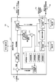
- FIG. 1 is a block diagram showing a functional configuration of the image coding apparatus according to the first embodiment.
- the image encoding device 100 includes an encoding control unit 116, an image encoding unit 117, a prefilter design unit 108, and a post filter design unit 107.
- the encoding control unit 116 controls the entire image encoding unit 117.
- the prefilter design unit 108 generates filter information used by a prefilter processing unit 110 described later
- the postfilter design unit 107 generates filter information used by a postfilter processing unit 106 described later. Details of the pre-filter design unit 108, the post-filter design unit 107, and the filter information will be described later.
- the image encoding unit 117 receives an input image that is an encoding target image, and combines the parallax image at the encoding target viewpoint from the decoded parallax image at a viewpoint different from the encoding target viewpoint. Is generated, encoded, and output as encoded data S (v) 104.
- the image encoding unit 117 includes a subtractor 111, a transform / quantization unit 115, a variable length encoding unit 118, an inverse transform / inverse quantization unit 114, an adder 113, A prediction image generation unit 112, a prefilter processing unit 110 as a second filter processing unit, an image synthesis unit 109, a post filter processing unit 106 as a first filter processing unit, and a reference image buffer 105 are provided.
- the input image signal I (v) 101 is input to the image encoding unit 117.
- the subtractor 111 obtains a difference between the predicted image signal generated by the predicted image generation unit 112 and the input image signal I (v) 101, and generates a residual signal that is the difference.
- the transform / quantization unit 115 orthogonally transforms the residual signal to obtain orthogonal transform coefficients, and quantizes the orthogonal transform coefficients to obtain quantized orthogonal transform coefficient information.
- This quantized orthogonal transform coefficient information is hereinafter referred to as residual information.
- the orthogonal transformation for example, discrete cosine transformation can be used.
- the residual information (quantized orthogonal transform coefficient information) is input to the variable length coding unit 118 and the inverse transform / inverse quantization 114.
- the inverse transform / inverse quantization 114 performs a process opposite to the process of the transform / quantization unit 115 on the residual information. That is, the inverse transform / inverse quantization 114 performs a process of inverse quantization and inverse orthogonal transform on the residual information to reproduce a locally decoded signal.
- the adder 113 adds the reproduced local decoded signal and the predicted image signal to generate a decoded image signal. This decoded image signal is stored in the reference image buffer 105 as a reference image.
- the reference image buffer 105 is a storage medium such as a frame memory.
- the above-described decoded image signal is stored as reference images 1 to 3 and the like, and, as will be described later, a synthesized image (filtered image in the encoding target image) subjected to filter processing by the post filter processing unit 106, as will be described later.
- (Parallax image of viewpoint) is stored as a reference image Vir.
- the reference image Vir is input to the predicted image generation unit 112, and the predicted image generation unit 112 generates a predicted image signal from the reference image.
- the prefilter processing unit 110 decodes a parallax image R (v ′) that has been decoded from another viewpoint that is different from the viewpoint in the encoding target image, and has been decoded corresponding to the viewpoint of the parallax image R (v ′).
- the depth information or the parallax information D (v ′) is input, and the filter information (second filter information) designed by the pre-filter design unit 108 for the information R (v ′) and D (v ′) is input.
- the filter information includes a filter coefficient, applicability of the filter, and the number of pixels used for the filter.
- the pre-filter processing unit 110 performs filtering on the decoded parallax image R (v ′) and the decoded depth information or parallax information D (v ′) corresponding to the viewpoint of the parallax image. Filter processing is performed using the filter coefficient of information and the number of pixels used for the filter. In addition, the prefilter processing unit 110 sends the filter information to the variable length coding unit 118.
- the image synthesis unit 109 converts the viewpoint parallax image in the encoding target image into a decoded parallax image of another viewpoint different from the viewpoint and decoded depth information or parallax information corresponding to the viewpoint of the parallax image. Generated from the filtered information.
- the viewpoint parallax image in the generated encoding target image is referred to as a composite image.
- FIG. 2 is a diagram for explaining an example of encoding.
- the image synthesis unit 109 corresponds to the parallax image R (0) of the other viewpoint 0 and the corresponding viewpoint.
- the parallax image corresponding to the viewpoint 2 of the encoding target image is generated by 3D Warping from the depth information and the parallax information D (0).
- the image synthesis unit 109 synthesizes the (X i , Y i ) block of the synthesized image at the viewpoint i of the encoding target image from the (X j , Y j ) block of the parallax image of the viewpoint j used for image synthesis. .
- (X j , Y j ) is calculated by the following equations (1) and (2).
- R represents the camera rotation matrix
- A represents the internal camera matrix
- T represents the parallel progression of the cameras.
- Z indicates a depth value.
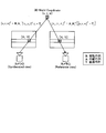
- FIG. 3 is an explanatory diagram showing an example of image composition.
- the parallax image of the view j from the camera C j [X j, Y j] from the synthesized image [X i, Y i] viewpoint i from the camera C i indicates that is generated Yes.
- [X j , Y j ] is calculated using equations (1) and (2).
- the parallax images R (0), R (2) and the corresponding depth information, parallax information D (0), D A composite image can be generated using the information on the two viewpoints of 2).
- the composite image generated using R (0), D (0), and R (2), D Both of the composite images generated using (2) may be used as reference images, or an image obtained by taking a weighted average of two composite images may be used as a composite image.
- the composite image generated by 3D Warping may have a region (Hole) that cannot be composed due to a hidden surface region or the like.
- the image composition unit 109 performs processing for filling the Hole with the pixel value of a distant area (background area) adjacent to the Hole using the depth information. Also good.
- the Hole is left as it is, and the variable length encoding unit 118 uses which pixel value to fill the Hole as the filter information used in the post filter processing unit 106.
- the information for designating may be encoded.
- a method may be adopted in which pixels corresponding to Hole are sequentially scanned, and information regarding Hole is added by Differential Pulse Code Modulation (DPCM).
- DPCM Differential Pulse Code Modulation
- H As in the intra-screen prediction in H.264, a method of designating the direction in which Hole is filled may be used. In this case, on the decoding side, the hidden surface area can be filled in accordance with the information of the filter filling the Hole encoded here.
- the post filter processing unit 106 performs post filter processing on the composite image using the filter information (first filter information) designed by the post filter design unit 107.
- the filter information (second filter information) generated by the post filter design unit 107 includes a filter coefficient, applicability of the filter, and the number of pixels used for the filter.
- the post filter processing unit 106 performs filter processing on the composite image using the filter coefficient of the filter information and the number of pixels used for the filter. Further, the post filter processing unit 106 sends the filter information to the variable length coding unit 118, and stores the composite image on which the filter processing has been performed in the reference image buffer 105 as a reference image Vir.
- the variable length encoding unit 118 generates encoded data S (v) 104 by variable length encoding the residual information output from the transform / quantization unit 115 and the prediction mode information output from the prediction signal generation unit 112. To do. Further, the variable length encoding unit 118 performs variable length encoding processing on the filter information output from the prefilter processing unit 110 and the post filter processing unit 106, and adds the encoded filter information to the encoded data. . That is, the variable length encoding unit 118 generates encoded data S (v) 104 including the encoded residual information and the encoded filter information. Then, the variable length encoding unit 118 outputs the encoded data S (v) 104.
- the encoded data S (v) 104 is input to the image decoding apparatus via a network or a storage medium.
- H As in the Skip mode in H.264, when a synthesized image obtained by applying the filtering process by the post-filter processing unit 106 to the synthesized image generated by the image synthesizing unit 109 without encoding the residual information is output as it is, By adding information indicating that encoding of information is omitted to the encoded data 104, the same image can be decoded on the decoding side.
- the post filter design unit 107 designs a post filter.
- the post filter processing unit 106 constructs a Wiener-Hopf equation using the composite image generated by the image composition unit 109 and the input image 101 that is the encoding target image, and obtains a solution, thereby obtaining the input image 101, A filter that minimizes the square error of the combined image after the filter application by the post filter processing unit 106 can be designed.
- Filter information related to the filter designed by the post filter design unit 107 (filter coefficient, applicability of the filter, and number of pixels used for the filter), the post filter processing unit 106, and the variable length coding unit 118.
- the prefilter design unit 108 designs a prefilter.
- the prefilter design unit 108 similarly uses a parallax image of another viewpoint used for image synthesis and depth information corresponding to the viewpoint so as to minimize a square error between the synthesized image and the input image 101 of the encoding target image.
- a filter to be applied to a locally decoded signal of disparity information is designed.
- Filter information (filter coefficients, applicability of the filter, and number of pixels used for the filter) related to the filter designed by the pre-filter design unit 108, the pre-filter processing unit 110, and the variable length coding unit 118.
- filter design method is not limited to the method described in the present embodiment, and any design method can be adopted.
- the expression method of the filter coefficient is not particularly limited.
- one or more filter coefficient sets are prepared in advance, information specifying the filter coefficient set to be actually used is encoded, and the image decoding apparatus side It is possible to adopt a method of transmitting to the image decoding device or a method of encoding all the filter coefficients and transmitting them to the image decoding apparatus side.
- the value of the filter coefficient may be encoded as an integer in accordance with integer arithmetic.
- the filter coefficient may be predicted from the coefficients of neighboring pixels using the spatial correlation of the filter coefficient, and the residual may be encoded.
- a difference from a reference filter coefficient set may be calculated, and the residual may be encoded.
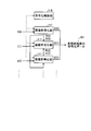
- FIG. 4 is a flowchart illustrating the procedure of the encoding process according to the first embodiment.
- the pre-filter processing unit 110 inputs a decoded parallax image R (v ′) of another viewpoint, decoded depth information or parallax information D (v ′) of the other viewpoint, and inputs these
- the prefilter designed by the prefilter design unit 108 is applied to the information (step S101).
- the image composition unit 109 performs image composition (step S102). That is, the image composition unit 109 uses the decoded viewpoint parallax image R (v ′) of the other viewpoint and the decoded depth information or parallax information D (v ′) of the other viewpoint after the prefilter application. Then, a viewpoint parallax image (composite image) in the encoding target image is generated. Then, the post filter processing unit 106 applies the post filter designed by the post filter design unit 107 to the composite image (step S103), and refers to the composite image to which the post filter is applied as the reference image Vir. Save in the image buffer 105 (step S104).
- the predicted image generation unit 112 acquires the reference image Vir from the reference image buffer 105, and generates a predicted image (step S105). Then, the subtractor 111 performs a subtraction process between the input image 101 that is the encoding target image and the reference image Vir, and outputs a residual signal (step S106). Next, the transform / quantization unit 115 performs orthogonal transform on the residual signal to obtain an orthogonal transform coefficient, quantizes the orthogonal transform coefficient, and obtains residual information that is quantized orthogonal transform coefficient information (step S107).
- variable length coding unit 118 performs variable length coding on the residual information and the filter information input from the pre-filter processing unit 110 and the post-filter processing unit 106 to obtain coded data S (v ) 104 (step S108). Then, the variable length encoding unit 118 outputs the encoded data S (v) 104 (step S109).
- Information or disparity information D (v ′) is generated after applying a pre-filter, and a post-filter is applied to the generated synthesized image as a reference image Vir, and a predicted image is generated from this reference image Vir
- the pre-filter is applied to the decoded depth information or disparity information D (v ′) before the image composition processing by the image composition unit 109, thereby suppressing the occurrence of composition distortion. be able to.
- the synthesized image generated by the image synthesizing unit 109 is synthesized from the parallax images of different viewpoints, the parallax images having different colors may be synthesized and distortion of the synthesized image may increase.
- the error between the original image and the synthesized image becomes large due to the estimation error of the depth information and the influence of the hidden surface.
- the hidden surface cannot be correctly reconstructed in principle by image composition, an error from the original image increases.
- post-filter processing is performed with filter information in order to reduce an error from the viewpoint parallax image, and the filter information is encoded data S ( v)
- the filter information is encoded data S ( v)
- the configuration of the image coding apparatus 100 according to the first embodiment is not limited to the configuration described in the first embodiment.
- only one of the pre-filter processing unit 110 and the post-filter processing unit 106 is used. It is good also as a structure which has. In this case, it is necessary to add only filter information regarding the filter to be used to the encoded data S (v) 104.
- the input image 101 in the image coding apparatus 100 is not limited to only a multi-parallax image signal.
- a multi-parallax parallax image and multi-parallax depth information corresponding to these are provided.
- the depth information / disparity information may be input as the input image 101.
- the second embodiment is an image decoding apparatus that decodes encoded data S (v) 104 transmitted from an image encoding apparatus.
- FIG. 5 is a block diagram illustrating a functional configuration of the image decoding apparatus according to the second embodiment.
- the image decoding apparatus 500 includes a decoding control unit 501 and an image decoding unit 502.
- the decoding control unit 501 controls the entire image decoding unit 502.
- the image decoding unit 502 receives the encoded data S (v) 104 to be decoded from the image coding apparatus according to Embodiment 1 via a network or a storage medium, and the viewpoint parallax in the decoding target image An image is generated from information based on a parallax image of another viewpoint different from the viewpoint.
- the encoded data S (v) 104 to be decoded includes codes of prediction mode information, residual information, and filter information.
- the image decoding unit 502 includes a variable length decoding unit 504, an inverse transform / inverse quantization unit 514, an adder 515, a predicted image generation unit 512, a prefilter processing unit 510, , An image composition unit 509, a post filter processing unit 506, and a reference image buffer 505.
- the variable length decoding unit 504, the inverse transform / inverse quantization unit 514, and the adder 515 function as a decoding unit.
- the variable length decoding unit 504 receives the encoded data S (v) 104, performs variable length decoding processing on the input encoded data S (v) 104, and is included in the encoded data S (v) 104. Prediction mode information, residual information (quantized orthogonal transform coefficient information) and filter information are obtained.
- the variable length decoding unit 504 outputs the decoded residual information to the inverse transform / inverse quantization unit 514, and outputs the decoded filter information to the prefilter processing unit 510 and the post filter processing unit 506. .
- the details of the filter information are the same as those in the first embodiment, and the filter information includes a filter coefficient, applicability of the filter, and the number of pixels used for the filter.
- the inverse transform / inverse quantization unit 514 performs an inverse quantization process and an inverse orthogonal transform process on the residual information and outputs a residual signal.
- the adder 515 adds the residual signal and the predicted image signal generated by the predicted image generation unit 512 to generate a decoded image signal, and outputs the decoded image signal as an output image signal 503.
- the decoded image signal is stored in the reference image buffer 505 as reference images 1 to 3 and the like.
- the reference image buffer 505 is a storage medium such as a frame memory, and stores the decoded image signal as a reference image, and also stores a composite image output from a post filter processing unit 506 described later as a reference image Vir.
- the predicted image generation unit 512 generates a predicted image signal from the reference image stored in the reference image buffer 505.
- the encoded data S (v) 104 includes information indicating that encoding of the residual signal is omitted as in the Skip mode in H.264
- the reference stored in the reference image buffer 505 is stored. By outputting the image as it is, the same image as the image encoding device 100 can be decoded.
- the pre-filter processing unit 510 decodes a parallax image R (v ′) 102 that has been decoded from another viewpoint that is different from the viewpoint in the decoding target image and the viewpoint of the parallax image R (v ′) that has been decoded. Depth information or parallax information D (v ′) 103 is input, and filter information (second filter) sent from the variable-length decoding unit 504 to these pieces of information R (v ′) and D (v ′) is input. Information) is used for prefiltering.
- the details of the filter processing (prefilter processing) by the prefilter processing unit 510 are the same as the processing of the prefilter processing unit 110 of the first embodiment.
- the image synthesis unit 509 converts the viewpoint parallax image in the decoding target image into a decoded parallax image R (v ′) 102 of another viewpoint different from this viewpoint and a decoded depth corresponding to the viewpoint of the parallax image.
- the information or the parallax information D (v ′) 102 is generated from information obtained by performing prefiltering.
- the viewpoint parallax image in the generated decoding target image is referred to as a composite image.
- the details of the composite image generation processing by the composite image unit 509 are the same as the processing by the image composition unit 109 of the first embodiment.
- the post filter processing unit 506 performs post filter processing on the composite image using the filter information (first filter information) sent from the variable length decoding unit 504.
- the post filter processing unit 506 stores the composite image after the filter processing in the reference image buffer 505 as a reference image Vir.
- the reference image Vir is referred to by the predicted image generation unit 512 and used to generate a predicted image.
- FIG. 6 is a flowchart illustrating the procedure of the decryption process according to the second embodiment.
- variable length decoding unit 504 inputs encoded data S (v) 104 to be decoded from the image encoding device 100 via a network or a storage medium (step S201).
- the variable length decoding unit 504 performs variable length decoding processing on the input encoded data S (v) 104 to extract residual information, filter information, and extraction information included in the encoded data S (v) 104.
- Step S202 the variable length decoding unit 504 sends the filter information to the prefilter processing unit 510 and the postfilter processing unit 506 (step S203).
- the decoded residual information is sent to an inverse transform / inverse quantization unit 514, and the inverse transform / inverse quantization unit 514 performs an inverse quantization process and an inverse orthogonal transform process on the residual information to obtain a residual signal. Is output (step S204).
- the prefilter processing unit 510 decodes the parallax image R (v ′) 102 that has been decoded from another viewpoint different from the viewpoint in the decoding target image, and the viewpoint corresponding to the viewpoint of the parallax image R (v ′).
- Depth information or disparity information D (v ′) 103 is input, and the information R (v ′) and D (v ′) is pre-processed using the filter information sent from the variable length decoding unit 504.
- a filter is applied (step S205).
- the image composition unit 509 performs image composition (step S206). That is, the image synthesis unit 509 prefilters the viewpoint parallax image in the decoding target image into the decoded parallax image R (v ′) 102 and the decoded depth information or parallax information D (v ′) 102. It is generated from the processed information and is a composite image.
- the post filter processing unit 506 applies a post filter to the composite image using the filter information sent from the variable length decoding unit 504 (step S207). Then, the post filter processing unit 506 stores the composite image to which the post filter is applied in the reference image buffer 505 as the reference image Vir (step S208).
- the decoded prediction mode information is sent to the prediction image generation unit 512, and the prediction image generation unit 512 acquires the reference image Vir from the reference image buffer 505, and generates a prediction image signal according to the prediction mode information.
- the adder 515 adds the residual signal output from the inverse transform / inverse quantization unit 514 in step S204 and the predicted image signal generated by the predicted image generation unit 512 to obtain a decoded image signal.
- the decoded image signal is generated and output as the output image signal R (v) 503 (step S210).
- Information or disparity information D (v ′) is generated after applying a pre-filter, and a post-filter is applied to the generated synthesized image as a reference image Vir, and a predicted image is generated from this reference image Vir
- a prefilter is applied to the decoded depth information or disparity information D (v ′) before the image composition processing by the image composition unit 509. , The occurrence of synthetic distortion can be suppressed.
- post-filter processing is performed on the filter information in order to reduce an error from the viewpoint parallax image, and this filter information is added to the encoded data S (v) 104. By doing so, distortion caused by image composition can be reduced.
- the image decoding apparatus includes a decoding control unit and an image decoding unit (not shown). The decoding control unit controls the entire image decoding unit as in the second embodiment.
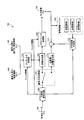
- FIG. 7 is a block diagram illustrating a functional configuration of the image decoding unit 700 of the image decoding apparatus according to the third embodiment.
- the image decoding unit 700 receives the encoded data S (v) 104 to be decoded from the image encoding apparatus 100 according to the first embodiment via a network or a storage medium, and determines the viewpoint of the decoding target image.
- a parallax image is generated from information based on a parallax image of another viewpoint different from the viewpoint.
- the encoded data S (v) 104 to be decoded includes residual information and filter information codes as in the second embodiment.
- the image decoding unit 700 includes a variable length decoding unit 704, a decoding method switching unit 701, an inverse transform / inverse quantization unit 714, an adder 715, and a prediction
- An image generation unit 712, a prefilter processing unit 710, an image synthesis unit 709, a post filter processing unit 706, and a reference image buffer 703 are provided.
- variable length decoding unit 704 the inverse transform / inverse quantization unit 714, and the prefilter processing unit 710 are the same as those in the second embodiment.
- the decoding method switching unit 701 is provided, and the composite image to which the post filter is applied by the post filter processing unit 706 is not stored in the reference image buffer 703.
- the decoding method switching unit 701 switches between the first decoding method and the second decoding method based on the viewpoint of the decoding target image.
- a decoded parallax image R (v ′) 102 of another viewpoint different from the viewpoint in the decoding target image and the viewpoint of the parallax image R (v ′) are decoded.
- the encoded data S (v) 104 is decoded using the depth information or the parallax information D (v ′) 103.
- the encoded data S (v) 104 is decoded without using the decoded parallax image R (v ′), the decoded depth information, or the parallax information D (v ′). It is a method to do.
- the image synthesis unit 709 converts the synthesized image (the parallax image at the viewpoint of the decoding target image) into the decoded parallax image R (v ′ ), Generated from the decoded depth information or disparity information D (v ′).
- the post filter processing unit 706 is included in the encoded data S (v) 104 with respect to the synthesized image generated by the image synthesizing unit 709 when the decoding method switching unit 701 switches to the first decoding method. Post filter processing is performed using the filter information, and the composite image after the post filter processing is output as an output image D (v) 702.
- the predicted image generation unit 712 generates a predicted image signal without using the synthesized image as a reference image when the decoding method switching unit 701 switches to the second decoding method.
- the adder 715 when switched to the second decoding method, adds the decoded encoded data S (v) 104 and the predicted image signal to generate an output image signal. This output image signal is stored in the reference image buffer 703.
- FIG. 8 is a diagram illustrating an example of encoding a multi-parallax image by image synthesis.
- the decoding method switching unit 701 switches to the second decoding method.
- the image decoding unit 700 adds the predicted image signal generated by the predicted image generation unit 712 to the residual signal obtained by the variable length decoding unit 704 and the inverse transform / inverse quantization unit 714.
- the parallax image of the target viewpoint is decoded.
- the decoding method switching unit 701 switches to the first decoding method. Then, the image decoding unit 700 generates a central viewpoint parallax image by image synthesis from the decoded left viewpoint and right viewpoint parallax images, and the variable length decoding unit 704 performs the same as in the second embodiment. According to the acquired filter information, a post-filter process is performed to decode the parallax image at the central viewpoint.
- the decoding method since the decoding method is switched according to the viewpoint of the decoding target image, the image quality can be further improved according to the viewpoint, and the encoding efficiency can be improved. it can.
- the configurations of the image decoding apparatus 500 according to the second embodiment and the image decoding unit 700 according to the third embodiment are not limited to the configurations described in the embodiment, for example, the prefilter processing unit 510. 710 or post filter processing units 506 and 706 may be used. In this case, only filter information relating to the filter to be used may be added to the encoded data S (v) 104.
- the first to third embodiments are also applicable to a case where a plurality of filters are switched for each region or application / non-application of a single filter is switched according to the nature of the local region of the image. Can do. That is, filter information such as application / non-application of a filter, the number of pixels used for the filter, and filter coefficients may be switched in units of pictures, slices, or blocks.
- the image encoding device 100 may be configured to add the filter information to the encoded data S (v) 104 for each processing unit for switching the filter. Further, the image decoding apparatus 500 and the image decoding unit 700 may be configured to apply the filter processing according to the filter information added to the encoded data S (v) 104.
- the present invention can also be applied to cases where input is made.
- the filter information used in the prefilter processing units 110, 510, and 710 is not limited to using a common filter for each data.
- different filters are used for parallax images and depth information. Can be applied.
- each filter to be used is encoded as filter information and transmitted to the image decoding device 500 and the image decoding unit 700 side.
- the filters applied by the image encoding units 117 are not limited to using a common filter, and different filters may be applied.
- the image encoding program executed by the image encoding device 100 according to the first embodiment, the image decoding device 500 according to the second and third embodiments, and the image decoding program executed by the image decoding unit 700 are ROM. Etc. provided in advance.
- the image encoding program executed by the image encoding device 100 according to the first embodiment, the image decoding device 500 according to the second embodiment, and the image decoding program executed by the image decoding unit 700 according to the third embodiment are: It is configured to be recorded on a computer-readable recording medium such as a CD-ROM, a flexible disk (FD), a CD-R, a DVD (Digital Versatile Disk), etc. in an installable or executable format file. May be.
- a computer-readable recording medium such as a CD-ROM, a flexible disk (FD), a CD-R, a DVD (Digital Versatile Disk), etc.
- an image encoding program executed by the image encoding device 100 according to the first embodiment, an image decoding device 500 according to the second embodiment, and an image decoding program executed by the image decoding unit 700 according to the third embodiment May be stored on a computer connected to a network such as the Internet and provided by being downloaded via the network.
- an image encoding program executed by the image encoding device 100 according to the first embodiment, an image decoding device 500 according to the second embodiment, and an image decoding program executed by the image decoding unit 700 according to the third embodiment. May be provided or distributed via a network such as the Internet.
- the image encoding program executed by the image encoding apparatus 100 according to Embodiment 1 includes the above-described units (subtractor, transform / quantization unit, variable-length encoding unit, inverse transform / inverse quantization unit, adder,
- the module configuration includes a prediction image generation unit, a pre-filter processing unit, an image synthesis unit, and a post-filter processing unit.
- a CPU processor
- each unit of the image encoding device 100 may be configured by hardware such as a circuit.
- the image decoding program executed by the image decoding apparatus 500 according to the second embodiment and the image decoding unit 700 according to the third embodiment includes the above-described units (variable length decoding unit, inverse transform / inverse quantization unit, addition) Module, a prediction image generation unit, a pre-filter processing unit, an image synthesis unit, and a post-filter processing unit).
- a CPU processor
- the above-described units are loaded onto the main storage device, and a variable-length decoding unit, an inverse transform / inverse quantization unit, an adder, a predicted image generation unit, a prefilter processing unit, an image synthesis unit, and post filter processing Are generated on the main memory.
- Each unit of the image decoding apparatus 500 and the image decoding unit 700 may be configured by hardware such as a circuit.
Landscapes
- Engineering & Computer Science (AREA)
- Multimedia (AREA)
- Signal Processing (AREA)
- Physics & Mathematics (AREA)
- General Physics & Mathematics (AREA)
- Theoretical Computer Science (AREA)
- Compression Or Coding Systems Of Tv Signals (AREA)
- Testing, Inspecting, Measuring Of Stereoscopic Televisions And Televisions (AREA)
Abstract
La présente invention se rapporte à un dispositif de codage d'image comprenant : un module de synthèse d'image, qui génère une première image avec parallaxe d'un point de vue dans une image cible de codage, au moyen d'au moins unes d'informations de profondeur et d'informations de parallaxe dans une seconde image avec parallaxe d'un autre point de vue différent ; un premier module de traitement par filtrage, qui réalise une opération de filtrage sur la première image avec parallaxe générée, sur la base de premières informations de filtrage ; un module de génération d'image de prédiction, pour générer une image de prédiction avec la première image avec parallaxe traitée par filtrage en tant qu'une image de référence ; et un module de codage, pour générer des données de codage à partir de l'image de prédiction et d'une image d'entrée.
Priority Applications (3)
| Application Number | Priority Date | Filing Date | Title |
|---|---|---|---|
| JP2012534879A JPWO2012131895A1 (ja) | 2011-03-29 | 2011-03-29 | 画像符号化装置、方法及びプログラム、画像復号化装置、方法及びプログラム |
| PCT/JP2011/057782 WO2012131895A1 (fr) | 2011-03-29 | 2011-03-29 | Dispositif, procédé et programme de codage d'image, et dispositif, procédé et programme de décodage d'image |
| US13/826,281 US20130195350A1 (en) | 2011-03-29 | 2013-03-14 | Image encoding device, image encoding method, image decoding device, image decoding method, and computer program product |
Applications Claiming Priority (1)
| Application Number | Priority Date | Filing Date | Title |
|---|---|---|---|
| PCT/JP2011/057782 WO2012131895A1 (fr) | 2011-03-29 | 2011-03-29 | Dispositif, procédé et programme de codage d'image, et dispositif, procédé et programme de décodage d'image |
Related Child Applications (1)
| Application Number | Title | Priority Date | Filing Date |
|---|---|---|---|
| US13/826,281 Continuation US20130195350A1 (en) | 2011-03-29 | 2013-03-14 | Image encoding device, image encoding method, image decoding device, image decoding method, and computer program product |
Publications (1)
| Publication Number | Publication Date |
|---|---|
| WO2012131895A1 true WO2012131895A1 (fr) | 2012-10-04 |
Family
ID=46929728
Family Applications (1)
| Application Number | Title | Priority Date | Filing Date |
|---|---|---|---|
| PCT/JP2011/057782 Ceased WO2012131895A1 (fr) | 2011-03-29 | 2011-03-29 | Dispositif, procédé et programme de codage d'image, et dispositif, procédé et programme de décodage d'image |
Country Status (3)
| Country | Link |
|---|---|
| US (1) | US20130195350A1 (fr) |
| JP (1) | JPWO2012131895A1 (fr) |
| WO (1) | WO2012131895A1 (fr) |
Cited By (1)
| Publication number | Priority date | Publication date | Assignee | Title |
|---|---|---|---|---|
| CN103813149A (zh) * | 2012-11-15 | 2014-05-21 | 中国科学院深圳先进技术研究院 | 一种编解码系统的图像与视频重构方法 |
Families Citing this family (25)
| Publication number | Priority date | Publication date | Assignee | Title |
|---|---|---|---|---|
| JP2014082541A (ja) * | 2012-10-12 | 2014-05-08 | National Institute Of Information & Communication Technology | 互いに類似した情報を含む複数画像のデータサイズを低減する方法、プログラムおよび装置 |
| WO2015115946A1 (fr) * | 2014-01-30 | 2015-08-06 | Telefonaktiebolaget L M Ericsson (Publ) | Procédés d'encodage/décodage de contenu vidéo tridimensionnel |
| US10262426B2 (en) | 2014-10-31 | 2019-04-16 | Fyusion, Inc. | System and method for infinite smoothing of image sequences |
| US9940541B2 (en) | 2015-07-15 | 2018-04-10 | Fyusion, Inc. | Artificially rendering images using interpolation of tracked control points |
| US10726593B2 (en) * | 2015-09-22 | 2020-07-28 | Fyusion, Inc. | Artificially rendering images using viewpoint interpolation and extrapolation |
| US10275935B2 (en) | 2014-10-31 | 2019-04-30 | Fyusion, Inc. | System and method for infinite synthetic image generation from multi-directional structured image array |
| US10176592B2 (en) | 2014-10-31 | 2019-01-08 | Fyusion, Inc. | Multi-directional structured image array capture on a 2D graph |
| US11095869B2 (en) | 2015-09-22 | 2021-08-17 | Fyusion, Inc. | System and method for generating combined embedded multi-view interactive digital media representations |
| US10242474B2 (en) | 2015-07-15 | 2019-03-26 | Fyusion, Inc. | Artificially rendering images using viewpoint interpolation and extrapolation |
| US12495134B2 (en) | 2015-07-15 | 2025-12-09 | Fyusion, Inc. | Drone based capture of multi-view interactive digital media |
| US12261990B2 (en) | 2015-07-15 | 2025-03-25 | Fyusion, Inc. | System and method for generating combined embedded multi-view interactive digital media representations |
| US11006095B2 (en) | 2015-07-15 | 2021-05-11 | Fyusion, Inc. | Drone based capture of a multi-view interactive digital media |
| US10852902B2 (en) | 2015-07-15 | 2020-12-01 | Fyusion, Inc. | Automatic tagging of objects on a multi-view interactive digital media representation of a dynamic entity |
| US10222932B2 (en) | 2015-07-15 | 2019-03-05 | Fyusion, Inc. | Virtual reality environment based manipulation of multilayered multi-view interactive digital media representations |
| US10147211B2 (en) | 2015-07-15 | 2018-12-04 | Fyusion, Inc. | Artificially rendering images using viewpoint interpolation and extrapolation |
| US11783864B2 (en) | 2015-09-22 | 2023-10-10 | Fyusion, Inc. | Integration of audio into a multi-view interactive digital media representation |
| US12587689B2 (en) * | 2016-10-04 | 2026-03-24 | B1 Institute Of Image Technology, Inc. | Method and apparatus for reconstructing 360-degree image according to projection format |
| KR102224668B1 (ko) * | 2016-10-04 | 2021-03-08 | 김기백 | 영상 데이터 부호화/복호화 방법 및 장치 |
| US11202017B2 (en) | 2016-10-06 | 2021-12-14 | Fyusion, Inc. | Live style transfer on a mobile device |
| US10437879B2 (en) | 2017-01-18 | 2019-10-08 | Fyusion, Inc. | Visual search using multi-view interactive digital media representations |
| US20180227482A1 (en) | 2017-02-07 | 2018-08-09 | Fyusion, Inc. | Scene-aware selection of filters and effects for visual digital media content |
| US10313651B2 (en) | 2017-05-22 | 2019-06-04 | Fyusion, Inc. | Snapshots at predefined intervals or angles |
| US11069147B2 (en) | 2017-06-26 | 2021-07-20 | Fyusion, Inc. | Modification of multi-view interactive digital media representation |
| US10592747B2 (en) | 2018-04-26 | 2020-03-17 | Fyusion, Inc. | Method and apparatus for 3-D auto tagging |
| CN112053434B (zh) * | 2020-09-28 | 2022-12-27 | 广州极飞科技股份有限公司 | 视差图的生成方法、三维重建方法及相关装置 |
Citations (4)
| Publication number | Priority date | Publication date | Assignee | Title |
|---|---|---|---|---|
| JPH06311506A (ja) * | 1992-12-25 | 1994-11-04 | Mitsubishi Electric Corp | フレーム間符号化処理方式及びフレーム間符号化処理方法及び符号化制御方式 |
| JP2009095066A (ja) * | 2009-02-03 | 2009-04-30 | Toshiba Corp | 動画像復号化装置、動画像復号化方法、動画像符号化装置、および動画像符号化方法 |
| JP2009544222A (ja) * | 2006-07-18 | 2009-12-10 | トムソン ライセンシング | 適応的参照フィルタリングの方法及び装置 |
| JP2011509053A (ja) * | 2008-01-07 | 2011-03-17 | トムソン ライセンシング | パラメトリックフィルタリングを使用したビデオ符号化及び復号化方法及び装置 |
Family Cites Families (21)
| Publication number | Priority date | Publication date | Assignee | Title |
|---|---|---|---|---|
| US6163337A (en) * | 1996-04-05 | 2000-12-19 | Matsushita Electric Industrial Co., Ltd. | Multi-view point image transmission method and multi-view point image display method |
| JPH11168730A (ja) * | 1997-12-04 | 1999-06-22 | Nec Corp | 画像圧縮装置 |
| JPH11331613A (ja) * | 1998-05-20 | 1999-11-30 | Matsushita Electric Ind Co Ltd | 階層型映像信号符号化装置と階層型映像信号復号化装置 |
| JP3708532B2 (ja) * | 2003-09-08 | 2005-10-19 | 日本電信電話株式会社 | ステレオ動画像符号化方法および装置と、ステレオ動画像符号化処理用プログラムおよびそのプログラムの記録媒体 |
| US8384763B2 (en) * | 2005-07-26 | 2013-02-26 | Her Majesty the Queen in right of Canada as represented by the Minster of Industry, Through the Communications Research Centre Canada | Generating a depth map from a two-dimensional source image for stereoscopic and multiview imaging |
| EP1946563A2 (fr) * | 2005-10-19 | 2008-07-23 | Thomson Licensing | Codage video multi-vue utilisant le codage video a produit scalaire |
| JP2007166381A (ja) * | 2005-12-15 | 2007-06-28 | Univ Of Tokyo | 多視点画像の圧縮符号化方法及び復号化方法 |
| JP2007180981A (ja) * | 2005-12-28 | 2007-07-12 | Victor Co Of Japan Ltd | 画像符号化装置、画像符号化方法、及び画像符号化プログラム |
| CN101346998B (zh) * | 2006-01-05 | 2012-01-11 | 日本电信电话株式会社 | 视频编码方法及解码方法、其装置 |
| JP4786585B2 (ja) * | 2007-04-20 | 2011-10-05 | Kddi株式会社 | 多視点映像符号化装置 |
| WO2009079760A1 (fr) * | 2007-12-20 | 2009-07-02 | Ati Technologies Ulc | Procédé, dispositif et support lisible par machine permettant de décrire un traitement vidéo |
| JP4944046B2 (ja) * | 2008-01-07 | 2012-05-30 | 日本電信電話株式会社 | 映像符号化方法,復号方法,符号化装置,復号装置,それらのプログラムおよびコンピュータ読み取り可能な記録媒体 |
| WO2010010943A1 (fr) * | 2008-07-25 | 2010-01-28 | ソニー株式会社 | Dispositif de traitement d'images et son procédé |
| EP2328337A4 (fr) * | 2008-09-02 | 2011-08-10 | Huawei Device Co Ltd | Procédé de communication d'une vidéo 3d, équipement de transmission, système, et procédé et système de reconstruction d'une image vidéo |
| JP2010157822A (ja) * | 2008-12-26 | 2010-07-15 | Victor Co Of Japan Ltd | 画像復号装置、画像符復号方法およびそのプログラム |
| US8750632B2 (en) * | 2008-12-26 | 2014-06-10 | JVC Kenwood Corporation | Apparatus and method for encoding images from multiple viewpoints and associated depth information |
| WO2010116614A1 (fr) * | 2009-03-30 | 2010-10-14 | 日本電気株式会社 | Dispositif d'affichage d'image, dispositif de génération d'image, procédé d'affichage d'image, procédé de génération d'image et support lisible par ordinateur non transitoire dans lequel est stocké un programme |
| JP2011049740A (ja) * | 2009-08-26 | 2011-03-10 | Sony Corp | 画像処理装置および方法 |
| US20110122225A1 (en) * | 2009-11-23 | 2011-05-26 | General Instrument Corporation | Depth Coding as an Additional Channel to Video Sequence |
| CN102884802B (zh) * | 2010-03-24 | 2014-03-12 | 富士胶片株式会社 | 三维成像装置和视点图像恢复方法 |
| CN102907106A (zh) * | 2010-05-28 | 2013-01-30 | 日立民用电子株式会社 | 接收装置和输出方法 |
-
2011
- 2011-03-29 JP JP2012534879A patent/JPWO2012131895A1/ja active Pending
- 2011-03-29 WO PCT/JP2011/057782 patent/WO2012131895A1/fr not_active Ceased
-
2013
- 2013-03-14 US US13/826,281 patent/US20130195350A1/en not_active Abandoned
Patent Citations (4)
| Publication number | Priority date | Publication date | Assignee | Title |
|---|---|---|---|---|
| JPH06311506A (ja) * | 1992-12-25 | 1994-11-04 | Mitsubishi Electric Corp | フレーム間符号化処理方式及びフレーム間符号化処理方法及び符号化制御方式 |
| JP2009544222A (ja) * | 2006-07-18 | 2009-12-10 | トムソン ライセンシング | 適応的参照フィルタリングの方法及び装置 |
| JP2011509053A (ja) * | 2008-01-07 | 2011-03-17 | トムソン ライセンシング | パラメトリックフィルタリングを使用したビデオ符号化及び復号化方法及び装置 |
| JP2009095066A (ja) * | 2009-02-03 | 2009-04-30 | Toshiba Corp | 動画像復号化装置、動画像復号化方法、動画像符号化装置、および動画像符号化方法 |
Cited By (2)
| Publication number | Priority date | Publication date | Assignee | Title |
|---|---|---|---|---|
| CN103813149A (zh) * | 2012-11-15 | 2014-05-21 | 中国科学院深圳先进技术研究院 | 一种编解码系统的图像与视频重构方法 |
| CN103813149B (zh) * | 2012-11-15 | 2016-04-13 | 中国科学院深圳先进技术研究院 | 一种编解码系统的图像与视频重构方法 |
Also Published As
| Publication number | Publication date |
|---|---|
| US20130195350A1 (en) | 2013-08-01 |
| JPWO2012131895A1 (ja) | 2014-07-24 |
Similar Documents
| Publication | Publication Date | Title |
|---|---|---|
| JPWO2012131895A1 (ja) | 画像符号化装置、方法及びプログラム、画像復号化装置、方法及びプログラム | |
| JP7491985B2 (ja) | 多視点信号コーデック | |
| JP5902814B2 (ja) | 映像符号化方法および装置、映像復号方法および装置、及びそれらのプログラム | |
| EP2241112B1 (fr) | Codage de coefficients de filtre adaptatif | |
| CN101325713B (zh) | 使用彩色间补偿来编码和解码图像的方法和装置 | |
| KR20220162786A (ko) | 비디오 코딩에서 심층 신경 네트워크 기반 인터프레임 예측을 위한 방법 및 장치 | |
| JP6042899B2 (ja) | 映像符号化方法および装置、映像復号方法および装置、それらのプログラム及び記録媒体 | |
| JP6409516B2 (ja) | ピクチャ符号化プログラム、ピクチャ符号化方法及びピクチャ符号化装置 | |
| WO2004059980A1 (fr) | Procede et appareil de codage et de decodage de video stereoscopique | |
| CN106664430A (zh) | 利用嵌入块分割对视频信号进行编码和解码的方法及装置 | |
| WO2008020734A1 (fr) | Procédé et appareil de codage ou de décodage de trames de différentes vues, dans une vidéo multivue, au moyen d'une disparité globale | |
| KR20090039720A (ko) | 적응적 참조 필터링을 위한 방법 및 장치 | |
| CN101009839A (zh) | 基于正交变换和向量量化的视频编码/解码的方法和设备 | |
| CN108353175A (zh) | 使用系数引起的预测处理视频信号的方法和装置 | |
| WO2009133845A1 (fr) | Dispositif et procédé de codage/décodage vidéo | |
| CN104885462A (zh) | 视频编码装置和方法、视频解码装置和方法、以及其程序 | |
| JPWO2010055675A1 (ja) | 動画像符号化装置及び動画像復号装置 | |
| KR20070075354A (ko) | 비디오 신호의 디코딩/인코딩 방법 및 장치 | |
| CN105052148B (zh) | 视频编码装置和方法、视频解码装置和方法、以及其记录介质 | |
| HK40062696A (en) | Decoding of a multi-view video signal | |
| CN118235393A (zh) | 用于使用亮度进行色度帧内预测模式的下采样滤波器的信令 | |
| WO2009133938A1 (fr) | Dispositif de codage et de décodage d'image variable dans le temps |
Legal Events
| Date | Code | Title | Description |
|---|---|---|---|
| ENP | Entry into the national phase |
Ref document number: 2012534879 Country of ref document: JP Kind code of ref document: A |
|
| 121 | Ep: the epo has been informed by wipo that ep was designated in this application |
Ref document number: 11862038 Country of ref document: EP Kind code of ref document: A1 |
|
| NENP | Non-entry into the national phase |
Ref country code: DE |
|
| 122 | Ep: pct application non-entry in european phase |
Ref document number: 11862038 Country of ref document: EP Kind code of ref document: A1 |