WO2012131907A1 - Affichage tête haute et mécanisme d'alarme - Google Patents
Affichage tête haute et mécanisme d'alarme Download PDFInfo
- Publication number
- WO2012131907A1 WO2012131907A1 PCT/JP2011/057833 JP2011057833W WO2012131907A1 WO 2012131907 A1 WO2012131907 A1 WO 2012131907A1 JP 2011057833 W JP2011057833 W JP 2011057833W WO 2012131907 A1 WO2012131907 A1 WO 2012131907A1
- Authority
- WO
- WIPO (PCT)
- Prior art keywords
- attachment portion
- display
- head
- attachment
- mounting
- Prior art date
- Legal status (The legal status is an assumption and is not a legal conclusion. Google has not performed a legal analysis and makes no representation as to the accuracy of the status listed.)
- Ceased
Links
Images



Classifications
-
- G—PHYSICS
- G02—OPTICS
- G02B—OPTICAL ELEMENTS, SYSTEMS OR APPARATUS
- G02B27/00—Optical systems or apparatus not provided for by any of the groups G02B1/00 - G02B26/00, G02B30/00
- G02B27/01—Head-up displays
-
- B—PERFORMING OPERATIONS; TRANSPORTING
- B60—VEHICLES IN GENERAL
- B60K—ARRANGEMENT OR MOUNTING OF PROPULSION UNITS OR OF TRANSMISSIONS IN VEHICLES; ARRANGEMENT OR MOUNTING OF PLURAL DIVERSE PRIME-MOVERS IN VEHICLES; AUXILIARY DRIVES FOR VEHICLES; INSTRUMENTATION OR DASHBOARDS FOR VEHICLES; ARRANGEMENTS IN CONNECTION WITH COOLING, AIR INTAKE, GAS EXHAUST OR FUEL SUPPLY OF PROPULSION UNITS IN VEHICLES
- B60K35/00—Instruments specially adapted for vehicles; Arrangement of instruments in or on vehicles
- B60K35/20—Output arrangements, i.e. from vehicle to user, associated with vehicle functions or specially adapted therefor
- B60K35/21—Output arrangements, i.e. from vehicle to user, associated with vehicle functions or specially adapted therefor using visual output, e.g. blinking lights or matrix displays
- B60K35/23—Head-up displays [HUD]
-
- B—PERFORMING OPERATIONS; TRANSPORTING
- B60—VEHICLES IN GENERAL
- B60K—ARRANGEMENT OR MOUNTING OF PROPULSION UNITS OR OF TRANSMISSIONS IN VEHICLES; ARRANGEMENT OR MOUNTING OF PLURAL DIVERSE PRIME-MOVERS IN VEHICLES; AUXILIARY DRIVES FOR VEHICLES; INSTRUMENTATION OR DASHBOARDS FOR VEHICLES; ARRANGEMENTS IN CONNECTION WITH COOLING, AIR INTAKE, GAS EXHAUST OR FUEL SUPPLY OF PROPULSION UNITS IN VEHICLES
- B60K35/00—Instruments specially adapted for vehicles; Arrangement of instruments in or on vehicles
- B60K35/20—Output arrangements, i.e. from vehicle to user, associated with vehicle functions or specially adapted therefor
- B60K35/26—Output arrangements, i.e. from vehicle to user, associated with vehicle functions or specially adapted therefor using acoustic output
-
- B—PERFORMING OPERATIONS; TRANSPORTING
- B60—VEHICLES IN GENERAL
- B60K—ARRANGEMENT OR MOUNTING OF PROPULSION UNITS OR OF TRANSMISSIONS IN VEHICLES; ARRANGEMENT OR MOUNTING OF PLURAL DIVERSE PRIME-MOVERS IN VEHICLES; AUXILIARY DRIVES FOR VEHICLES; INSTRUMENTATION OR DASHBOARDS FOR VEHICLES; ARRANGEMENTS IN CONNECTION WITH COOLING, AIR INTAKE, GAS EXHAUST OR FUEL SUPPLY OF PROPULSION UNITS IN VEHICLES
- B60K35/00—Instruments specially adapted for vehicles; Arrangement of instruments in or on vehicles
- B60K35/20—Output arrangements, i.e. from vehicle to user, associated with vehicle functions or specially adapted therefor
- B60K35/28—Output arrangements, i.e. from vehicle to user, associated with vehicle functions or specially adapted therefor characterised by the type of the output information, e.g. video entertainment or vehicle dynamics information; characterised by the purpose of the output information, e.g. for attracting the attention of the driver
-
- B—PERFORMING OPERATIONS; TRANSPORTING
- B60—VEHICLES IN GENERAL
- B60K—ARRANGEMENT OR MOUNTING OF PROPULSION UNITS OR OF TRANSMISSIONS IN VEHICLES; ARRANGEMENT OR MOUNTING OF PLURAL DIVERSE PRIME-MOVERS IN VEHICLES; AUXILIARY DRIVES FOR VEHICLES; INSTRUMENTATION OR DASHBOARDS FOR VEHICLES; ARRANGEMENTS IN CONNECTION WITH COOLING, AIR INTAKE, GAS EXHAUST OR FUEL SUPPLY OF PROPULSION UNITS IN VEHICLES
- B60K35/00—Instruments specially adapted for vehicles; Arrangement of instruments in or on vehicles
- B60K35/50—Instruments characterised by their means of attachment to or integration in the vehicle
-
- B—PERFORMING OPERATIONS; TRANSPORTING
- B60—VEHICLES IN GENERAL
- B60K—ARRANGEMENT OR MOUNTING OF PROPULSION UNITS OR OF TRANSMISSIONS IN VEHICLES; ARRANGEMENT OR MOUNTING OF PLURAL DIVERSE PRIME-MOVERS IN VEHICLES; AUXILIARY DRIVES FOR VEHICLES; INSTRUMENTATION OR DASHBOARDS FOR VEHICLES; ARRANGEMENTS IN CONNECTION WITH COOLING, AIR INTAKE, GAS EXHAUST OR FUEL SUPPLY OF PROPULSION UNITS IN VEHICLES
- B60K35/00—Instruments specially adapted for vehicles; Arrangement of instruments in or on vehicles
- B60K35/60—Instruments characterised by their location or relative disposition in or on vehicles
-
- G—PHYSICS
- G02—OPTICS
- G02B—OPTICAL ELEMENTS, SYSTEMS OR APPARATUS
- G02B27/00—Optical systems or apparatus not provided for by any of the groups G02B1/00 - G02B26/00, G02B30/00
- G02B27/01—Head-up displays
- G02B27/0149—Head-up displays characterised by mechanical features
-
- B—PERFORMING OPERATIONS; TRANSPORTING
- B60—VEHICLES IN GENERAL
- B60K—ARRANGEMENT OR MOUNTING OF PROPULSION UNITS OR OF TRANSMISSIONS IN VEHICLES; ARRANGEMENT OR MOUNTING OF PLURAL DIVERSE PRIME-MOVERS IN VEHICLES; AUXILIARY DRIVES FOR VEHICLES; INSTRUMENTATION OR DASHBOARDS FOR VEHICLES; ARRANGEMENTS IN CONNECTION WITH COOLING, AIR INTAKE, GAS EXHAUST OR FUEL SUPPLY OF PROPULSION UNITS IN VEHICLES
- B60K2360/00—Indexing scheme associated with groups B60K35/00 or B60K37/00 relating to details of instruments or dashboards
- B60K2360/20—Optical features of instruments
- B60K2360/27—Optical features of instruments using semi-transparent optical elements
-
- B—PERFORMING OPERATIONS; TRANSPORTING
- B60—VEHICLES IN GENERAL
- B60K—ARRANGEMENT OR MOUNTING OF PROPULSION UNITS OR OF TRANSMISSIONS IN VEHICLES; ARRANGEMENT OR MOUNTING OF PLURAL DIVERSE PRIME-MOVERS IN VEHICLES; AUXILIARY DRIVES FOR VEHICLES; INSTRUMENTATION OR DASHBOARDS FOR VEHICLES; ARRANGEMENTS IN CONNECTION WITH COOLING, AIR INTAKE, GAS EXHAUST OR FUEL SUPPLY OF PROPULSION UNITS IN VEHICLES
- B60K2360/00—Indexing scheme associated with groups B60K35/00 or B60K37/00 relating to details of instruments or dashboards
- B60K2360/20—Optical features of instruments
- B60K2360/33—Illumination features
- B60K2360/334—Projection means
-
- B—PERFORMING OPERATIONS; TRANSPORTING
- B60—VEHICLES IN GENERAL
- B60K—ARRANGEMENT OR MOUNTING OF PROPULSION UNITS OR OF TRANSMISSIONS IN VEHICLES; ARRANGEMENT OR MOUNTING OF PLURAL DIVERSE PRIME-MOVERS IN VEHICLES; AUXILIARY DRIVES FOR VEHICLES; INSTRUMENTATION OR DASHBOARDS FOR VEHICLES; ARRANGEMENTS IN CONNECTION WITH COOLING, AIR INTAKE, GAS EXHAUST OR FUEL SUPPLY OF PROPULSION UNITS IN VEHICLES
- B60K2360/00—Indexing scheme associated with groups B60K35/00 or B60K37/00 relating to details of instruments or dashboards
- B60K2360/77—Instrument locations other than the dashboard
- B60K2360/771—Instrument locations other than the dashboard on the ceiling
-
- B—PERFORMING OPERATIONS; TRANSPORTING
- B60—VEHICLES IN GENERAL
- B60Y—INDEXING SCHEME RELATING TO ASPECTS CROSS-CUTTING VEHICLE TECHNOLOGY
- B60Y2304/00—Optimising design; Manufacturing; Testing
- B60Y2304/09—Testing or calibrating during manufacturing
-
- F—MECHANICAL ENGINEERING; LIGHTING; HEATING; WEAPONS; BLASTING
- F16—ENGINEERING ELEMENTS AND UNITS; GENERAL MEASURES FOR PRODUCING AND MAINTAINING EFFECTIVE FUNCTIONING OF MACHINES OR INSTALLATIONS; THERMAL INSULATION IN GENERAL
- F16B—DEVICES FOR FASTENING OR SECURING CONSTRUCTIONAL ELEMENTS OR MACHINE PARTS TOGETHER, e.g. NAILS, BOLTS, CIRCLIPS, CLAMPS, CLIPS OR WEDGES; JOINTS OR JOINTING
- F16B31/00—Screwed connections specially modified in view of tensile load; Break-bolts
- F16B31/02—Screwed connections specially modified in view of tensile load; Break-bolts for indicating the attainment of a particular tensile load or limiting tensile load
Definitions
- the present invention relates to a head-up display installed on a moving body.
- Patent Document 1 discloses a head-up display that includes a display device and a combiner and is installed on a vehicle interior ceiling.
- the head-up display is fixed to the mounted portion on the vehicle body side with a screw at the ceiling of the passenger compartment.
- An object of this invention is to provide the head up display which can alert
- the invention according to claim 1 is a head-up display mounted on a moving body, wherein a light source unit that projects light onto a display unit to form a virtual image, and between the display unit and the light source unit An attachment portion for attaching the head-up display to the attachment portion of the moving body, and provided between the attachment portion and the attachment portion, and the attachment portion and the attachment portion. And a notifying member that generates sound between the attachment portion and the attached portion when the interval is larger than a predetermined value.
- the invention according to claim 10 is a head-up display, and is provided between an attachment portion for attaching an attachment object to the attachment portion, the attachment portion and the attachment portion, and And a notifying member that generates sound between the attachment portion and the attached portion when the interval between the attachment portion and the attachment portion is equal to or greater than a predetermined value.
- the invention according to claim 11 is a notification mechanism, which is provided between an attachment portion for attaching an attachment object to the attachment portion and the attachment portion, and the attachment portion and the attachment portion. It has an informing member which produces a sound by colliding with at least any one of the above-mentioned attaching part or the above-mentioned attachment part because the interval with is a predetermined value or more.
- the invention according to claim 12 is a notification mechanism having a notification member provided between the attachment portion for attaching the attachment object to the attachment portion and the attachment portion, wherein the notification member is When the interval between the attachment portion and the attachment portion is equal to or greater than a predetermined value, a vibration is generated between the attachment portion and the attachment portion due to vibration applied to the notification member.
- a head-up display mounted on a moving body includes a light source unit that projects light onto a display unit to form a virtual image, and a space between the display unit and the light source unit.
- a notifying member that generates sound between the attachment portion and the attached portion when the interval is larger than a predetermined value.
- the above head-up display projects light from the light source onto the display unit, forms a virtual image, and makes the user visually recognize.
- the head-up display is attached to an attachment portion of a moving body such as a vehicle, for example, a bracket on the vehicle body side, by an attachment portion provided between the display portion and the light source portion.
- an informing member is provided between the attaching portion and the attached portion so as to generate a sound when the interval is larger than a predetermined value. Therefore, when the attachment strength between the attachment portion and the attachment portion decreases and the interval increases, this is notified by sound.
- the notifying member generates the sound by vibration applied to the notifying member. Further, the notification means does not generate the sound when the interval between the attached portion and the attachment portion is equal to or less than the predetermined value, and generates the sound when the interval is larger than the predetermined value.
- the notification member causes the sound by colliding against at least one of the attachment portion and the attachment portion.
- the head-up display has a mounting screw for mounting the mounting portion on the mounted portion
- the notification member has a through hole larger than the diameter of the mounting screw, and the mounting screw Is provided in a state of penetrating through the through hole.
- the notification member has a dome shape, and the top of the dome shape faces the attached portion side. Thereby, the collision sound is more likely to be reflected.
- the notification member is formed of a metal piece and a bell that covers the metal piece, and an interval between the attached portion and the attachment portion is equal to or less than the predetermined value.
- the metal piece is fixed by being sandwiched by the bell, and when the interval between the attached portion and the attachment portion is equal to or greater than the predetermined value, the metal piece by the bell is The sound is generated by releasing the fixation.
- the notification member is fixed to one end of an elastic member having a predetermined length, and is provided between the attachment portion and the attachment portion.
- the other end of the member is fixed to the mounting portion.
- the other end of the elastic member is fixed at a position where the attachment portion does not contact the attached portion when the attachment portion is attached to the attached portion.
- Another preferred embodiment of the present invention is a head-up display, which is provided between an attachment portion for attaching an attachment object to an attachment portion, and the attachment portion and the attachment portion. And a notifying member that generates a sound between the attachment portion and the attachment portion when the interval between the attachment portion and the attachment portion is larger than a predetermined value.
- the head-up display is attached to an attachment portion of a moving body such as a vehicle, for example, a bracket on the vehicle body side, by an attachment portion provided between the display portion and the light source portion.
- an informing member is provided between the attaching portion and the attached portion so as to generate a sound when the interval is larger than a predetermined value. Therefore, when the attachment strength between the attachment portion and the attachment portion decreases and the interval increases, this is notified by sound.
- Another preferred embodiment of the present invention is a notification mechanism, which is provided between an attachment portion for attaching an attachment object to the attachment portion and the attachment portion, and the attachment portion and the attachment portion.
- the information member has a notification member that generates a sound by colliding against at least one of the attachment portion and the attached portion.
- the notification mechanism generates a sound by colliding with the attached portion and / or the attaching portion when the attachment strength between the attaching portion and the attached portion is reduced and the interval is increased.
- Another preferred embodiment of the present invention is a notification mechanism having a notification member provided between an attachment portion for attaching an attachment object to the attachment portion and the attachment portion, and the notification member Is caused to generate a sound by vibrating between the mounting portion and the mounted portion by vibration applied to the notification member when the interval between the mounted portion and the mounting portion is a predetermined value or more. .
- the notification mechanism When the attachment strength between the attachment portion and the attachment portion decreases and the interval increases, the notification mechanism generates a sound by vibrating between the attachment portion and the attachment portion.
- FIG. 1 schematically shows a state in which the head-up display according to the embodiment is installed in a vehicle cabin.
- FIG. 1 is a side view of the driver's seat of the vehicle 1, and the driver 7 sits on the seat 5 in the passenger compartment.
- a windshield 4 of the vehicle 1 is located in front of the driver 7.
- the head-up display 10 is installed diagonally upward in front of the driver 7. Although details will be described later, the head-up display 10 includes a light source unit 11 and a combiner 12. As indicated by a broken line, the light emitted from the light source unit 11 is reflected by the combiner 12 and reaches the eyes of the driver 7. Accordingly, the driver 7 visually recognizes the virtual image 30 at a position in front of the vehicle. Note that the tip of the arrow of the virtual image 30 indicates the upward direction.
- FIG. 2 is a perspective view of the head-up display 10 according to the first embodiment when viewed obliquely from below
- FIG. 3 is a perspective view of the head-up display 10 viewed obliquely from above.
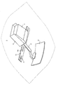
- the head-up display 10 includes a light source unit 11, a combiner 12, an arm 13, an attachment stay 14, and a holding member 15.
- the mounting stay 14 is a member that serves as a base when the head-up display 10 is attached to the vehicle.
- the mounting stay 14 is an elongated flat plate, and a plurality of long holes 14a are formed.
- the attachment stay 14 is attached to the bracket 20 provided on the vehicle body side by screws 21.
- the light source unit 11 is equipped with a light source (not shown) such as a laser diode.
- the light emitted from the light source unit 11 is projected to the combiner 12.
- the combiner 12 reflects the light emitted from the light source unit 11 toward the eyes of the driver 7.
- the light source unit 11 is fixed to the holding member 15 with, for example, screws.
- the holding member 15 is fixed to the mounting stay 14 with screws.
- the arm 13 is attached to the holding member 15.
- the arm 13 is provided with a combiner holding portion 13 a that holds the combiner 12 near the tip of the arm 13, that is, near the end opposite to the light source portion 11.
- the combiner 12 is an example of the display unit of the present invention
- the mounting stay 14 is an example of the mounting unit
- the bracket 20 provided on the vehicle body side is an example of the mounted unit
- the screw 21 is mounted. It is an example of a screw.
- a notification mechanism is configured by providing a washer 22 between the attachment stay 14 and the bracket 20 as shown in FIG. 3.
- FIG. 4 is a side view showing the structure of the notification mechanism of the first embodiment.
- each member is hatched.
- a washer 22 is disposed between the bracket 20 on the vehicle body side and the mounting stay 14 at the position of the elongated hole 14 a of the mounting stay 14.
- the washer 22 includes a through hole 22 a having a diameter larger than that of the screw 21.
- the screw 21 passes through the long hole 14 a of the mounting stay 14 and the through hole 22 a of the washer 22 and is screwed into a screw thread provided in the bracket 20.
- the bracket 20 and the mounting stay 14 have an interval Gx substantially equal to the thickness of the washer 22 (this interval is referred to as a “predetermined value Gx”).
- the gap G between the bracket 20 and the mounting stay 14 is a predetermined value shown in FIG. It becomes larger than Gx.
- the washer 22 vibrates as indicated by an arrow due to the vibration of the vehicle, and collides with the bracket 20 and / or the mounting stay 14 to generate abnormal noise. The user can know that the screw 21 is loose by this abnormal noise generated above the head.
- the flat plate washer 22 is used.
- a dome type washer 25 may be used as shown in FIG. 4D.
- the washer 25 also has a through hole having a diameter larger than the diameter of the screw 21. Due to its shape, the dome-shaped washer 25 has a structure in which the collision sound is more likely to be reflected than the flat washer 22.
- the dome-shaped washer 25 is arranged so that the top 25a faces the bracket 20 and the dome-shaped open end 25b faces the mounting stay 14.
- a washer is used for the purpose of stabilizing the seating surface in the case of fastening with a screw or fastening with a bolt and a nut.
- a washer is disposed between the screw 21 and the mounting stay 14.
- the washer 22 in the first embodiment is different from this and is used for the purpose of generating abnormal noise due to vibration when the mounting strength is reduced. It is arranged between the stay 14.
- FIG. 5 is a perspective view of a head-up display according to the second embodiment
- FIG. 6 is a side view showing a notification mechanism according to the second embodiment.
- each member is hatched.
- the second embodiment differs from the first embodiment in that a bell (tin) member 40 is used instead of the washer 22, but the basic structure of the head-up display 10 is the first embodiment. Similar to the example.
- the bell member 40 includes a plate spring 43 having elasticity, an ellipse bell 41 made of metal, for example, provided at one end of the plate spring 43, and a sphere 42 such as a metal piece sealed inside the bell body 41.
- the bell 41 and the sphere 42 are made of, for example, metal. It is preferable that the bell 41 has some elasticity. When the sphere 42 collides with the inner surface of the bell 41, an abnormal noise is generated.
- the other end of the leaf spring 43 is fixed to the mounting stay 14 with a screw 44.
- the bell 41 is fixed between the bracket 20 and the mounting stay 14 as shown in FIG. 6B. Since the bell 41 has a certain degree of elasticity, it is deformed by being sandwiched between the bracket 20 and the mounting stay 14, and the ball 42 is sandwiched and fixed between the inner surfaces (upper and lower surfaces) of the bell 41. In this state, even if vehicle vibration or the like occurs, the sphere 42 cannot vibrate and no abnormal noise is generated.
- the distance between the bracket 20 and the mounting stay 14 at this time is set to a predetermined value Gy.
- the gap G between the bracket 20 and the mounting stay 14 becomes larger than a predetermined value Gy as shown in FIG. 6C, and the fixation of the sphere 42 by the bell 41 is released. Is done.
- the vibration of the vehicle causes the leaf spring 43 to vibrate, the vibration is transmitted to the bell body 41, and the sphere 42 collides with the bell body 41, and abnormal noise is generated.
- the bell member 40 basically generates abnormal noise due to the collision between the bell 41 and the sphere 42. Therefore, unlike the first embodiment, even if the bell 41 does not collide with the bracket 20 or the mounting stay 14, an abnormal noise is generated if the leaf spring 43 vibrates due to the vibration of the vehicle. However, the bell 41 may collide with the bracket 20 or the mounting stay 14 to generate abnormal noise.
- vibrations generated by running of the vehicle generally have a frequency of about 10 to 30 Hz. Therefore, the length and thickness of the leaf spring 43 are adjusted so that the resonance frequency of the leaf spring 43 is within this range. By determining the spring constant, the leaf spring 43 can be vibrated more efficiently and abnormal noise can be easily generated.
- the other end of the leaf spring 43 is fixed to the mounting stay 14 with a screw 44, but may be fixed by other methods, for example, using a snap fit.
- the present invention can be used for a head-up display installed on a moving body such as a vehicle.
Landscapes
- Engineering & Computer Science (AREA)
- Chemical & Material Sciences (AREA)
- Combustion & Propulsion (AREA)
- Transportation (AREA)
- Mechanical Engineering (AREA)
- Physics & Mathematics (AREA)
- General Physics & Mathematics (AREA)
- Optics & Photonics (AREA)
- Fittings On The Vehicle Exterior For Carrying Loads, And Devices For Holding Or Mounting Articles (AREA)
- Instrument Panels (AREA)
Abstract
Selon l'invention, un affichage tête haute projette de la lumière provenant d'une source de lumière sur une unité d'affichage, formant ainsi une image virtuelle visible pour un utilisateur. Cet affichage tête haute est fixé à une partie de réception de fixation, notamment un support de montage, sur un côté carrosserie de véhicule d'un corps en déplacement, notamment un véhicule, à l'aide d'une partie de fixation située entre l'unité d'affichage et une unité de source lumineuse. Un élément d'alarme produit un son lorsque l'espace situé entre la partie de réception de fixation et la partie de fixation dépasse une valeur prédéfinie. Une rondelle, un élément en forme de cloche ou analogue peuvent servir d'élément d'alarme. Par conséquent, si la force de fixation entre la partie de fixation et la partie de réception de fixation diminue et ledit espace s'agrandit, l'utilisateur est informé de cet état de fait par un son.
Priority Applications (2)
| Application Number | Priority Date | Filing Date | Title |
|---|---|---|---|
| JP2011546365A JP4920805B1 (ja) | 2011-03-29 | 2011-03-29 | ヘッドアップディスプレイ及び報知機構 |
| PCT/JP2011/057833 WO2012131907A1 (fr) | 2011-03-29 | 2011-03-29 | Affichage tête haute et mécanisme d'alarme |
Applications Claiming Priority (1)
| Application Number | Priority Date | Filing Date | Title |
|---|---|---|---|
| PCT/JP2011/057833 WO2012131907A1 (fr) | 2011-03-29 | 2011-03-29 | Affichage tête haute et mécanisme d'alarme |
Publications (1)
| Publication Number | Publication Date |
|---|---|
| WO2012131907A1 true WO2012131907A1 (fr) | 2012-10-04 |
Family
ID=46243811
Family Applications (1)
| Application Number | Title | Priority Date | Filing Date |
|---|---|---|---|
| PCT/JP2011/057833 Ceased WO2012131907A1 (fr) | 2011-03-29 | 2011-03-29 | Affichage tête haute et mécanisme d'alarme |
Country Status (2)
| Country | Link |
|---|---|
| JP (1) | JP4920805B1 (fr) |
| WO (1) | WO2012131907A1 (fr) |
Citations (5)
| Publication number | Priority date | Publication date | Assignee | Title |
|---|---|---|---|---|
| JPS63164035U (fr) * | 1987-04-16 | 1988-10-26 | ||
| JPH02205736A (ja) * | 1989-02-03 | 1990-08-15 | Mitsui Eng & Shipbuild Co Ltd | ボルト・ナットのゆるみ検出方法 |
| JPH0577657A (ja) * | 1991-09-20 | 1993-03-30 | Fujitsu Ltd | 車両用表示装置 |
| JPH11132215A (ja) * | 1997-10-27 | 1999-05-18 | Nippon Signal Co Ltd:The | 締結具の締結確認装置 |
| JP2009236229A (ja) * | 2008-03-27 | 2009-10-15 | Toyota Motor Corp | ねじ部材の緩み警告構造 |
-
2011
- 2011-03-29 JP JP2011546365A patent/JP4920805B1/ja not_active Expired - Fee Related
- 2011-03-29 WO PCT/JP2011/057833 patent/WO2012131907A1/fr not_active Ceased
Patent Citations (5)
| Publication number | Priority date | Publication date | Assignee | Title |
|---|---|---|---|---|
| JPS63164035U (fr) * | 1987-04-16 | 1988-10-26 | ||
| JPH02205736A (ja) * | 1989-02-03 | 1990-08-15 | Mitsui Eng & Shipbuild Co Ltd | ボルト・ナットのゆるみ検出方法 |
| JPH0577657A (ja) * | 1991-09-20 | 1993-03-30 | Fujitsu Ltd | 車両用表示装置 |
| JPH11132215A (ja) * | 1997-10-27 | 1999-05-18 | Nippon Signal Co Ltd:The | 締結具の締結確認装置 |
| JP2009236229A (ja) * | 2008-03-27 | 2009-10-15 | Toyota Motor Corp | ねじ部材の緩み警告構造 |
Also Published As
| Publication number | Publication date |
|---|---|
| JPWO2012131907A1 (ja) | 2014-07-24 |
| JP4920805B1 (ja) | 2012-04-18 |
Similar Documents
| Publication | Publication Date | Title |
|---|---|---|
| US20200361398A1 (en) | External sensor attachment portion structure | |
| JP7435538B2 (ja) | 車載装置 | |
| JP6207803B2 (ja) | 超音波センサおよび障害物検知装置 | |
| JP2022170165A (ja) | 振動発生装置 | |
| JP6006130B2 (ja) | 表示装置及びテレビジョン受信機 | |
| US12185637B2 (en) | Vibration generation device | |
| JP4920805B1 (ja) | ヘッドアップディスプレイ及び報知機構 | |
| JP2019172147A (ja) | リアビューミラー装置、車載表示装置、車載表示システム | |
| JP5427095B2 (ja) | 防振装置 | |
| JP3733365B2 (ja) | 警報音発生装置 | |
| JP5229560B2 (ja) | ルームミラー装着型車載機器 | |
| CN210381291U (zh) | 移动终端 | |
| WO2014126257A1 (fr) | Appareil d'affichage tête haute | |
| JP2020085571A (ja) | センサ搭載構造 | |
| JP4904607B2 (ja) | 車両用スピーカーシステム | |
| JP2019116210A (ja) | 駆動装置の取付構造 | |
| CN107295431B (zh) | 扬声器单元 | |
| JP7346935B2 (ja) | 車載用スピーカ、スピーカシステム、および車両 | |
| JP2007145228A (ja) | 車両用のホーン | |
| JP5449091B2 (ja) | ダイナミックダンパ | |
| CN216789806U (zh) | 一种地铁信息显示屏的悬挂固定结构 | |
| JP2021024323A (ja) | 発音器の取付構造および発音器を取り付けた車両 | |
| JP7533969B2 (ja) | 車両用警報装置 | |
| JP2004264571A (ja) | 液晶表示装置 | |
| JP2021024322A (ja) | 発音器の取付構造および発音器を取り付けた車両 |
Legal Events
| Date | Code | Title | Description |
|---|---|---|---|
| ENP | Entry into the national phase |
Ref document number: 2011546365 Country of ref document: JP Kind code of ref document: A |
|
| 121 | Ep: the epo has been informed by wipo that ep was designated in this application |
Ref document number: 11862719 Country of ref document: EP Kind code of ref document: A1 |
|
| NENP | Non-entry into the national phase |
Ref country code: DE |
|
| 122 | Ep: pct application non-entry in european phase |
Ref document number: 11862719 Country of ref document: EP Kind code of ref document: A1 |