WO2012131972A1 - Batterie à électrolyte non aqueux - Google Patents
Batterie à électrolyte non aqueux Download PDFInfo
- Publication number
- WO2012131972A1 WO2012131972A1 PCT/JP2011/058200 JP2011058200W WO2012131972A1 WO 2012131972 A1 WO2012131972 A1 WO 2012131972A1 JP 2011058200 W JP2011058200 W JP 2011058200W WO 2012131972 A1 WO2012131972 A1 WO 2012131972A1
- Authority
- WO
- WIPO (PCT)
- Prior art keywords
- active material
- layer
- containing layer
- thickness
- electrolyte battery
- Prior art date
- Legal status (The legal status is an assumption and is not a legal conclusion. Google has not performed a legal analysis and makes no representation as to the accuracy of the status listed.)
- Ceased
Links
Images

Classifications
-
- H—ELECTRICITY
- H01—ELECTRIC ELEMENTS
- H01M—PROCESSES OR MEANS, e.g. BATTERIES, FOR THE DIRECT CONVERSION OF CHEMICAL ENERGY INTO ELECTRICAL ENERGY
- H01M4/00—Electrodes
- H01M4/02—Electrodes composed of, or comprising, active material
- H01M4/64—Carriers or collectors
- H01M4/66—Selection of materials
- H01M4/665—Composites
- H01M4/667—Composites in the form of layers, e.g. coatings
-
- H—ELECTRICITY
- H01—ELECTRIC ELEMENTS
- H01M—PROCESSES OR MEANS, e.g. BATTERIES, FOR THE DIRECT CONVERSION OF CHEMICAL ENERGY INTO ELECTRICAL ENERGY
- H01M4/00—Electrodes
- H01M4/02—Electrodes composed of, or comprising, active material
- H01M4/13—Electrodes for accumulators with non-aqueous electrolyte, e.g. for lithium-accumulators; Processes of manufacture thereof
-
- H—ELECTRICITY
- H01—ELECTRIC ELEMENTS
- H01M—PROCESSES OR MEANS, e.g. BATTERIES, FOR THE DIRECT CONVERSION OF CHEMICAL ENERGY INTO ELECTRICAL ENERGY
- H01M4/00—Electrodes
- H01M4/02—Electrodes composed of, or comprising, active material
- H01M4/64—Carriers or collectors
- H01M4/70—Carriers or collectors characterised by shape or form
-
- Y—GENERAL TAGGING OF NEW TECHNOLOGICAL DEVELOPMENTS; GENERAL TAGGING OF CROSS-SECTIONAL TECHNOLOGIES SPANNING OVER SEVERAL SECTIONS OF THE IPC; TECHNICAL SUBJECTS COVERED BY FORMER USPC CROSS-REFERENCE ART COLLECTIONS [XRACs] AND DIGESTS
- Y02—TECHNOLOGIES OR APPLICATIONS FOR MITIGATION OR ADAPTATION AGAINST CLIMATE CHANGE
- Y02E—REDUCTION OF GREENHOUSE GAS [GHG] EMISSIONS, RELATED TO ENERGY GENERATION, TRANSMISSION OR DISTRIBUTION
- Y02E60/00—Enabling technologies; Technologies with a potential or indirect contribution to GHG emissions mitigation
- Y02E60/10—Energy storage using batteries
Definitions
- the present invention relates to a non-aqueous electrolyte battery such as a lithium ion secondary battery.
- Non-aqueous electrolyte batteries represented by lithium ion secondary batteries are widely used as power sources for portable devices such as mobile phones and notebook personal computers because of their high energy density. As the performance of portable devices increases, there is a further demand for higher capacity and longer life of lithium ion secondary batteries.
- the nonaqueous electrolyte battery includes electrodes (positive electrode and negative electrode) in which an active material-containing layer is provided on one side or both sides of a current collector.
- an electrode provided with an active material-containing layer containing an active material that absorbs and releases lithium is used.
- lithium is occluded / released by charge / discharge, so that the volume of the active material-containing layer repeatedly expands and contracts. For this reason, the adhesiveness of a collector and an active material content layer falls, and there exists a possibility that the charging / discharging characteristic of a battery may fall.
- Patent Document 1 lithium powder coated with a dense plated copper layer is formed by forming granular copper on the surface of a metal foil as a current collector by plating treatment to form an uneven shape. Secondary battery electrodes have been proposed. Patent Document 2 proposes a battery electrode in which an adhesive layer having a predetermined coating pattern is provided between a current collector and an active material layer held on one surface thereof.
- JP 2002-319408 A Japanese Patent Laid-Open No. 11-73947
- Patent Document 1 and Patent Document 2 improve the adhesion between the active material layer and the current collector to some extent, but still have sufficient charge / discharge characteristics for long-term charge / discharge. There are cases where it cannot be secured.
- the present invention solves the above-described problems and provides a nonaqueous electrolyte battery having high charge / discharge characteristics over a long period of time.
- the non-aqueous electrolyte battery of the present invention is a non-aqueous electrolyte battery including a positive electrode, a negative electrode, a separator, and a non-aqueous electrolyte, wherein the positive electrode and the negative electrode are a current collector and a current collector, respectively.
- An active material-containing layer formed thereon, and the current collector includes a base material and a conductive layer provided on at least one side of the base material, and the base material and the conductive layer are interposed between the base material and the conductive layer.
- corrugation in the thickness direction of the said active material content layer is 0.3 to 0.8 times the maximum thickness of the said active material content layer, It is characterized by the above-mentioned.
- a non-aqueous electrolyte battery having high charge / discharge characteristics over a long period of time can be provided.
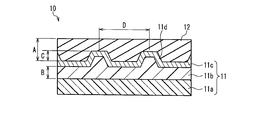
- FIG. 1 is a schematic cross-sectional view showing an example of an electrode used in the nonaqueous electrolyte battery of the present invention.
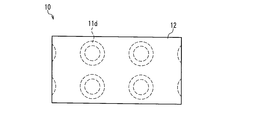
- FIG. 2 is a schematic plan view of FIG.
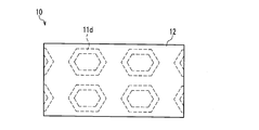
- FIG. 3 is a schematic plan view showing another example of an electrode used in the nonaqueous electrolyte battery of the present invention.
- FIG. 4 is a schematic plan view showing still another example of an electrode used in the nonaqueous electrolyte battery of the present invention.
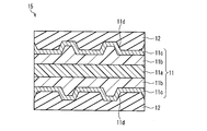
- FIG. 5 is a schematic cross-sectional view showing another example of an electrode used in the nonaqueous electrolyte battery of the present invention.
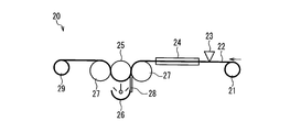
- FIG. 6 is a schematic side view showing an example of an electrode manufacturing apparatus and its manufacturing process used in the present invention.
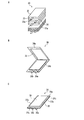
- FIG. 7A is a perspective view for explaining an electrode body used in the present invention
- FIG. 7B is a perspective view showing a state in which the electrode body is housed in an exterior material
- FIG. 7C is a view in which the electrode body is housed in an exterior material.
- the nonaqueous electrolyte battery of the present invention includes a positive electrode, a negative electrode, a separator, and a nonaqueous electrolyte.
- the positive electrode and the negative electrode each include a current collector and an active material-containing layer formed on the current collector, and the current collector is formed on at least one surface of the base material and the base material.
- a conductive layer is provided, and a resin layer is included between the base material and the conductive layer, and the active material-containing layer is formed on the conductive layer.
- the interface between the active material-containing layer and the conductive layer has irregularities in the thickness direction of the active material-containing layer, and the maximum height difference of the irregularities in the thickness direction of the active material-containing layer is as described above. It is set to 0.3 to 0.8 times the maximum thickness of the active material-containing layer.
- the interface between the active material-containing layer and the conductive layer has irregularities in the thickness direction of the active material-containing layer, the adhesion area between the current collector and the active material-containing layer increases, and the current collector The adhesion between the body and the active material-containing layer can be improved.
- a nonaqueous electrolyte battery with a high charge / discharge characteristic can be provided over a long period of time.
- the maximum height difference of the unevenness is less than 0.3 times the maximum thickness of the active material-containing layer, the height difference of the unevenness becomes too small, increasing the adhesion area between the current collector and the active material-containing layer. It is difficult to improve the adhesion between the current collector and the active material-containing layer.
- the maximum height difference of the unevenness exceeds 0.8 times the maximum thickness of the active material-containing layer, the height difference of the unevenness becomes too large, and the active material-containing layer is formed on the conductive layer.
- the active material is less likely to enter the concave and convex portions, and a gap is generated between the conductive layer and the active material-containing layer, thereby reducing the current collection efficiency of the current collector.
- the resin layer is preferably made of a radiation curable resin. This is because it is easy to perform uneven processing on the resin layer because the unevenness processing can be performed on the resin before curing, and then the resin can be cured.
- the maximum thickness of the active material-containing layer is preferably 30 ⁇ m or more and 200 ⁇ m or less, and more preferably 100 ⁇ m or more and 170 ⁇ m or less.
- the maximum thickness of the active material-containing layer is less than 30 ⁇ m, the active material-containing layer tends to be too thin and energy efficiency tends to decrease.
- the maximum thickness is more than 200 ⁇ m, the active material-containing layer becomes too thick, and the electrolyte is not active. It tends to be difficult to penetrate into the substance-containing layer.
- the thickness of the conductive layer is preferably 100 nm or more and 3 ⁇ m or less. If it is less than 100 nm, the electrical resistance as a current collector increases, and the current collection effect tends to decrease. On the other hand, if the thickness exceeds 3 ⁇ m, the stress of the conductive layer increases, and the current collector may be warped or undulated, making it difficult to use it as a current collector.
- the thickness of the substrate is preferably 3 ⁇ m or more and 20 ⁇ m or less, and more preferably 4.5 ⁇ m or more and 10 ⁇ m or less. If it is less than 3 ⁇ m, it is too thin to make it difficult to process the substrate, and it tends to be difficult to ensure the strength of the substrate. On the other hand, when the thickness exceeds 20 ⁇ m, the volume occupied by the base material increases. In the case of a battery having the same volume, the volume of the active material-containing layer decreases by the volume increase of the base material.
- a resin film As the substrate, a resin film, a metal foil such as a copper foil or an aluminum foil can be used, and a resin film is particularly preferable. It is because an electrode can be reduced in weight by using a resin film as a base material of a collector.
- FIGS. 1 to 5 the same parts are denoted by the same reference numerals, and redundant description is omitted.
- FIG. 1 is a schematic cross-sectional view showing an example of an electrode used in the nonaqueous electrolyte battery of the present invention.
- FIG. 2 is a schematic plan view of FIG.
- an electrode (positive electrode or negative electrode) 10 includes a current collector 11 and an active material-containing layer 12 formed on one surface of the current collector 11.
- the current collector 11 includes a base material 11a, a resin layer 11b provided on one side of the base material 11a, and a conductive layer 11c provided on the resin layer 11b.
- the layer 11c is electrically joined.
- the interface between the active material-containing layer 12 and the conductive layer 11 c includes unevenness 11 d in the thickness direction of the active material-containing layer 12.
- the maximum thickness A of the active material-containing layer 12 is set to 30 ⁇ m or more and 200 ⁇ m or less. Further, the maximum height difference C of the unevenness 11 d in the thickness direction of the active material-containing layer 12 is set to be not less than 0.3 times and not more than 0.8 times the maximum thickness A of the active material-containing layer 12. That is, a relationship of 0.3 ⁇ C / A ⁇ 0.8 is set. Further, the thickness B of the resin layer 11b is not particularly limited, but may be set to the same level as the maximum height difference C of the unevenness 11d, that is, about 0.3 ⁇ B / A ⁇ 0.8.
- the size of the pitch D of the unevenness 11d is about 50 ⁇ m. As shown in FIG. 2, the size of the pitch D may be different between left and right and up and down, or may be the same.
- the substrate 11a for example, a resin film made of one kind of resin selected from the group consisting of polyethylene terephthalate (PET), polyethylene naphthalate (PEN), aramid, polyethylene, polypropylene, polystyrene, polyamide and polyimide is used. Can do.
- the base material 11a it is good also as a conductive resin film by mixing a conductive filler etc. with the said resin.
- a metal foil such as a copper foil or an aluminum foil may be used as described above, the thickness of the base material 11a is set to 3 ⁇ m or more and 20 ⁇ m or less.
- the resin layer 11b is preferably formed from a radiation curable resin.
- the radiation curable resin is not particularly limited, but a bifunctional or higher radiation curable resin having good curability is preferable.
- acrylic acid, acrylic acid ester, acrylamide, methacrylic acid ester, methacrylic acid amide, allyl compound, vinyl ether, vinyl ester and the like can be used. These resins can be used alone or in combination.
- an electron beam, ultraviolet light, visible light, or the like can be used, but ultraviolet light is preferable because it can be irradiated with high energy at low cost.
- the conductive layer 11c As a material constituting the conductive layer 11c, for example, a metal such as aluminum or copper, or a carbon material such as graphite can be used.
- the method for forming the conductive layer 11c on the resin layer 11b is not limited, for example, a vacuum deposition method, a sputtering method, a plating method, or the like can be used.
- the thickness of the conductive layer 11c is set to 100 nm or more and 3 ⁇ m or less.
- the active material-containing layer 12 is formed of an active material, a conductive aid, a binder, and the like. As described above, the thickness of the active material-containing layer 12 is set to 30 ⁇ m or more and 200 ⁇ m or less.
- the cross section of the concave portion of the concave and convex portion 11 d is preferably a tapered shape that spreads upward from the viewpoint of filling of the active material.
- the bottom surface of the concave portion of the unevenness 11 d is flat, but is not limited to a flat shape, and may be a curved surface, for example.
- the planar shape of the unevenness 11 d is circular, but is not limited to a circular shape, and may be, for example, a rectangular shape as shown in FIG. 3 or a polygonal shape as shown in FIG. 4.
- planar shape of the unevenness 11d is not limited to the island shape shown in FIGS. 2 to 4, and may be a continuous groove shape that traverses both ends of the current collector 11.
- FIG. 5 is a schematic cross-sectional view showing another example of an electrode used in the nonaqueous electrolyte battery of the present invention.
- the electrode 15 is the same as that shown in FIG. 1 except that the resin layer 11b and the conductive layer 11c are provided on both surfaces of the base material 11a, and the active material-containing layer 12 is formed on each conductive layer 11c.
- the configuration is the same as the electrode 10 shown.
- the non-aqueous electrolyte battery using the electrode shown in FIG. 5 can exhibit the same effect as the non-aqueous electrolyte battery using the electrode shown in FIG.
- FIG. 6 is a schematic side view showing an example of an electrode manufacturing apparatus and its manufacturing process used in the present invention.
- the electrode manufacturing apparatus 20 in FIG. 6 includes a delivery roll 21 for delivering the base material 22, a coater 23 for applying a resin layer forming paint containing a radiation curable resin and a solvent onto the base material 22, Dryer 24 for removing the solvent contained in the resin layer-forming coating, embossing roll 25 having a concavo-convex processed surface for pressing the resin layer-forming coating layer after application, and radiation curing A radiation irradiation device 26 for irradiating and curing a resin layer-forming coating layer made of a functional resin, and a backup roll 27 for pressing the resin layer-forming coating layer and the substrate 22 in cooperation with the embossing roll 25 And a take-up roll 29 for taking up the base material 22.
- a delivery roll 21 for delivering the base material 22
- a coater 23 for applying a resin layer forming paint containing a radiation curable resin and a
- the base material 22 is fed out from the feed roll 21.
- a coating material for forming a resin layer containing a radiation curable resin and a solvent is applied onto the substrate 22 by the coater 23.
- the resin layer forming coating applied on the substrate 22 is dried by a dryer 24 to remove excess solvent.
- the resin layer forming coating material does not contain a solvent, the above drying is not necessary.
- the base material 22 is pressed against the embossing roll 25 from the back side of the base material 22 provided with the resin layer forming paint layer by the backup roll 27, so that the resin layer Concavities and convexities are formed on the surface of the forming coating layer, and radiation is applied to the coating layer for forming the resin layer through the base material 22 by the radiation irradiation device 26 in the abutted state.
- the shielding plate 28 prevents radiation from being applied to the resin layer-forming coating layer before the unevenness.
- the obtained base material with a resin layer is further wound between a backup roll 27 and an embossing roll 25 and wound around a winding roll 29.
- a conductive layer is formed on the surface of the uneven resin layer by sputtering or the like (not shown).
- the formed conductive layer reflects the unevenness of the lower resin layer, and the surface of the conductive layer is also formed uneven.
- an electrode used in the present invention shown in FIG. 1 is obtained by applying an active material-containing paint on the conductive layer and drying it by a normal method (not shown).
- the resin layer-forming coating layer is not cured until radiation irradiation and is in a flexible state, it is easy to be uneven when pressed against the embossing roll 25, and is in contact with the embossing roll 25 by radiation irradiation. In order to cure, the resin layer can be released from the embossing roll 25.
- the embossing roll 25 and the backup roll 27 may have a cooling function as necessary. Further, the backup roll 27 is not always necessary, and the pressing force may be controlled by controlling the traveling tension of the base material 22.
- FIG. 7A is a perspective view for explaining an electrode body used in the present embodiment
- FIG. 7B is a perspective view showing a state in which the electrode body is housed in an exterior material
- FIG. 7C is an electrode body as an exterior material. It is a perspective view of the stored state.
- the electrode body 30 is manufactured by laminating a rectangular positive electrode 31 and a rectangular negative electrode 32 with a rectangular separator 33 interposed therebetween.
- a positive electrode lead terminal 31 a is provided at one end of the positive electrode 31, and a negative electrode lead terminal 32 a is provided at one end of the negative electrode 32.
- a rectangular-shaped exterior material 34 having flexibility is folded into a valley and is composed of a first exterior surface 34a and a second exterior surface 34b.
- An electrode housing portion 35 is formed on the first exterior surface 34a by deep drawing.
- Each positive electrode lead terminal 31a (FIG. 7A) and each negative electrode lead terminal 32a (FIG. 7A) are overlapped and welded to form a positive electrode lead terminal portion 36a and a negative electrode lead terminal portion 36b, respectively.
- the electrode body 30 is housed in an electrode housing portion 35 formed by a first exterior surface 34a and a second exterior surface 34b that are folded together with a nonaqueous electrolyte. Further, among the outer periphery of the exterior member 34, three sides other than the one side that is valley-folded are joined with a predetermined width to form the sealing portions 37a, 37b, and 37c. The positive electrode lead terminal portion 36 a and the negative electrode lead terminal portion 36 b are drawn out from the sealing portion 37 c facing one side of the exterior material 34 that is folded down.
- the positive electrode 31 is a mixture of a positive electrode active material, a positive electrode conductive additive, a positive electrode binder, and the like, and a positive electrode mixture paste obtained by sufficiently kneading the mixture with a solvent. After coating and drying, the positive electrode mixture layer (positive electrode active material-containing layer) can be formed by controlling it to a predetermined thickness and a predetermined electrode density.
- a lithium manganese composite oxide having a spinel structure having a composition of the general formula LiMn 2 O 4 (a part of the constituent elements is replaced by an element such as Ge, Zr, Mg, Ni, Al, Co)
- a lithium cobalt composite oxide having a composition of the general formula LiCoO 2 ( a composite in which some of the constituent elements are substituted with elements such as Ni, Al, Mg, Zr, Ti, and B)
- a lithium nickel composite oxide having a composition of the general formula LiNiO 2 (a composite oxide in which a part of the constituent elements is substituted with an element such as Co, Al, Mg, Zr, Ti, B, etc.)
- composite oxide of a layered structure such as, lithium-containing composite oxide of olivine structure having a composition of general formula LiMPO 4 (where, M is at least one selected from Ni, Co and Fe).
- the positive electrode conductive auxiliary agent may be added as necessary for the purpose of improving the electric conductivity of the positive electrode mixture layer.
- the conductive powder used as the conductive auxiliary agent include carbon black, ketjen black, and acetylene black. Carbon powder such as fibrous carbon and graphite, and metal powder such as nickel powder can be used.
- Examples of the positive electrode binder include, but are not limited to, polyvinylidene fluoride (PVDF) and polytetrafluoroethylene (PTFE).
- PVDF polyvinylidene fluoride
- PTFE polytetrafluoroethylene
- the positive electrode current collector has the same structure as the current collector 11 shown in FIG. 5 described above.
- a PET film is used as the base material 11a
- an acrylic ultraviolet curable resin is used as the resin layer 11b
- the conductive material is conductive.
- a layer using an aluminum layer is used as the layer 11c.
- N-methyl-2-pyrrolidone for example, N-methyl-2-pyrrolidone or the like can be used.
- the negative electrode 32 is obtained by using a negative electrode mixture paste obtained by sufficiently kneading a mixture containing a negative electrode active material, a negative electrode conductive additive, a negative electrode binder, and the like, with both sides of the negative electrode current collector according to the present invention. After coating and drying, the negative electrode mixture layer (negative electrode active material-containing layer) can be formed by controlling it to a predetermined thickness and a predetermined electrode density.
- Examples of the negative electrode active material include carbon materials such as natural graphite or artificial graphite such as massive graphite, flaky graphite, and earthy graphite, but are not limited thereto as long as lithium ions can be occluded / released. .
- the negative electrode current collector has the same structure as that of the current collector 11 shown in FIG. 5 described above.
- a PET film is used as the base material 11a and an acrylic ultraviolet curable resin is used as the resin layer 11b.
- a layer using a copper layer is used as the layer 11c.
- the negative electrode conductive additive As the negative electrode conductive additive, the negative electrode binder, and the solvent, the same materials as those used for the positive electrode can be used.
- separator 33 it is preferable to use a separator having a two-layer structure including a heat-resistant porous substrate having a thickness of 10 to 50 ⁇ m and a microporous film made of a thermoplastic resin having a thickness of 10 to 30 ⁇ m.
- the heat-resistant porous substrate may be formed of, for example, a fibrous material having a heat-resistant temperature of 150 ° C. or higher, and the fibrous material may be cellulose or a modified product thereof, polyolefin, polyester, polyacrylonitrile, aramid, polyamide. It can be formed of at least one material selected from the group consisting of imides and polyimides. More specifically, sheet-like materials such as woven fabrics and nonwoven fabrics (including paper) made of the above materials can be used as heat-resistant porous materials. It can be used as a quality substrate.
- the microporous film made of the above thermoplastic resin has a melting point of, for example, 80 to 80, in order to provide the separator with a shutdown function that melts at a certain temperature or higher (100 to 140 ° C.) to close the micropores and increase the resistance.
- a microporous film made of a thermoplastic resin at 140 ° C. can be used.
- a microporous sheet made of an olefin polymer such as polypropylene and polyethylene having resistance to organic solvents and hydrophobicity can be used.
- an inorganic filler may be included in the heat-resistant porous substrate, and an inorganic filler layer having a thickness of about 3 to 10 ⁇ m is provided on the microporous film. May be.
- the inorganic filler for example, particles of at least one inorganic oxide selected from the group consisting of alumina, silica, titanium oxide, zirconium oxide, and boehmite can be used.
- the thickness of the separator 33 is not particularly limited, but is usually 25 to 90 ⁇ m.
- a laminated film in which a metal layer such as aluminum and a thermoplastic resin layer are laminated can be used.
- a laminate film in which a thermoplastic resin layer having a thickness of 20 to 50 ⁇ m is provided outside an aluminum layer having a thickness of 20 to 100 ⁇ m and an adhesive layer having a thickness of 20 to 100 ⁇ m is provided on the inside can be used. Thereby, sealing part 37a, 37b, 37c can be joined reliably by heat welding.
- the thickness of the exterior material 34 is not particularly limited, but is usually 60 to 250 ⁇ m.
- non-aqueous electrolyte a solution (non-aqueous electrolyte) in which a lithium salt is dissolved in an organic solvent is used.
- organic solvent examples include vinylene carbonate (VC), propylene carbonate (PC), ethylene carbonate (EC), butylene carbonate (BC), dimethyl carbonate (DMC), diethyl carbonate (DEC), and methyl ethyl carbonate (MEC).
- VC vinylene carbonate
- PC propylene carbonate
- EC ethylene carbonate
- BC butylene carbonate
- DMC dimethyl carbonate
- DEC diethyl carbonate
- MEC methyl ethyl carbonate
- the lithium salt for example, it can be used at least one lithium salt selected from LiClO 4, LiPF 6, LiBF 4 , LiAsF 6, LiSbF 6, LiCF 3 SO 3 and the like.
- the concentration of Li ions in the nonaqueous electrolytic solution may be 0.5 to 1.5 mol / L.
- non-aqueous electrolyte battery an example using a laminated electrode body in which rectangular electrodes are stacked via a separator is shown.
- a wound electrode body in which a long electrode is wound via a separator. May be used.
- Example 1 Preparation of current collector> The current collector used for the positive electrode and the negative electrode was produced as follows.
- a coating material for forming a resin layer was applied on a substrate with an extrusion coater and dried, and then a substrate with a single-sided resin layer was prepared by performing an unevenness treatment. .
- an acrylic ultraviolet curable coating material “Seika Beam EXF-01B” (trade name, viscosity: 130 mPa ⁇ s) manufactured by Dainichi Seika Co., Ltd. is diluted with methyl ethyl ketone to a solid content concentration of 60% by weight. It was prepared as follows.
- PET polyethylene terephthalate
- Limirror trade name, thickness: 6 ⁇ m
- the resin layer after the curing treatment was applied so that the thickness B (the thickness B of the resin layer 11b in FIG. 1) was about 50 ⁇ m.
- the diameter of the embossing roll was 170 mm, the maximum height difference of the unevenness was 55 ⁇ m, the unevenness pitch was 400 ⁇ m on both the left and right and top and bottom, and the planar shape of the unevenness was circular.
- Each of the backup rolls 27 had a diameter of 80 mm. Pressurization with a backup roll was performed at room temperature at 20 kN / m.
- the coater used was “Microgravure” (trade name) manufactured by Yasui Seiki Co., Ltd.
- the drying temperature in the dryer was 100 ° C., and the drying time was 30 seconds.
- the ultraviolet irradiation by the radiation irradiation apparatus was performed under the condition of irradiation amount: 360 mJ / cm 2 . The amount of ultraviolet irradiation was measured with a UV meter manufactured by Eye Graphics.
- the contact time of the substrate to the embossing roll was 6 seconds.
- a resin layer having irregularities on the surface was formed in the same manner as described above to prepare a substrate with a double-sided resin layer.
- the thickness B (B in FIG. 1) of the base material with the double-sided resin layer was measured at five points using a micrometer manufactured by Mitutoyo Corporation, and the average value was determined to be 49.5 ⁇ m. Was defined as a resin layer thickness B.
- the base material with the double-sided resin layer is set on the unwinding part of the vacuum evaporation apparatus, and after reducing the pressure to 1.5 ⁇ 10 ⁇ 3 Pa, the base material is transported through a cooling drum at ⁇ 20 ° C.
- the vehicle was run at 60 m / min and a conveyance tension of 100 N / m.
- aluminum having a purity of 99.99% by weight was evaporated by heating with an electron beam (output 5.1 kW), aluminum was deposited on the surface of the base material to form an aluminum thin film, and the base material was wound up.
- the thickness of the aluminum thin film was about 150 nm.
- the maximum height difference of the unevenness of the embossing roll is 55 ⁇ m, and the transfer rate of the unevenness becomes about 90% due to the curing shrinkage of the resin. Therefore, the maximum height difference C (C in FIG. 1) The maximum height difference C of the unevenness was actually measured and found to be 50 ⁇ m.
- a nonaqueous electrolyte battery was produced using the current collector produced above as follows.
- a positive electrode active material-containing paste was prepared. The paste is applied to both sides of the positive electrode current collector, dried to form a positive electrode active material-containing layer, and pressure-molded with a roller to obtain the maximum thickness A of the positive electrode active material-containing layer (A in FIG. 1).
- the electrode-coated surface was cut so as to have a width of 40 mm and a length of 72 mm to produce a positive electrode.
- the positive electrode lead terminal was formed in the one end part of the positive electrode in which the positive electrode active material content layer was not formed.
- A) was adjusted to 120 ⁇ m, and the negative electrode was prepared by cutting so that the electrode application surface had a width of 42 mm and a length of 74 mm. Moreover, the negative electrode lead terminal was formed in the one end part of the negative electrode in which the negative electrode active material content layer was not formed.
- a porous laminated film was prepared by laminating a porous film in which a boehmite particle layer having a thickness of 5 ⁇ m was formed on a microporous film made of polyethylene having a thickness of 16 ⁇ m and a nonwoven fabric made of polyethylene terephthalate having a thickness of 20 ⁇ m.
- the total thickness of the porous laminated film (separator) was about 20 ⁇ m, and the opening ratio was 50%.
- the separator is disposed between the positive electrode and the negative electrode so that the nonwoven fabric is in contact with the positive electrode, and each positive electrode and each negative electrode are laminated.
- each positive electrode lead terminal was welded to form a negative electrode lead terminal portion, and then inserted into an outer packaging material made of a laminate film.
- a solution obtained by dissolving LiPF 6 at a ratio of 1.2 mol / L in a solvent in which ethylene carbonate and diethyl carbonate were mixed at a volume ratio of 1: 2 in a non-aqueous electrolyte was injected into the exterior material. After that, the opening was sealed to produce a nonaqueous electrolyte battery.
- Example 2 A non-aqueous electrolyte battery was produced in the same manner as in Example 1 except that the current collector was used with a resin layer thickness B of 89.5 ⁇ m and a maximum unevenness C of the surface of the current collector of 90 ⁇ m. did.
- Example 3 A nonaqueous electrolyte battery was fabricated in the same manner as in Example 1 except that an electrode having a maximum thickness A of the active material-containing layer of 160 ⁇ m was used.
- a PET film “Lumirror” (trade name, thickness: 6 ⁇ m) manufactured by Toray Industries, Inc. is set in the unwinding part of the vacuum evaporation apparatus, and after reducing the pressure to 1.5 ⁇ 10 ⁇ 3 Pa, a cooling drum at ⁇ 20 ° C.
- the film was run at a conveyance speed of 60 m / min and a conveyance tension of 100 N / m.
- aluminum having a purity of 99.99% by weight was evaporated by heating with an electron beam (output 5.1 kW), aluminum was deposited on the surface of the film to form an aluminum thin film, and the film was wound up.
- the thickness of the aluminum thin film was about 150 nm.
- a nonaqueous electrolyte battery was produced in the same manner as in Example 1 except that the positive electrode current collector and the negative electrode current collector were used.
- Example 2 The nonaqueous electrolyte battery is the same as in Example 1 except that the current collector is used with the thickness B of the resin layer set to 0.4 ⁇ m and the maximum height difference C of the irregularities on the surface of the current collector set to 0.9 ⁇ m. Was made.
- the discharge capacity was less than 90% with respect to the discharge capacity of the first cycle at the 505th to 520th cycles, and the discharge of the first cycle was performed at the 700th to 730th cycles of the battery of Comparative Example 2.
- the number of cycles in which the discharge capacity was less than 90% of the capacity and the discharge capacity was less than 90% was defined as the life cycle number.
- Table 1 the ratio of the thickness B of the resin layer to the maximum thickness A of the active material-containing layer is represented by B / A, and the ratio of the maximum height difference C of the unevenness to the maximum thickness A of the active material-containing layer is expressed as C / Represented by A.
- the present invention can provide a non-aqueous electrolyte battery having high charge / discharge characteristics over a long period of time, and can be widely used as a power source for portable devices such as mobile phones and notebook personal computers.
- Electrode 11 Current collector 11a Base material 11b Resin layer 11c Conductive layer 11d Concavity and convexity 12 Active material containing layer 15 Electrode 20 Electrode manufacturing device 21 Feed roll 22 Base material 23 Coater 24 Dryer 25 Embossing roll 26 Radiation irradiation device 27 Backup roll 28 Shielding plate 29 Winding roll 30 Electrode body 31 Positive electrode 31a Positive electrode lead terminal 32 Negative electrode 32a Negative electrode lead terminal 33 Separator 34 Exterior material 34a First exterior surface 34b Second exterior surface 35 Electrode storage portion 36a Positive electrode lead terminal portion 36b Negative electrode lead terminal portion 37a, 37b, 37c Sealing part
Landscapes
- Chemical & Material Sciences (AREA)
- Chemical Kinetics & Catalysis (AREA)
- Electrochemistry (AREA)
- General Chemical & Material Sciences (AREA)
- Engineering & Computer Science (AREA)
- Materials Engineering (AREA)
- Composite Materials (AREA)
- Secondary Cells (AREA)
- Battery Electrode And Active Subsutance (AREA)
- Cell Electrode Carriers And Collectors (AREA)
Abstract
La présente batterie à électrolyte non aqueux comporte une électrode positive, une électrode négative, un séparateur et un électrolyte non aqueux. La batterie à électrolyte non aqueux est caractérisée en ce que : l'électrode positive et l'électrode négative comprennent chacune un collecteur et une couche contenant du matériau actif qui est formée sur le collecteur ; le collecteur comprend une base et une couche conductrice qui est appliquée sur au moins une surface de la base ; une couche de résine est disposée entre la base et la couche conductrice ; la couche contenant du matériau actif est formée sur la couche conductrice ; l'interface entre la couche contenant du matériau actif et la couche conductrice a des évidements et des projections dans la direction de l'épaisseur de la couche contenant du matériau actif ; et la différence de hauteur maximum entre les évidements et projections dans la direction de l'épaisseur de la couche contenant du matériau actif est comprise entre 0,3 et 0,8 fois (inclus) l'épaisseur maximum de la couche contenant du matériau actif.
Priority Applications (2)
| Application Number | Priority Date | Filing Date | Title |
|---|---|---|---|
| JP2011554319A JPWO2012131972A1 (ja) | 2011-03-31 | 2011-03-31 | 非水電解質電池 |
| PCT/JP2011/058200 WO2012131972A1 (fr) | 2011-03-31 | 2011-03-31 | Batterie à électrolyte non aqueux |
Applications Claiming Priority (1)
| Application Number | Priority Date | Filing Date | Title |
|---|---|---|---|
| PCT/JP2011/058200 WO2012131972A1 (fr) | 2011-03-31 | 2011-03-31 | Batterie à électrolyte non aqueux |
Publications (1)
| Publication Number | Publication Date |
|---|---|
| WO2012131972A1 true WO2012131972A1 (fr) | 2012-10-04 |
Family
ID=46929793
Family Applications (1)
| Application Number | Title | Priority Date | Filing Date |
|---|---|---|---|
| PCT/JP2011/058200 Ceased WO2012131972A1 (fr) | 2011-03-31 | 2011-03-31 | Batterie à électrolyte non aqueux |
Country Status (2)
| Country | Link |
|---|---|
| JP (1) | JPWO2012131972A1 (fr) |
| WO (1) | WO2012131972A1 (fr) |
Cited By (3)
| Publication number | Priority date | Publication date | Assignee | Title |
|---|---|---|---|---|
| KR101826250B1 (ko) * | 2014-10-07 | 2018-02-06 | 주식회사 엘지화학 | 구조적 안정성이 향상된 집전체를 포함하는 이차전지용 전극 |
| CN108140877A (zh) * | 2016-07-06 | 2018-06-08 | 株式会社Lg化学 | 二次电池 |
| JP2018174146A (ja) * | 2018-06-26 | 2018-11-08 | マクセルホールディングス株式会社 | 非水電解質二次電池及びその製造方法 |
Citations (9)
| Publication number | Priority date | Publication date | Assignee | Title |
|---|---|---|---|---|
| JPH07201363A (ja) * | 1993-12-29 | 1995-08-04 | Tdk Corp | リチウム二次電池 |
| JPH08321325A (ja) * | 1995-05-24 | 1996-12-03 | Japan Storage Battery Co Ltd | リチウムイオン電池 |
| JP2000268826A (ja) * | 1999-03-19 | 2000-09-29 | Hitachi Cable Ltd | Liイオン電池の負極集電体用銅材およびLiイオン電池 |
| JP2001085016A (ja) * | 1999-09-09 | 2001-03-30 | Sony Corp | 非水電解質電池 |
| JP2003031224A (ja) * | 2001-04-10 | 2003-01-31 | Toyo Kohan Co Ltd | 二次電池用の軽量集電体 |
| JP2004527068A (ja) * | 2000-12-21 | 2004-09-02 | モルテック・コーポレーション | 電気化学電池のためのリチウム負極 |
| JP2004342519A (ja) * | 2003-05-16 | 2004-12-02 | M & G Eco Battery Institute Co Ltd | ペースト式薄型電極を用いた電池とその製造方法 |
| JP2004356082A (ja) * | 2003-05-27 | 2004-12-16 | Samsung Sdi Co Ltd | リチウム二次電池用負極、およびこれを用いたリチウム二次電池 |
| JP2010225393A (ja) * | 2009-03-23 | 2010-10-07 | Toyota Motor Corp | 電池の電極の製造方法、製造装置、および電池 |
-
2011
- 2011-03-31 WO PCT/JP2011/058200 patent/WO2012131972A1/fr not_active Ceased
- 2011-03-31 JP JP2011554319A patent/JPWO2012131972A1/ja active Pending
Patent Citations (9)
| Publication number | Priority date | Publication date | Assignee | Title |
|---|---|---|---|---|
| JPH07201363A (ja) * | 1993-12-29 | 1995-08-04 | Tdk Corp | リチウム二次電池 |
| JPH08321325A (ja) * | 1995-05-24 | 1996-12-03 | Japan Storage Battery Co Ltd | リチウムイオン電池 |
| JP2000268826A (ja) * | 1999-03-19 | 2000-09-29 | Hitachi Cable Ltd | Liイオン電池の負極集電体用銅材およびLiイオン電池 |
| JP2001085016A (ja) * | 1999-09-09 | 2001-03-30 | Sony Corp | 非水電解質電池 |
| JP2004527068A (ja) * | 2000-12-21 | 2004-09-02 | モルテック・コーポレーション | 電気化学電池のためのリチウム負極 |
| JP2003031224A (ja) * | 2001-04-10 | 2003-01-31 | Toyo Kohan Co Ltd | 二次電池用の軽量集電体 |
| JP2004342519A (ja) * | 2003-05-16 | 2004-12-02 | M & G Eco Battery Institute Co Ltd | ペースト式薄型電極を用いた電池とその製造方法 |
| JP2004356082A (ja) * | 2003-05-27 | 2004-12-16 | Samsung Sdi Co Ltd | リチウム二次電池用負極、およびこれを用いたリチウム二次電池 |
| JP2010225393A (ja) * | 2009-03-23 | 2010-10-07 | Toyota Motor Corp | 電池の電極の製造方法、製造装置、および電池 |
Cited By (6)
| Publication number | Priority date | Publication date | Assignee | Title |
|---|---|---|---|---|
| KR101826250B1 (ko) * | 2014-10-07 | 2018-02-06 | 주식회사 엘지화학 | 구조적 안정성이 향상된 집전체를 포함하는 이차전지용 전극 |
| CN108140877A (zh) * | 2016-07-06 | 2018-06-08 | 株式会社Lg化学 | 二次电池 |
| US20180316021A1 (en) * | 2016-07-06 | 2018-11-01 | Lg Chem, Ltd. | Secondary battery |
| US10749185B2 (en) * | 2016-07-06 | 2020-08-18 | Lg Chem, Ltd. | Secondary battery |
| CN108140877B (zh) * | 2016-07-06 | 2021-02-02 | 株式会社Lg化学 | 二次电池 |
| JP2018174146A (ja) * | 2018-06-26 | 2018-11-08 | マクセルホールディングス株式会社 | 非水電解質二次電池及びその製造方法 |
Also Published As
| Publication number | Publication date |
|---|---|
| JPWO2012131972A1 (ja) | 2014-07-24 |
Similar Documents
| Publication | Publication Date | Title |
|---|---|---|
| CN105283999B (zh) | 二次电池和电极制造方法 | |
| US10217988B2 (en) | Secondary battery | |
| CN105074967B (zh) | 用于制造较厚电极的多层电池电极设计 | |
| CN103918104B (zh) | 带耐热绝缘层的隔板 | |
| US20190237746A1 (en) | Secondary battery and method for manufacturing same | |
| CN104704658B (zh) | 非水电解质二次电池用正极活性物质、非水电解质二次电池用正极活性物质的制造方法及非水电解质二次电池 | |
| WO2012127561A1 (fr) | Batterie à électrolyte non aqueux | |
| JP7069612B2 (ja) | 積層電極体、蓄電素子及び積層電極体の製造方法 | |
| JP6038813B2 (ja) | 電極の製造方法及び非水電解質電池の製造方法 | |
| CN103843172B (zh) | 带耐热绝缘层的隔板 | |
| JP2011060560A (ja) | リチウムイオン二次電池用集電体 | |
| WO2015083389A1 (fr) | Batterie rechargeable au lithium-ion | |
| JP2022188177A (ja) | フィルム外装電池、組電池および前記フィルム外装電池の製造方法 | |
| JP7510749B2 (ja) | リチウムイオン電池の製造方法 | |
| CN104067423A (zh) | 电极的制造方法以及非水电解质电池的制造方法 | |
| US20240266602A1 (en) | Lithium polymer battery | |
| KR20160027364A (ko) | 이차전지용 전극조립체 | |
| WO2012131972A1 (fr) | Batterie à électrolyte non aqueux | |
| CN112753111A (zh) | 锂离子二次电池用电极、其制造方法以及锂离子二次电池 | |
| JP7127638B2 (ja) | 二次電池およびその製造方法 | |
| US20200006736A1 (en) | Method for producing laminated type battery | |
| JP2008226555A (ja) | 非水電解質電池 | |
| JP7035702B2 (ja) | リチウムイオン二次電池 | |
| JP2025030992A (ja) | リチウムイオン電池用電極の製造方法および製造装置 | |
| WO2025234324A1 (fr) | Électrode positive et batterie secondaire |
Legal Events
| Date | Code | Title | Description |
|---|---|---|---|
| ENP | Entry into the national phase |
Ref document number: 2011554319 Country of ref document: JP Kind code of ref document: A |
|
| 121 | Ep: the epo has been informed by wipo that ep was designated in this application |
Ref document number: 11862555 Country of ref document: EP Kind code of ref document: A1 |
|
| NENP | Non-entry into the national phase |
Ref country code: DE |
|
| 122 | Ep: pct application non-entry in european phase |
Ref document number: 11862555 Country of ref document: EP Kind code of ref document: A1 |