WO2012131998A1 - Broyeur - Google Patents
Broyeur Download PDFInfo
- Publication number
- WO2012131998A1 WO2012131998A1 PCT/JP2011/058296 JP2011058296W WO2012131998A1 WO 2012131998 A1 WO2012131998 A1 WO 2012131998A1 JP 2011058296 W JP2011058296 W JP 2011058296W WO 2012131998 A1 WO2012131998 A1 WO 2012131998A1
- Authority
- WO
- WIPO (PCT)
- Prior art keywords
- drum body
- partition plate
- ground
- plate
- friction plate
- Prior art date
- Legal status (The legal status is an assumption and is not a legal conclusion. Google has not performed a legal analysis and makes no representation as to the accuracy of the status listed.)
- Ceased
Links
Images


Classifications
-
- B—PERFORMING OPERATIONS; TRANSPORTING
- B02—CRUSHING, PULVERISING, OR DISINTEGRATING; PREPARATORY TREATMENT OF GRAIN FOR MILLING
- B02C—CRUSHING, PULVERISING, OR DISINTEGRATING IN GENERAL; MILLING GRAIN
- B02C17/00—Disintegrating by tumbling mills, i.e. mills having a container charged with the material to be disintegrated with or without special disintegrating members such as pebbles or balls
- B02C17/18—Details
-
- B—PERFORMING OPERATIONS; TRANSPORTING
- B02—CRUSHING, PULVERISING, OR DISINTEGRATING; PREPARATORY TREATMENT OF GRAIN FOR MILLING
- B02C—CRUSHING, PULVERISING, OR DISINTEGRATING IN GENERAL; MILLING GRAIN
- B02C17/00—Disintegrating by tumbling mills, i.e. mills having a container charged with the material to be disintegrated with or without special disintegrating members such as pebbles or balls
- B02C17/04—Disintegrating by tumbling mills, i.e. mills having a container charged with the material to be disintegrated with or without special disintegrating members such as pebbles or balls with unperforated container
- B02C17/06—Disintegrating by tumbling mills, i.e. mills having a container charged with the material to be disintegrated with or without special disintegrating members such as pebbles or balls with unperforated container with several compartments
- B02C17/07—Disintegrating by tumbling mills, i.e. mills having a container charged with the material to be disintegrated with or without special disintegrating members such as pebbles or balls with unperforated container with several compartments in radial arrangement
-
- B—PERFORMING OPERATIONS; TRANSPORTING
- B02—CRUSHING, PULVERISING, OR DISINTEGRATING; PREPARATORY TREATMENT OF GRAIN FOR MILLING
- B02C—CRUSHING, PULVERISING, OR DISINTEGRATING IN GENERAL; MILLING GRAIN
- B02C17/00—Disintegrating by tumbling mills, i.e. mills having a container charged with the material to be disintegrated with or without special disintegrating members such as pebbles or balls
- B02C17/16—Mills in which a fixed container houses stirring means tumbling the charge
-
- B—PERFORMING OPERATIONS; TRANSPORTING
- B02—CRUSHING, PULVERISING, OR DISINTEGRATING; PREPARATORY TREATMENT OF GRAIN FOR MILLING
- B02C—CRUSHING, PULVERISING, OR DISINTEGRATING IN GENERAL; MILLING GRAIN
- B02C17/00—Disintegrating by tumbling mills, i.e. mills having a container charged with the material to be disintegrated with or without special disintegrating members such as pebbles or balls
- B02C17/18—Details
- B02C17/182—Lids
-
- B—PERFORMING OPERATIONS; TRANSPORTING
- B02—CRUSHING, PULVERISING, OR DISINTEGRATING; PREPARATORY TREATMENT OF GRAIN FOR MILLING
- B02C—CRUSHING, PULVERISING, OR DISINTEGRATING IN GENERAL; MILLING GRAIN
- B02C17/00—Disintegrating by tumbling mills, i.e. mills having a container charged with the material to be disintegrated with or without special disintegrating members such as pebbles or balls
- B02C17/18—Details
- B02C17/22—Lining for containers
-
- E—FIXED CONSTRUCTIONS
- E01—CONSTRUCTION OF ROADS, RAILWAYS, OR BRIDGES
- E01C—CONSTRUCTION OF, OR SURFACES FOR, ROADS, SPORTS GROUNDS, OR THE LIKE; MACHINES OR AUXILIARY TOOLS FOR CONSTRUCTION OR REPAIR
- E01C19/00—Machines, tools or auxiliary devices for preparing or distributing paving materials, for working the placed materials, or for forming, consolidating, or finishing the paving
- E01C19/02—Machines, tools or auxiliary devices for preparing or distributing paving materials, for working the placed materials, or for forming, consolidating, or finishing the paving for preparing the materials
- E01C19/05—Crushing, pulverising or disintegrating apparatus; Aggregate screening, cleaning, drying or heating apparatus; Dust-collecting arrangements specially adapted therefor
-
- B—PERFORMING OPERATIONS; TRANSPORTING
- B02—CRUSHING, PULVERISING, OR DISINTEGRATING; PREPARATORY TREATMENT OF GRAIN FOR MILLING
- B02C—CRUSHING, PULVERISING, OR DISINTEGRATING IN GENERAL; MILLING GRAIN
- B02C17/00—Disintegrating by tumbling mills, i.e. mills having a container charged with the material to be disintegrated with or without special disintegrating members such as pebbles or balls
- B02C17/16—Mills in which a fixed container houses stirring means tumbling the charge
- B02C2017/165—Mills in which a fixed container houses stirring means tumbling the charge with stirring means comprising more than one agitator
Definitions
- the present invention relates to a grinder for grinding aggregates and the like, and particularly relates to noise reduction measures.
- various ball mill type grinders exist as apparatuses for obtaining recycled aggregates from concrete and asphalt waste.
- many have a structure in which the drum body is partitioned by a plurality of partition plates in order to increase the residence time of the material to be ground.
- the material to be ground is partitioned. While moving from one end side of the drum body to the other end side through the gap between the peripheral edge of the plate and the drum body wall, the balls are ground by balls (grinding media) in each section.
- the present applicant has already proposed a grinding machine capable of preventing the above-mentioned phenomenon of co-rotation and greatly improving the grinding efficiency (the following patent document). 1 and 2).
- the inventions described in Patent Documents 1 and 2 it is possible to positively impart a back-and-forth motion to the grinding medium (ball or the like) by attaching the partition plate to the surface orthogonal to the central axis.
- the partition plate has a function as a stirring blade.
- the conventional ball mill type grinder including the grinders described in Patent Documents 1 and 2 has a problem of generating a large noise.
- the main cause of noise is the collision between the ball or the object to be ground and the drum body, and in particular, the volume of noise due to the collision between the ball and the drum body is high. Therefore, in order to effectively reduce the collision noise with the partition plate, for example, it is conceivable to reduce the number of grinding media. However, if the number of grinding media is reduced, the contact between the grinding object and the grinding media is possible. Since the number of times decreases, there arises a problem that the grinding efficiency decreases.
- the present invention has been made to solve the above-mentioned problems of the prior art, and reduces the noise by eliminating the grinding media without lowering the grinding efficiency, and hence the downsizing of the apparatus. It provides a grinder that can contribute to
- the grinding machine of the present invention comprises a cylindrical drum body configured to be able to discharge a ground material taken from a part from the other part, a central axis penetrating the drum body in the cylinder length direction, A plurality of partition plates that are attached at predetermined intervals in the axial direction of the central axis and divide the internal space of the drum body into a plurality of grinding chambers, and are attached to the drum body and face each of the partition plates.
- a plurality of friction plates, and at least one of the partition plate and the friction plate rotates. “At least one of the partition plate and the friction plate rotates” means that when only the partition plate rotates and the friction plate is stationary, only the friction plate rotates and the partition plate is stationary. The case where both the partition plate and the friction plate rotate.
- the grinding machine of one aspect of the present invention is characterized in that at least one of the friction plate and the partition plate is inclined with respect to a plane orthogonal to the central axis.
- the mill according to one aspect of the present invention is characterized in that a plurality of through holes through which the material to be ground can pass are provided in the partition plate.
- the grinder of one aspect of the present invention is characterized in that a plurality of through holes through which the material to be ground can pass are provided in the friction plate.
- the grinder according to one aspect of the present invention is characterized in that the partition plate and the friction plate rotate in opposite directions.
- the attritor of one embodiment of the present invention is characterized in that a concavo-convex pattern is formed on the surface of at least one of a friction plate and a partition plate.
- a concavo-convex pattern there are a fine concavo-convex pattern whose surface is finely roughened and a large concavo-convex pattern with relatively large convex portions and concave portions.
- a grinding machine includes a cylindrical drum body configured to be able to discharge a ground material taken from a part from another part, and a central shaft penetrating the drum body in the cylinder length direction.
- a plurality of partition plates attached at predetermined intervals in the axial direction of the central axis and partitioning the internal space of the drum body into a plurality of grinding chambers; and attached to the drum body, A plurality of friction plates facing each other, and at least one sieve member attached to the other part of the drum body and separating the material to be ground discharged from the drum body into a plurality of grades, At least one of the partition plate and the friction plate rotates. “At least one of the partition plate and the friction plate rotates” means that when only the partition plate rotates and the friction plate is stationary, only the friction plate rotates and the partition plate is stationary. The case where both the partition plate and the friction plate rotate.
- Another aspect of the grinding machine according to another aspect of the invention is characterized in that a plurality of conveyor members are provided for conveying the crushed materials separated by the sieve members for each of the grades.
- the present invention even if there is no friction medium such as a ball conventionally disposed in the drum body, it becomes possible to rub and grind the material to be ground between the partition plate and the friction plate. Therefore, the noise as a whole can be reduced by eliminating the noise that has conventionally occurred due to the collision between the grinding medium and the drum body. Furthermore, since the friction medium is unnecessary, the volume of the drum body can be reduced by the volume occupied by the friction medium.
- a narrow region in which the material to be ground is sandwiched between the friction plate and the partition plate can be easily produced, and grinding efficiency can be improved.
- the flow of the material to be ground is made smooth while maintaining high grinding efficiency. , Work efficiency can be improved.
- the distribution of the material to be ground is made smooth while maintaining high grinding efficiency. , Work efficiency can be improved.
- the grinding force applied to the material to be ground can be increased, and the grinding efficiency can be improved. it can.
- the present invention by forming a concavo-convex pattern on the surface of at least one of the partition plate and the friction plate, the number of places where the object to be ground is strongly rubbed against the partition plate or the friction plate is increased. Efficiency can be improved.
- the step of dividing the ground ground material into grades (sizes) according to the use by arranging a sieving member on the other part of the drum body from which the ground ground material is discharged can be carried out continuously with the grinding step, and the overall efficiency can be improved.
- a large container for storing the material to be ground separated according to the application is ground. Can be arranged without interference.
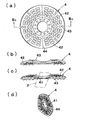
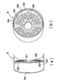
- FIG. 1 is a partial sectional front view of a grinder according to an embodiment of the present invention.
- the attritor according to the embodiment of the present invention is configured to be able to take a ground material (raw material) from a part (hopper (71)) into the inside and discharge it from the other part (discharge hopper (21)).
- the cylindrical drum body (1), the central axis (2) penetrating the drum body (1) in the cylinder length direction, and the drum body (1) are attached at predetermined intervals in the length direction of the central axis (2).
- a sieve member (22) that rotates together with the central shaft (2) is attached to the downstream side of the discharge hopper (21). Both ends of the central shaft (2) are supported by a pair of bearing members (16) and (17).
- a motor (M) serving as a drive source for rotating the central shaft (2) is connected to one end portion (upstream side) of the central shaft (2), and a sieve member (22) is connected to the multi-end portion (downstream side). Is attached.
- the sieving member (22) has a cylindrical shape having a taper that gradually becomes larger in diameter as it is separated from the drum body (1).
- the drum body (1) has a substantially cylindrical shape by combining two upper and lower semi-cylindrical members.
- the plurality of partition plates (4) are provided at regular intervals in the axial direction of the central axis, and divide the interior of the drum body (1) into a plurality of grinding chambers (6) in the axial length direction.
- Each partition plate (4) is inclined with respect to a plane orthogonal to the central axis (2) and is substantially parallel to each other.
- Each grinding chamber (6) has no grinding media (such as balls).
- the plurality of friction plates (5) are arranged in each grinding chamber (6) and are orthogonal to the central axis (2).
- the ground material (a) is supplied from the hopper (71) together with the water (b) and sequentially passes through each grinding chamber (6), and then the outermost part of the drum body (1). It is discharged from the discharge hopper (21) on the downstream side and sent to the sieving member (22).
- a dry structure in which the material to be ground (a) is sent by a blower may be adopted.
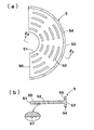
- FIG. 3A and 3B are diagrams showing the partition plate according to the present embodiment, in which FIG. 3A is a plan view, FIG. 3B is a side view, and FIG. 3C is a cross-sectional view taken along line IIIc-IIIc.
- the partition plate (4) has a substantially circular structure in which two semicircular curved plates are combined, and the central axis (2) is inserted through the central hole (41).
- the partition plate (4) is attached to be inclined clockwise from a plane orthogonal to the central axis (2). Even when the inclination direction of the partition plate (4) is opposite to that of the present embodiment, the material to be ground (a) is moved by water flow (in the case of a wet type) or air flow (in the case of a dry type).
- the partition plate (4) is provided with a plurality of partial arc-shaped through holes (42) arranged concentrically.
- the circular arc width of the through hole (42) is set to a size that allows only the object to be ground (a) ground to be less than a predetermined particle diameter.
- the arc width of the through hole (42) may gradually decrease from the upstream partition plate (4) of the drum body (1) toward the downstream partition plate (4).
- the surface of the partition plate (4) is provided with a hemispherical convex portion (43), and a large concave-convex pattern is formed. Due to the presence of such a large concavo-convex pattern, when the crushed object (a) collides with the partition plate (4) from an oblique direction, the surface of the partition plate (4) slips slightly, and then the convex portion (43). Thus, the grinding efficiency of the material to be ground (a) is increased.
- the convex part (43) of a partition plate (4) can be comprised with a especially hard material (for example, cemented carbide), the wear of a partition plate (4) can be reduced, and a lifetime can also be extended. In addition, it may replace with a convex part (43) and you may form the uneven
- the partition plate (4) is shown in a flat plate shape for easy viewing.
- the partition plate (4) in the present embodiment is spaced at regular intervals in the circumferential direction. It has a curved surface structure in which the peaks and valleys are repeated.
- the partition plate (4) may have a planar structure.
- the partition plate (4) as a whole may be an elliptical plate instead of a disc.
- FIG. 2A and 2B are diagrams showing the friction plate according to the present embodiment, in which FIG. 2A is a plan view and FIG. 2B is a cross-sectional view taken along the line IIb-IIb.
- the friction plate (5) is divided into two parts corresponding to the semi-cylindrical drum body (1).
- the friction plate (5) is divided into two parts, a semi-disc part (50) and a semi-disc part ( 50) and a flange portion (54) surrounding the outer peripheral side.
- a semicircular inner edge peripheral portion (51) is formed at a position corresponding to the center portion of the combination of the two friction plates (5), and the inner edge peripheral portion (51). Faces the central axis (2) with a predetermined gap.
- the friction plate (5) is attached to the drum body (1) with screws (not shown) in a state where the outer peripheral portion (53) of the semi-cylindrical flange portion (54) is in contact with the inner wall of the drum body (1). It is attached.
- the flange portion (54) is provided with a screw insertion hole (55).
- the display in the cross section of the friction plate (5) in FIG. 1 is omitted, but the semicircular plate portion (50) of the friction plate (5) has many partial circles arranged concentrically.
- An arc-shaped through hole (52) is formed.
- the circular arc width of the through hole (52) is set to a size that allows only the material to be ground (a) ground to be less than a predetermined particle size in the grinding chamber (6).
- the arc width of the through hole (52) may gradually decrease from the upstream friction plate (5) of the drum body (1) toward the downstream friction plate (5).
- the semicircular disk portion (50) and the flange portion (54) of the friction plate (5) are finely formed by casting, press molding or the like as shown in the partial enlarged view of FIG. An uneven pattern (57) is provided.
- the friction plate (5) in this embodiment has a flat plate structure, the friction plate (5) may have a curved plate structure like the modified example demonstrated later. Further, the friction plate (5) may be an elliptical plate instead of a circular plate as a whole.
- At least one of the partition plate (4) and the friction plate (5) may be rotated, but in this embodiment, the drum body (1) is fixed and the central shaft (2) is rotated. ing. Therefore, in the present embodiment, the central axis (2) rotates and the partition plate (4) attached to the central axis (2) rotates, while the friction plate (5) attached to the drum body (1) It is stationary.
- FIG. 6 is a cross-sectional view for explaining the grinding action by the friction plate and the partition plate.
- the partition plate (4) when the partition plate (4) is rotated by 180 ° from the solid line position shown in FIG. 6, the partition plate (4) is in the position shown by the broken line in FIG. .
- the ground material (a) is strongly pressed between the partition plate (4) and the friction plate (5). At the same time, it receives a frictional force due to the rotational force of the partition plate (4).
- the material to be ground (a) includes the through holes (42) and (52) of the partition plate (4) and the friction plate (5), and the clearance between the friction plate (5) and the central axis (2) (Sp1). It passes through the gap (Sp2) between the partition plate (4) and the drum body (1), and is sent to the downstream side together with water (b). At this time, since the action of scraping off the foreign matter can be obtained also by the edges of the numerous through holes (42) and (52) provided in the partition plate (4) and the friction plate (5), the foreign matter is more effectively removed. Can be removed.
- the structure of the attritor of the present invention is not limited to the structure shown in FIG.
- only the friction plate (5) may be rotated to fix the partition plate (4).
- the drum body (1) is rotated, but the drum medium (1), the partition plate (4), friction, and the like are caused by the centrifugal force that the grinding medium (a) receives from the rotation of the drum body (1).
- Even a strong collision with the plate (5) does not produce a loud noise like a collision between the drum body (1) and the grinding medium.
- a large centrifugal force can be applied to the material to be ground (a) by the rotation of the drum body (1), the collision between the material to be ground (a) and the flange portion (54) of the friction plate (5).
- Milling efficiency is increased. Moreover, you may rotate both a partition plate (4) and a friction plate (5) in a reverse direction relatively. In that case, since the frictional force which acts on the to-be-ground material (a) pinched
- FIG. 5 is a cross-sectional view showing a first modification of the friction plate (5).
- the flange portion (54) is provided wider than that shown in FIG. 2 (b), and extends to the middle point of each grinding chamber (6), for example. ing.
- the flange portion (54) wide, the area of the inner side surface of the flange portion (54) with which the object to be ground (a) collides increases, so that the grinding efficiency can be increased. .
- the fine uneven pattern (57) formed by sandblasting or the like on the surface of the semicircular plate portion (50) or the flange portion (54) of the friction plate (5). Is formed.
- the partition plate (4) may also be provided with a fine uneven pattern to further improve the grinding efficiency of the material to be ground (a).
- the friction plate 5 may be formed with a convex portion such as the partition plate 4 or a large concave-convex pattern with the concave portion ( (Refer to a modified example described later) Even in that case, the above-described effects can be obtained.
- the constituent materials of the partition plate (4) and the friction plate (5) are not limited, but include general-purpose steel materials, high-hardness steel materials such as alloy steels, cemented carbides, ceramics, metal-ceramic materials, and so on. In order to increase the grinding efficiency or extend the service life, a material with higher hardness is preferred. Only a part of the partition plate (4) and the friction plate (5) made of a general-purpose steel material may be made of a high-hardness material, for example, by coating the surface with a high-hardness material.
- FIG. 4 is a partial sectional front view of the sieving member and the conveyor device according to the present embodiment.
- a guide member (82) for receiving a relatively small-diameter ground material (a1) passing through the mesh of the sieving member (22), and a lower part of the guiding member (82) are arranged below the sieving member (22).
- a first feeding device (8) is arranged below the sieving member (22), a guide member (82) for receiving a relatively small-diameter ground material (a1) passing through the mesh of the sieving member (22), and a lower part of the guiding member (82) are arranged.
- a first feeding device (8) is arranged.
- a first conveyor member (81) for sending the material to be ground (a1) to the rear of the paper surface of FIG. 4 is attached to the first feeding device (9).
- a second feeding device (9) for receiving a relatively large-diameter ground material (a2) sent without passing through the mesh of the sieve member (22) is disposed on the downstream side of the sieve member
- a sieving member (22) is provided at the downstream end of the grinder, and the ground material to be ground is separated into sizes corresponding to the intended use, so that it is continuous with the grinding process.
- the mesh size of the sieving member (22) can be arbitrarily selected according to the type of aggregate to be finally obtained. For example, when separating into gravel and sand, for example, a mesh having a size of about 5 mm can be adopted.
- the material of the sieving member (22) is not particularly limited, but generally punched metal (steel plate) is used.
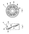
- FIG. 7A and 7B are diagrams showing a second modification of the friction plate, in which FIG. 7A is a perspective view of one piece, and FIG. 7B is a perspective view of a state in which the two pieces are combined.
- the friction plate (5) which concerns on a 2nd modification has the semicircular disk part (50) similar to the partition plate (4) shown in FIG. That is, the semicircular disk part (50) is formed of a curved surface inclined with respect to a plane orthogonal to the central axis (2), and the semicircular disk part (50) has a large number of convex parts (56 concentrically arranged).
- the circular arc width of the through hole (52) is set to a size that allows only the object to be ground (a) ground to be less than a predetermined particle diameter.
- the flange portion (54) is provided wide like the first modified example, and the friction plate (5) is in a state where the outer peripheral portion (53) of the flange portion (54) is in contact with the drum body (1). Is attached to the drum body (1).
- the partition plate (4) is orthogonal to the central axis (2).
- the partition plate (4) may have a planar structure or a curved surface structure, for example, a partition plate (4) having substantially the same shape as the semicircular plate portion (50) of the friction plate (5) shown in FIG. 2 can be used. .
- FIGS. 8A and 8B are views showing a third modification of the friction plate, in which FIG. 8A is a perspective view of one piece, and FIG. 8B is a perspective view of a state in which two pieces are combined.
- the friction plate (5) according to the third modification has a semicircular plate portion (50) orthogonal to the central axis (2).
- the semicircular disk portion (50) is provided with a large number of concentric convex portions (56) (concave / convex pattern) and a large number of concentric circular arc-shaped through holes (52).
- the inner periphery (51) faces the central axis (2) with a predetermined gap.
- the circular arc width of the through hole (52) is set to a size that allows only the material to be ground (a) ground to be less than a predetermined particle size.
- the flange portion (54) is provided wide like the first modified example, and the friction plate (5) is in a state where the outer peripheral portion (53) of the flange portion (54) is in contact with the drum body (1). Is attached to the drum body (1).
- the partition plate (4) is preferably inclined with respect to the central axis (2).
- the partition plate (4) may have a planar structure or a curved structure.
- FIGS. 9A and 9B are diagrams showing a fourth modification of the friction plate, where FIG. 9A is a perspective view of one piece, and FIG. 9B is a perspective view of a state in which two pieces are combined.
- the friction plate (5) according to the fourth modification has a semicircular plate portion (50) and a flange portion (54) having substantially the same shape as the friction plate (5) according to the second modification shown in FIG. Yes.
- the friction plate (5) according to the fourth modified example is different from the friction plate (5) according to the second modified example in that the semicircular plate portion (50) is inclined with respect to the plane orthogonal to the central axis (2). The direction of being is the opposite.
- the friction plate (5) according to the second modification is inclined clockwise from the plane orthogonal to the center axis (2)
- the friction plate (5) according to the fourth modification is the center axis (2 ) Tilted counterclockwise from the plane perpendicular to.
- the movement of the material to be ground (a) is a water flow (when wet) or an air flow (when dry). Therefore, there is no problem in the grinding process.
- a partition plate (4) is orthogonal to a central axis (2).
- the partition plate (4) may have a planar structure or a curved surface structure, for example, a partition plate (4) having substantially the same shape as the semicircular plate portion (50) of the friction plate (5) shown in FIG. 2 can be used. .
- the structures and materials of the partition plate (4) and the semicircular plate portion (50) of the friction plate (5) may be the same.
- whether the partition plate (4) and the semicircular plate portion (50) of the friction plate (5) are orthogonal to the central axis (2) or inclined from the orthogonal plane is adopted alternately. Or both may be inclined.
- both do not need to incline it is preferable that the narrow area
- FIG. 10 is a partial cross-sectional front view of a grinder according to a modification of the overall structure.
- the attritor according to this modification is provided with a hopper (71) for charging the material to be ground (raw material) at the center of the drum body (1), and on the left and right sides of the drum body (1), A discharge hopper (21), a sieve member (22), and a motor (M) are provided.
- a sieve rotary shaft (2a) separated from the central axis (2) is provided, and the central axis (2) and the sieve rotary shaft are provided.
- the motor (M) is connected to both end portions of the central shaft (2), and the left and right sieve members (22) are rotated together with the central shaft (2) by rotating the left and right motors (M) in synchronization. It is good also as a structure to make. In this case, the central axis (2) and the sieve rotation axis (2a) are integrated. According to the structure of this modified example, the raw material is introduced from the center of the drum body (1) and discharged from the left and right sieving members (22), so that the processing capacity can be greatly improved (about twice). it can.
- the mill according to the present invention is used for obtaining recycled aggregate from concrete waste or asphalt waste, for example.
Landscapes
- Engineering & Computer Science (AREA)
- Food Science & Technology (AREA)
- Architecture (AREA)
- Civil Engineering (AREA)
- Structural Engineering (AREA)
- Crushing And Grinding (AREA)
Abstract
La présente invention a trait à un broyeur qui est équipé : d'un corps de tambour tubulaire qui est configuré de manière à ce qu'une substance devant être broyée introduite au niveau d'une section puisse être évacuée à partir d'une autre section ; d'un arbre central qui pénètre à l'intérieur du corps de tambour dans la direction de la longueur du tuyau ; d'une pluralité de cloisons de séparation qui sont attachées à intervalle prédéterminé dans le sens de la longueur de l'arbre central et qui compartimentent l'espace intérieur du corps de tambour en une pluralité de chambres de broyage ; et d'une pluralité de plaques de frottement qui sont attachées au corps de tambour et qui font face aux cloisons de séparation. Les cloisons de séparation et/ou les plaques de frottement tournent.
Priority Applications (8)
| Application Number | Priority Date | Filing Date | Title |
|---|---|---|---|
| JP2013507003A JP5825646B2 (ja) | 2011-03-31 | 2011-03-31 | 摩砕機 |
| PCT/JP2011/058296 WO2012131998A1 (fr) | 2011-03-31 | 2011-03-31 | Broyeur |
| KR1020177008281A KR101850845B1 (ko) | 2011-03-31 | 2011-07-29 | 마쇄기 |
| KR1020137021152A KR101724432B1 (ko) | 2011-03-31 | 2011-07-29 | 마쇄기 |
| PCT/JP2011/067554 WO2012132041A1 (fr) | 2011-03-31 | 2011-07-29 | Broyeur |
| JP2011532424A JP4959857B1 (ja) | 2011-03-31 | 2011-07-29 | 摩砕機 |
| KR1020187010620A KR101944430B1 (ko) | 2011-03-31 | 2011-07-29 | 마쇄기 |
| US13/973,133 US9427742B2 (en) | 2011-03-31 | 2013-08-22 | Mill |
Applications Claiming Priority (1)
| Application Number | Priority Date | Filing Date | Title |
|---|---|---|---|
| PCT/JP2011/058296 WO2012131998A1 (fr) | 2011-03-31 | 2011-03-31 | Broyeur |
Publications (1)
| Publication Number | Publication Date |
|---|---|
| WO2012131998A1 true WO2012131998A1 (fr) | 2012-10-04 |
Family
ID=46929818
Family Applications (2)
| Application Number | Title | Priority Date | Filing Date |
|---|---|---|---|
| PCT/JP2011/058296 Ceased WO2012131998A1 (fr) | 2011-03-31 | 2011-03-31 | Broyeur |
| PCT/JP2011/067554 Ceased WO2012132041A1 (fr) | 2011-03-31 | 2011-07-29 | Broyeur |
Family Applications After (1)
| Application Number | Title | Priority Date | Filing Date |
|---|---|---|---|
| PCT/JP2011/067554 Ceased WO2012132041A1 (fr) | 2011-03-31 | 2011-07-29 | Broyeur |
Country Status (4)
| Country | Link |
|---|---|
| US (1) | US9427742B2 (fr) |
| JP (1) | JP5825646B2 (fr) |
| KR (3) | KR101850845B1 (fr) |
| WO (2) | WO2012131998A1 (fr) |
Cited By (3)
| Publication number | Priority date | Publication date | Assignee | Title |
|---|---|---|---|---|
| WO2014168479A1 (fr) * | 2013-04-08 | 2014-10-16 | Koninklijke Bam Groep N.V. | Procédé pour la production d'agrégats d'asphalte de récupération |
| US9427742B2 (en) | 2011-03-31 | 2016-08-30 | Daito Doboku, Ltd. | Mill |
| CN109580349A (zh) * | 2018-12-12 | 2019-04-05 | 中咨公路养护检测技术有限公司 | 一种沥青冷补混合料性能试验装置及试验方法 |
Families Citing this family (13)
| Publication number | Priority date | Publication date | Assignee | Title |
|---|---|---|---|---|
| DE102015101476A1 (de) * | 2015-02-02 | 2016-08-04 | Netzsch-Feinmahltechnik Gmbh | Rührwerkskugelmühle und mahlscheibe für rührwerkskugelmühlen |
| JP6096867B2 (ja) * | 2015-11-20 | 2017-03-15 | 有限会社大東土木 | コンクリートガラから高品質の再生骨材を製造する方法に適用する摩砕機 |
| US20170197217A1 (en) * | 2016-11-21 | 2017-07-13 | Thomas Bruggemann | Dual Purpose Female Cannabis Seedless Flower Bud Trimmers, Kief Separators and Methods |
| US20190168232A1 (en) * | 2016-11-21 | 2019-06-06 | Thomas Joseph Bruggemann | Multi-Purpose Plant Flower Trimmer and Separator |
| CA3050980C (fr) * | 2017-01-26 | 2023-10-03 | Outotec (Finland) Oy | Perfectionnements apportes a des broyeurs a billes agitees |
| CN111566904B (zh) | 2017-12-28 | 2023-04-28 | 株式会社电装 | 旋转电机 |
| DE112018006694T5 (de) | 2017-12-28 | 2020-09-10 | Denso Corporation | Rotierende elektrische Maschine |
| KR102205909B1 (ko) * | 2019-10-11 | 2021-01-20 | 박만선 | 해조 찌꺼기 처리장치 |
| CN113413972A (zh) * | 2021-05-19 | 2021-09-21 | 周小飞 | 一种三筒双向阶梯式球磨机 |
| CN113798019B (zh) * | 2021-09-16 | 2023-09-29 | 安徽开林新材料股份有限公司 | 一种钢铁表面修复剂生产用粉体碾磨筛粒装置 |
| CN115555099B (zh) * | 2022-09-28 | 2024-11-15 | 驻马店恒久新型耐磨材料有限公司 | 一种溢流球磨机衬板组件 |
| CN115591652B (zh) * | 2022-10-19 | 2025-05-13 | 米脂冀东水泥有限公司 | 一种用于水泥磨出料篦板的篦缝结构及使用方法 |
| CN119076137A (zh) * | 2024-09-02 | 2024-12-06 | 江西森能新材料科技有限公司 | 一种锂电池负极材料筛分装置 |
Citations (4)
| Publication number | Priority date | Publication date | Assignee | Title |
|---|---|---|---|---|
| JPH0466132A (ja) * | 1990-07-06 | 1992-03-02 | Daikin Ind Ltd | 粉体機械 |
| JP2003073153A (ja) * | 2001-09-03 | 2003-03-12 | Ube Ind Ltd | 焼却灰の処理方法 |
| JP2003190827A (ja) * | 2001-12-27 | 2003-07-08 | Daito Doboku:Kk | 再生骨材の製造方法 |
| JP2006205118A (ja) * | 2005-01-31 | 2006-08-10 | Daito Doboku:Kk | 摩砕機及び摩砕機用仕切板 |
Family Cites Families (22)
| Publication number | Priority date | Publication date | Assignee | Title |
|---|---|---|---|---|
| FR1315156A (fr) * | 1961-12-06 | 1963-01-18 | Machine à broyer et disperser des particules de matiere dans un liquide | |
| US3404846A (en) * | 1962-10-09 | 1968-10-08 | Nordberg Manufacturing Co | Autogenous grinding mill |
| GB1037350A (en) * | 1965-05-04 | 1966-07-27 | Smidth & Co As F L | Method of making a slurry and compartment mill for carrying out the method |
| US3441226A (en) * | 1965-07-19 | 1969-04-29 | Camillo Bargero | Cylindrical mill for grinding cement |
| GB1373285A (en) * | 1972-05-10 | 1974-11-06 | Smidth & Co As F L | Tube mills |
| GB1478426A (en) * | 1975-11-20 | 1977-06-29 | Smidth & Co As F L | Tube mills for drying and grinding |
| FI66441C (fi) * | 1983-02-01 | 1984-10-10 | Ahlstroem Oy | Anordning foer behandling av ett fibrigt material |
| US4498634A (en) * | 1983-09-01 | 1985-02-12 | Fuller Company | Division head for grinding mill |
| JPS6171846A (ja) * | 1984-09-17 | 1986-04-12 | 川崎重工業株式会社 | 磨砕物粒形調整装置 |
| EP0288565A4 (fr) * | 1986-10-21 | 1989-10-04 | Belgorodskij Ti Str Material | Broyeur tubulaire a bille. |
| HU200288B (en) * | 1986-11-14 | 1990-05-28 | Belgorodskij Ti Str Material | Deodorants, deodorant sheets, fi |
| EP0319579B1 (fr) * | 1987-01-23 | 1991-03-20 | Belgorodsky Tekhnologichesky Institut Stroitelnykh Materialov Imeni I.A.Grishmanova | Broyeur tubulaire a boulets |
| US5174512A (en) * | 1988-12-16 | 1992-12-29 | Snamprogetti S.P.A. | Grinding process and a continuous high-capacity micronizing mill for its implementation |
| CN1043014C (zh) * | 1990-11-13 | 1999-04-21 | 国家建筑材料工业局合肥水泥研究设计院 | 管磨机 |
| JPH0763643B2 (ja) * | 1991-03-29 | 1995-07-12 | 株式会社栗本鐵工所 | ボールミルの複合中仕切 |
| JP3261125B1 (ja) * | 2001-07-06 | 2002-02-25 | 有限会社大東土木 | 摩砕機 |
| AU2002352181A1 (en) * | 2001-11-29 | 2003-06-10 | Polysius Ag | Tube grinder and method for comminuting lumpy grinding stock |
| JP2005279593A (ja) * | 2004-03-30 | 2005-10-13 | Ohashi Hiroyuki | 破砕機における破砕物の粒度調整方法、破砕機及び破砕作業車 |
| JP3945717B1 (ja) | 2006-10-23 | 2007-07-18 | 有限会社大東土木 | 摩砕機及び摩砕機用仕切板 |
| JP2010125446A (ja) | 2008-12-01 | 2010-06-10 | Daito Doboku:Kk | 摩砕機 |
| JP4959857B1 (ja) * | 2011-03-31 | 2012-06-27 | 有限会社大東土木 | 摩砕機 |
| WO2012131998A1 (fr) | 2011-03-31 | 2012-10-04 | 有限会社大東土木 | Broyeur |
-
2011
- 2011-03-31 WO PCT/JP2011/058296 patent/WO2012131998A1/fr not_active Ceased
- 2011-03-31 JP JP2013507003A patent/JP5825646B2/ja active Active
- 2011-07-29 WO PCT/JP2011/067554 patent/WO2012132041A1/fr not_active Ceased
- 2011-07-29 KR KR1020177008281A patent/KR101850845B1/ko active Active
- 2011-07-29 KR KR1020137021152A patent/KR101724432B1/ko active Active
- 2011-07-29 KR KR1020187010620A patent/KR101944430B1/ko active Active
-
2013
- 2013-08-22 US US13/973,133 patent/US9427742B2/en active Active
Patent Citations (4)
| Publication number | Priority date | Publication date | Assignee | Title |
|---|---|---|---|---|
| JPH0466132A (ja) * | 1990-07-06 | 1992-03-02 | Daikin Ind Ltd | 粉体機械 |
| JP2003073153A (ja) * | 2001-09-03 | 2003-03-12 | Ube Ind Ltd | 焼却灰の処理方法 |
| JP2003190827A (ja) * | 2001-12-27 | 2003-07-08 | Daito Doboku:Kk | 再生骨材の製造方法 |
| JP2006205118A (ja) * | 2005-01-31 | 2006-08-10 | Daito Doboku:Kk | 摩砕機及び摩砕機用仕切板 |
Cited By (4)
| Publication number | Priority date | Publication date | Assignee | Title |
|---|---|---|---|---|
| US9427742B2 (en) | 2011-03-31 | 2016-08-30 | Daito Doboku, Ltd. | Mill |
| WO2014168479A1 (fr) * | 2013-04-08 | 2014-10-16 | Koninklijke Bam Groep N.V. | Procédé pour la production d'agrégats d'asphalte de récupération |
| NL2010588C2 (en) * | 2013-04-08 | 2014-10-16 | Konink Bam Groep Nv | Process for the production of reclaimed asphalt aggregates and use thereof in the production of an asphalt composition. |
| CN109580349A (zh) * | 2018-12-12 | 2019-04-05 | 中咨公路养护检测技术有限公司 | 一种沥青冷补混合料性能试验装置及试验方法 |
Also Published As
| Publication number | Publication date |
|---|---|
| US9427742B2 (en) | 2016-08-30 |
| JP5825646B2 (ja) | 2015-12-02 |
| WO2012132041A1 (fr) | 2012-10-04 |
| KR101850845B1 (ko) | 2018-04-20 |
| KR20180040742A (ko) | 2018-04-20 |
| KR101944430B1 (ko) | 2019-02-01 |
| JPWO2012131998A1 (ja) | 2014-07-24 |
| US20140008473A1 (en) | 2014-01-09 |
| KR20170037687A (ko) | 2017-04-04 |
| KR20140034141A (ko) | 2014-03-19 |
| KR101724432B1 (ko) | 2017-04-07 |
Similar Documents
| Publication | Publication Date | Title |
|---|---|---|
| JP5825646B2 (ja) | 摩砕機 | |
| JP6051280B2 (ja) | 摩砕機 | |
| JP5847206B2 (ja) | 再生骨材の製造方法及びこの方法により得られる再生骨材 | |
| JP2011045809A (ja) | 摩砕機 | |
| US8241095B2 (en) | Abrasion apparatus with an abrading belt and product chambers | |
| JP6598169B2 (ja) | 摩砕機 | |
| JPH0220294B2 (fr) | ||
| JP6236136B2 (ja) | 摩砕機 | |
| JP6503041B2 (ja) | 摩砕機 | |
| JP6536833B2 (ja) | 摩砕機 | |
| CN105188942A (zh) | 研磨方法和装置 | |
| JP4959857B1 (ja) | 摩砕機 | |
| JP6598170B2 (ja) | 摩砕機 | |
| JP6850498B2 (ja) | 摩砕機 | |
| JP7131856B2 (ja) | 摩砕機を用いた摩砕方法 | |
| JP3176954U (ja) | 偏心ローラー粉砕機 | |
| JP2006205118A (ja) | 摩砕機及び摩砕機用仕切板 | |
| JP6096867B2 (ja) | コンクリートガラから高品質の再生骨材を製造する方法に適用する摩砕機 | |
| CN115921041A (zh) | 一种研磨盘及研磨机 | |
| JP2009050772A (ja) | 磨砕装置 | |
| RU2771696C2 (ru) | Сепарационное устройство | |
| RU142513U1 (ru) | Мельница валковая для измельчения материалов | |
| US322700A (en) | Wheat scouring and cleaning machine | |
| WO2020094253A1 (fr) | Rouleau sélecteur |
Legal Events
| Date | Code | Title | Description |
|---|---|---|---|
| 121 | Ep: the epo has been informed by wipo that ep was designated in this application |
Ref document number: 11862112 Country of ref document: EP Kind code of ref document: A1 |
|
| NENP | Non-entry into the national phase |
Ref country code: DE |
|
| ENP | Entry into the national phase |
Ref document number: 2013507003 Country of ref document: JP Kind code of ref document: A |
|
| 122 | Ep: pct application non-entry in european phase |
Ref document number: 11862112 Country of ref document: EP Kind code of ref document: A1 |