WO2012132006A1 - たばこ原料の膨化方法およびその装置 - Google Patents
たばこ原料の膨化方法およびその装置 Download PDFInfo
- Publication number
- WO2012132006A1 WO2012132006A1 PCT/JP2011/058340 JP2011058340W WO2012132006A1 WO 2012132006 A1 WO2012132006 A1 WO 2012132006A1 JP 2011058340 W JP2011058340 W JP 2011058340W WO 2012132006 A1 WO2012132006 A1 WO 2012132006A1
- Authority
- WO
- WIPO (PCT)
- Prior art keywords
- tobacco
- raw material
- cyclone
- tobacco raw
- duct
- Prior art date
- Legal status (The legal status is an assumption and is not a legal conclusion. Google has not performed a legal analysis and makes no representation as to the accuracy of the status listed.)
- Ceased
Links
Images

Classifications
-
- A—HUMAN NECESSITIES
- A24—TOBACCO; CIGARS; CIGARETTES; SIMULATED SMOKING DEVICES; SMOKERS' REQUISITES
- A24B—MANUFACTURE OR PREPARATION OF TOBACCO FOR SMOKING OR CHEWING; TOBACCO; SNUFF
- A24B3/00—Preparing tobacco in the factory
- A24B3/18—Other treatment of leaves, e.g. puffing, crimpling, cleaning
- A24B3/182—Puffing
Definitions
- the present invention relates to a method and an apparatus for expanding tobacco raw materials.
- Tobacco raw materials for example, middle bones
- middle bones are separated from tobacco leaves and occupy 20 to 30% by weight of the tobacco leaves.
- Incision of the middle bone is used for tobacco engraving together with the debonation of tobacco leaves from which the intermediate bone has been removed for the purpose of effective use of tobacco raw materials.
- the middle bone is generally obtained by compressing and cutting the middle bone.
- This medium bone engraving is subjected to expansion treatment by humidity adjustment and drying in order to enhance the bulkiness and combustibility and to relax the taste. A conventional scallop expansion process and related techniques will be described below.
- Japanese Patent No. 4031115 discloses a method and apparatus for applying a conditioning agent to tobacco raw materials.
- This apparatus has a structure in which a nozzle hole is attached to a projecting portion such as an impeller having a rotating Kara type roll (hereinafter referred to as Winoa), for example, a banding pin.
- Winoa rotating Kara type roll
- the apparatus is used, spraying the vapor from the nozzle onto the free-falling tobacco raw material before spraying the conditioning agent, and then transporting it to the drying section.
- Japanese Patent Application Laid-Open No. 62-3778 discloses a method for drying cigarettes and an apparatus therefor in which a two-stage airflow drying process is continuously performed. That is, a tobacco raw material is supplied into a high-temperature gaseous medium, moves to a first separation device through a first duct, and separates the raw material and the gaseous medium. A hot gaseous medium is supplied to the second duct, while the separated tobacco raw material is supplied downstream of the first separator. The tobacco raw material and the hot gas medium are transferred to the second separation device through the second duct and separated.
- Patent No. 4031115 has a short passage time of the tobacco raw material and the vapor in the apparatus from the description of the free fall speed, the effective height of the apparatus, and the rotational speed of the winor (200 rpm). Therefore, the tobacco raw material is not sufficiently wetted and swollen due to the short contact time with the steam. In addition, since Winoa has a rotating part, the deterioration of parts is fast. Furthermore, the tobacco raw material is easily entangled with the rotating part. Intertwined tobacco materials have a great influence on taste and physical properties.
- US Pat. No. 4,766,912 has a structure in which a steam spraying device conveys raw materials by vibration and sprays steam from a hole in the bottom of the vibrating conveyor. For this reason, since the deterioration of the drive component due to vibration is fast, the durability is inferior. Further, vapor spray from the bottom surface of the vibration conveyor uses, for example, pores having a diameter of 0.8 mm. For this reason, scales (inorganic substances such as calcium carbonate) contained in the steam and fine powder of tobacco raw material are clogged in the pores. Pore clogging causes fluctuations in the amount of steam and destabilizes the quality of the tobacco raw material after processing.
- the two-stage air-drying process is performed using two separators connected in series, so that the drying of the tobacco material proceeds at each stage.
- the contact time between the tobacco raw material and the high-temperature humid air or superheated steam flow becomes extremely short. As a result, it becomes difficult to sufficiently wet or swell the tobacco material.
- the tobacco material is deposited on the mesh screen of the separator, and the exhaust system is blocked. For this reason, the continuous operation of the separator is hindered.
- the present invention provides a tobacco raw material expansion apparatus having a simple structure capable of increasing the bulkiness of tobacco raw materials as compared with conventional methods and realizing continuous processing and high durability.
- a method for expanding a tobacco raw material comprising a step of drying the tobacco raw material in contact with a steam flow.
- a first tobacco raw material supply unit connected to the first supply side duct, a second cyclone having an inlet, an exhaust port and an outlet, and a second supply side duct connected to the inlet of the second cyclone
- a second exhaust-side duct connected to the exhaust port of the second cyclone, a heating member arranged in the second supply-side duct, and a connection to the second supply-side duct located downstream from the heating member Second water vapor supply
- a second tobacco material supply unit connected to the second supply side duct located between the inlet of the second cyclone and the heating member, and a tobacco material discharged from the first cyclone outlet.
- a tobacco raw material expansion device is provided that includes a transporting member for transporting the secondary tobacco raw material to the second tobacco raw material supply unit.
- FIG. 1 is a schematic diagram illustrating a tobacco raw material expansion apparatus according to an embodiment.
- a medium bone can be used as the tobacco material.
- the medium bone engraving is obtained by separating the rod-shaped medium bone from the tobacco leaf, and compressing and cutting the rod-shaped medium bone material according to a conventional method.
- the rod-shaped medium bone raw material is conditioned to a moisture content of, for example, 15 to 50% by weight, preferably 20 to 40% by weight.
- the control rod-shaped medium bone material is squeezed with a roll mill having a roll interval of 0.5 to 1.2 mm, and then cut into a width of 0.1 to 0.3 mm to produce a medium bone.
- Steam has a temperature of 100 to 160 ° C., so that the tobacco raw material can be wetted and swollen without drying.
- a more preferable temperature of water vapor is 110 to 150 ° C.
- the cigarette raw material can be swirled with the water vapor flow.
- the turning can be performed using, for example, a cyclone.
- the residence time by swirling is preferably 0.5 to 5 seconds.
- Condensation heat transfer of water vapor to the tobacco raw material occurs by bringing the tobacco raw material into contact with the water vapor flow at the above temperature and residence time. Condensation heat transfer raises the moisture and temperature (product temperature) of the tobacco raw material, making the tobacco tissue soft and causing it to wet and swell. When the tobacco raw material is brought into contact with the water vapor stream at the above temperature and residence time, the wet and swollen tobacco raw material is not dried, and the moisture content of the tobacco raw material is the same as before contact with the water vapor flow or within 5% by weight. To increase.
- the superheated steam has a temperature higher than the temperature of the steam in the first step, so that the wet and swollen tobacco material can be efficiently dried.
- the superheated steam preferably has a temperature range of 160 to 280 ° C. at a temperature higher than the temperature of the steam in the first step. For example, when the temperature of the superheated steam is 160 ° C., the steam temperature in the first step is set to a temperature lower than 160 ° C., and the temperature of the superheated steam is set to be higher than the steam temperature. A more preferable temperature of the superheated steam is 180 to 270 ° C.
- Various existing methods can be employed to bring the wet and swollen tobacco material into contact with the superheated steam flow.
- the cigarette raw material is swirled with the superheated steam flow.
- the turning can be performed using, for example, a cyclone.
- the residence time by swirling is preferably 2 to 15 seconds.
- the moisture content of the tobacco raw material can be reduced to, for example, 3 to 15% by weight by the drying step.
- the tobacco raw material is further allowed to be reconditioned after the drying step.
- the re-humidification is performed, for example, by spraying water on the tobacco material. It is desirable that the re-humidification is performed on the tobacco raw material that has been reduced to a moisture content of 10% by weight or less by the drying step.
- the moisture content of the tobacco material during humidity control is maintained by bringing the tobacco material into contact with a steam flow at 100 to 160 ° C. It is possible to sufficiently wet and swell the tissue of the tobacco raw material (for example, the medium bone) in the state increased within%, that is, in the non-dry state. Thereafter, the wet and swollen tobacco material is brought into contact with a superheated steam flow at a temperature higher than the water vapor in the step, preferably in the temperature range of 160 to 280 ° C., and the tobacco raw material is dried.
- the tobacco raw material after the drying step (for example, the water content is 10% by weight or less) is further reconditioned, for example, the moisture content is reconditioned to 12% by weight, whereby the humidified tobacco raw material is superheated with steam.
- the moisture content is reconditioned to 12% by weight, whereby the humidified tobacco raw material is superheated with steam.
- an expanded tobacco raw material having a higher bulkiness than that obtained by drying the water content to 12% by weight can be obtained.
- the rigidity of the tobacco raw material structure for example, the middle bone tissue
- the expanded state can be firmly fixed, and even when the expanded tobacco raw material is reconditioned This is caused by the fact that the contraction of the resin is difficult to occur.
- the first cyclone 1 has an inlet 2 on the side wall, an exhaust port 3 on the top, and an outlet 4 on the bottom.
- the first circulation duct 5 has one end connected to the inlet 2 of the first cyclone 1 and the other end connected to the exhaust port 3 of the first cyclone 1.
- the check valve 6 is arranged in the first circulation duct 5 so as to be located near the middle of its length.
- the check valve 6 restricts the flow of water vapor in the first circulation duct 5 from the exhaust port 3 of the first cyclone 1 toward the inflow port 2 and in the reverse direction.
- the first heater 7 is disposed in the first circulation duct 5 portion located between the check valve 6 and the inlet 2 of the first cyclone 1.
- the first water vapor supply pipe 8 is connected to a first circulation duct 5 portion located between the check valve 6 and the first heater 7.
- the first water vapor supply pipe 8 is provided with an on-off valve 9 for adjusting the amount of water vapor supplied.
- the first tobacco raw material supply unit 10 is connected to the first circulation duct 5 through the first air locker 11 at a portion between the first heater 7 and the inlet 2 of the first cyclone 1.
- the drain separator 12 and the exhaust fan 13 are arranged in this order from the exhaust port 3 of the first cyclone 1 toward the check valve 6 in the first circulation duct 5.
- the discharge port 4 of the first cyclone 1 is connected to a first discharge duct 14, and a second air locker 15 is interposed in the first discharge duct 14.
- the second cyclone 21 is disposed adjacent to the first cyclone 1.
- the second cyclone 21 has an inflow port 22 on the side wall, an exhaust port 23 on the top, and an exhaust port 24 on the bottom.
- the second circulation duct 25 has one end connected to the inlet 22 of the second cyclone 21 and the other end connected to the exhaust port 23 of the second cyclone 21.
- the circulation fan 26 and the second heater 27 which is a heating member are arranged in this order from the exhaust port 23 of the second cyclone 21 to the inflow port 22, that is, in the direction of the superheated steam flow.
- the exhaust duct 28 is connected to the second circulation duct 25 portion located between the circulation fan 26 and the second heater 27.
- the exhaust duct 28 exhausts the amount of superheated steam flowing through the second circulation duct 25 as necessary.
- the exhaust duct 28 is provided with an open / close valve 29 for adjusting the exhaust amount.
- the second water vapor supply pipe 30 is connected to the second circulation duct 25 portion located between the connection part of the exhaust duct 28 and the second heater 27.
- the second water vapor supply pipe 30 is provided with an on-off valve 31 for adjusting the amount of water vapor supplied.
- the second tobacco raw material supply unit 32 is connected to the second circulation duct 25 portion located between the second heater 27 and the inlet 22 of the second cyclone 21 through the third air locker 33.
- One end of the conveying member 34 is located on the first discharge duct 14 side of the first cyclone 1, and the other end is located on the second tobacco material supply unit 32.
- the conveying member 34 conveys the tobacco material discharged from the first cyclone 1 to the second tobacco material supply unit 32.
- the discharge port 24 of the second cyclone 21 is connected to a second discharge duct 35, and a fourth air locker 36 is interposed in the second discharge duct 35.
- the connecting duct 37 connects the first circulation duct 5 portion located near the exhaust fan 13 and the second circulation duct 25 portion located near the exhaust port 23 of the second cyclone 21.
- the diaphragm valve 38 is disposed in the connection duct 37.
- the pressure gauge 39 is connected to the connecting duct 37 located on the second circulation duct 25 side from the diaphragm valve 38.
- the opening degree of the diaphragm valve 38 is controlled based on pressure detection data (pressure detection signal) from the pressure gauge 39.
- the rod-shaped medium bone raw material is conditioned to a moisture content of 15 to 50% by weight (on a wet basis), and then rolled with a roll mill with a roll interval of 0.5 to 1.2 mm, and further, the width is set to 0. It is obtained by cutting at 1 to 0.3 mm.
- the inner bone is separated from the water vapor flow.
- the separated medium bone is discharged from the first discharge duct 14 connected to the first discharge port 14 of the first cyclone 1 to the conveying member 34 through the second air locker 15.
- the steam flow is discharged from the first exhaust port 3 of the first cyclone 1 to the first circulation duct 5 by driving the exhaust fan 13 and circulated toward the first inlet 2.
- water condensed in the water vapor flow is discharged from the drain separator 12.
- the wet medium bone is transported to the second tobacco raw material supply unit 32 by the transport member 34 and introduced into the second circulation duct 25 through the third air locker 33.
- Saturated water vapor is injected from the second water vapor supply pipe 30 into the second circulation duct 25 and heated at a higher temperature than the water vapor supplied to the first cyclone 1 while being heated while the saturated water vapor flow passes through the second heater 27.
- a superheated steam flow in the temperature range of 160-280 ° C.
- the circulation fan 26 By driving the circulation fan 26 in advance, the wet medium bone introduced into the second circulation duct 25 flows into the second cyclone 21 from the second circulation duct 25 together with the superheated steam flow and swirls together with the superheated steam flow. . At this time, the wet medium bone is dried and expanded.
- the circulation time in the second circulation duct 25 and the turning time in the second cyclone 21 are preferably 2 to 15 seconds, for example.
- the middle carved (swollen middle carved) is separated from the superheated steam flow.
- the separated expanded bone is discharged and collected from the second discharge duct 35 connected to the second discharge port 24 of the second cyclone 1 through the fourth air locker 36.
- the superheated steam flow is discharged from the second exhaust port 23 of the second cyclone 21 to the second circulation duct 25 by the drive of the circulation fan 26 and circulated toward the second inlet 22.
- the resulting swollen medium bone has a moisture content of 3 to 15% by weight. Further, the bulging middle bone has a bulkiness of 5.8 to 7.5 cc / g, which is about 30 to 70 compared with the bulkiness (4.5 cc / g) of an undried middle bone immediately after cutting. % Filling capacity can be increased.
- the opening degree of the diaphragm valve 38 disposed in the connection duct 37 is controlled based on pressure detection data (pressure detection signal) from the pressure gauge 39, and the first circulation.
- pressure detection data pressure detection signal
- a desired amount of water vapor flowing through the duct 5 is introduced into the second circulation duct 25 through the connection duct 37 and used as part of superheated water vapor.
- wetting and drying of the tobacco raw material are applied to the first and second cyclones 1, 21 and the cyclones 1, 21, respectively.
- the first and second circulation ducts 5 and 25 connected to each other, it is possible to increase the chance of contact between the middle bone and the water vapor flow and the superheated water vapor without damaging the middle bone.
- first and second cyclones 1 and 21 and the first and second circulation ducts 5 and 25 incorporated in the expansion device have a very simplified structure and require rotating parts and mesh screens as in the conventional device. Therefore, it is excellent in durability, and it becomes possible to perform wet and dry treatment continuously in the middle bone.
- the 1st circulation duct 5 and the 2nd circulation duct 25 are connected by the connection duct 37, the water vapor
- Example 1 Comparative example
- Example 1 the drying process was performed using the second cyclone and second circulation duct system of FIG.
- the moisture content of a rod-shaped medium bone material mixed at a ratio of 70% by weight of yellow seed and 30% by weight of Burley seed was adjusted to 37% by weight by a method known to those skilled in the art, for example, spraying water or steam.
- This rod-shaped medium bone was squeezed with a pair of rollers having a gap of 0.8 mm, and then cut into a width of 0.2 mm to prepare a medium bone as a tobacco raw material.
- Saturated water vapor was supplied from the second water vapor supply pipe 30 to the second circulation duct 25 (diameter: about 100 mm, length: about 22 m) at 40 kg / hour, and heated while passing through the second heater 27.
- Humidity control bone was continuously introduced from the second tobacco raw material supply unit 32 through the third air locker 33 into the second circulation duct 25 at a flow rate of 25 kg / hour on the basis of humidity control weight.
- the water vapor flow that circulates through the second circulation duct 25 is saturated water vapor with a vapor ratio of 90% by volume (which can be almost regarded as a superheated water vapor flow), a flow rate of 25 m / sec, atmospheric pressure, and a temperature of 260 ° C. It was.
- the humidity control indentation is introduced into the second cyclone (diameter: about 460 mm, separation portion effective height 1.4 m) together with the superheated steam flow from the second circulation duct 25 to overheat. It swirled with steam and dried to expand. The residence time of the swirl was 5 seconds.
- Example 2 and 3 comparative examples
- the moisture-controlling carving was dried and expanded in the same manner as in Example 1 except that the temperature of the superheated steam flow circulating along with the humidity-controlling carving was 230 ° C and 210 ° C, respectively.
- Example 4 Example 4
- the above-described tobacco raw material expansion apparatus shown in FIG. 1 was used.
- a humidity-controlled carved bone (water content: 37% by weight, width: 0.2 mm) subjected to the same treatment as in Example 1 was prepared.
- the inside of the humidity control is introduced from the first circulation duct 5 into the first cyclone 1 (diameter: about 50 mm, effective height of separation part about 0.75 m) together with the water vapor flow, It swirled with water vapor and swollen.
- the passage time between the first circulation duct 5 and the first cyclone 1 was about 1.8 seconds.
- the moisture content of the wet medium bone was 39% by weight, an increase of 2% by weight from the moisture content at the time of humidity control (37% by weight).
- the wet medium bone discharged from the first cyclone 1 is continuously introduced into the second circulation duct 25 through the conveying member 34 and the second tobacco raw material supply unit 32, and the second circulation duct 25 and the second cyclone are introduced.
- No. 21 was used to dry the swollen medium bone with a superheated steam flow and expand under the same conditions as in Example 1 described above.
- the temperature of superheated steam was 270 ° C.
- Example 5 In the second circulation duct 25, the wet medium bone was dried and expanded in the same manner as in Example 4 except that the temperature of the superheated steam flowing along with the wet medium bone was set to 240 ° C. and 220 ° C., respectively.
- the obtained engraved bones of Examples 1 to 6 were stored (harmonized) in a constant temperature and humidity chamber at a temperature of 22.0 ° C. and a relative humidity of 60% for one week to obtain equilibrium moisture, and then the swelling property was measured. .
- Bulge property indicates the filling ability when the cigarette is made into a cigarette that can be smoked.
- DD-60A manufactured by Borgwaldt, Germany was used.
- the bulkiness of the bulging medium was measured repeatedly 5 times, and the average value was calculated.
- the water content of the expanded carved bone is calculated from the weight difference between before and after drying, after putting the expanded expanded carved bone of about 2 g into a weighing bottle, drying in a natural convection oven at a temperature of 100 ° C. for 1 hour. The average value of points was obtained.
- Table 1 below shows the bulkiness and water content of the swollen bones of Examples 1 to 6.
- Example 7 Example 7
- the tobacco raw material expansion apparatus shown in FIG. 1 was used.
- a bone in the middle of humidity control (water content: 37.0% by weight, width: 0.2 mm) subjected to the same treatment as in Example 1 was prepared.
- Humidity-controlled bones were wetted and swollen using the first circulation duct 5 and the first cyclone 1 under the same conditions as in Example 4.
- the moisture content of the wet medium bone was 39.0% by weight, an increase of 2% by weight from the moisture content at the time of humidity control (37.0% by weight).
- the wet medium bone discharged from the first cyclone 1 is continuously introduced into the second circulation duct 25 through the conveying member 34 and the second tobacco material supply unit 32, and the wet medium bone is introduced into the second circulation duct.
- 25 and the second cyclone 21 were dried in a superheated steam flow (temperature: 270 ° C.) under the same conditions as in Example 1 and expanded.
- Example 8 Example
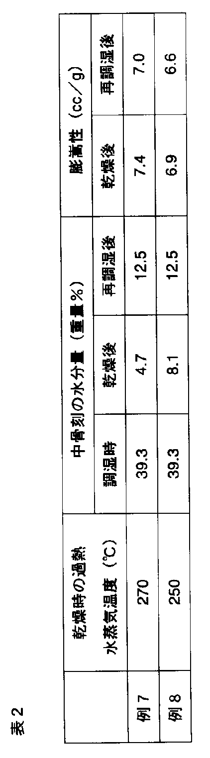
- the wet medium bone was dried and expanded in the same manner as in Example 7, except that the temperature of the superheated steam flow circulating with the wet medium bone was set to 250 ° C. Thereafter, water was sprayed on the incised bones to adjust the moisture content to 12.5% by weight.
- Example 7 and Example 8 (after drying) was stored (harmonized) in a constant temperature and humidity chamber at a temperature of 22.0 ° C. and a relative humidity of 60% for one week to obtain equilibrium moisture, and then described above.
- the bulkiness was measured in the same manner as in Examples 1 to 6.
- the bulkiness of the swollen medium after rehumidification was measured by the same method as in Examples 1 to 6.
- Examples 7 and 8 in which the sculptures during humidity control were wetted with a steam flow at a temperature of 125 ° C. before drying with a superheated steam flow, and were reconditioned after drying, respectively.
- the bulkiness is only reduced by about 4% compared to the midbone after drying (before reconditioning).
- Example 7 and Example 8 Compared to the swelling of the swelled medium of Example 7 and Example 8 as described above, the swelled of the swelled medium (after drying) of Example 3 as a comparative example described above, both are larger than the swelled form. I understand. Therefore, when the middle bone is expanded with the target of water content of 12% by weight, as compared with the case where the moisture content is made to be 11% by weight only by the drying process as in Example 3, the middle bone of the humidity is adjusted. It can be seen that Example 7 and Example 8 can significantly improve the bulkiness by applying moisture with a steam flow before drying with a superheated steam flow and adjusting the moisture content to 12% by weight after drying.
- the re-humidified bone engraving of Example 7 and Example 8 when comparing the bulkiness of the re-humidified bone engraving of Example 7 and Example 8 and the swollen middle bone of Example 1, the re-humidified bone engraving of Example 7 and Example 8 The bulkiness can be increased more than the swelled engraved bone of Example 1 (see Table 1), which is dried only to a moisture content of 5.4% by weight. Accordingly, even if rehumidification is performed to increase moisture after drying by applying moisture with a steam flow at a predetermined temperature before drying with a superheated steam flow as in the present invention, It was confirmed that the bulkiness can be significantly improved as compared with the conventional method in which only the drying process is performed.
Landscapes
- Manufacture Of Tobacco Products (AREA)
Abstract
Description
たばこ原料を100~160℃の水蒸気流と接触させてたばこ原料を湿潤、膨潤させる。
湿潤、膨潤させたたばこ原料を前記第1工程の水蒸気の温度より高い温度の過熱水蒸気流に接触させて前記たばこ原料を乾燥し、これによって膨化する。
この例1では、乾燥工程を図1の第2サイクロンおよび第2循環ダクトの系を用いて行った。
第2循環ダクト25において、調湿中骨刻と共に流通する過熱水蒸気流の温度をそれぞれ230℃、210℃にした以外、例1と同様な方法で調湿中骨刻を乾燥し、膨化した。
この例4では、前述した図1に示すたばこ原料の膨化装置を用いた。
第2循環ダクト25において、湿潤した中骨刻と共に流通する過熱水蒸気流の温度をそれぞれ240℃、220℃にした以外、例4と同様な方法で湿潤した中骨刻を乾燥し、膨化した。

この例7では、前述した図1に示すたばこ原料の膨化装置を用いた。
第2循環ダクト25において、湿潤した中骨刻と共に流通する過熱水蒸気流の温度を250℃にした以外、例7と同様な方法で湿潤した中骨刻を乾燥し、膨化した。その後、膨化中骨刻に水を噴霧して水分量を12.5重量%に再調湿した。
Claims (11)
- たばこ原料を100~160℃の水蒸気流と接触させてたばこ原料を湿潤、膨潤させる工程と、
前記湿潤、膨潤後の前記たばこ原料を前記水蒸気より高い温度の過熱水蒸気流に接触させて前記たばこ原料を乾燥する工程と
を含むたばこ原料の膨化方法。 - 前記水蒸気流との接触前のたばこ原料は、15~50重量%に調湿される請求項1記載のたばこ原料の膨化方法。
- 湿潤、膨潤した前記たばこ原料は、前記水蒸気流との接触前のたばこ原料と同じ水分量またはそれより5重量%以内に増加した水分量を有する請求項1記載のたばこ原料の膨化方法。
- 前記湿潤、膨潤工程は、前記たばこ原料を前記水蒸気流と共に旋回することによりなされる請求項1記載のたばこ原料の膨化方法。
- 前記旋回による滞留時間は、0.5~5秒間である請求項4記載のたばこ原料の膨化方法。
- 前記乾燥工程後に、前記たばこ原料を再調湿する請求項1記載のたばこ原料の膨化方法。
- 前記再調湿は、前記たばこ原料に水を噴霧することによりなされる請求項6記載のたばこ原料の膨化方法。
- 前記再調湿は、前記乾燥工程により10重量%以下の水分量に減少したたばこ原料に対して実行される請求項6記載のたばこ原料の膨化方法。
- 前記たばこ原料が中骨刻である請求項1ないし8いずれか1項記載のたばこ原料の膨化方法。
- 流入口、排気口および排出口を有する第1サイクロンと、
前記第1サイクロンの流入口に接続された第1供給側ダクトと、
前記第1サイクロンの排気口に接続される第1排気側ダクトと、
前記第1供給側ダクトに接続される第1水蒸気供給部と
前記第1水蒸気供給部の接続部と前記第1サイクロンの流入口の間に位置する前記第1供給側ダクトに接続される第1のたばこ原料供給部と、
流入口、排気口および排出口を有する第2サイクロンと、
前記第2サイクロンの流入口に接続された第2供給側ダクトと、
前記第2サイクロンの排気口に接続される第2排気側ダクトと、
前記第2供給側ダクトに配置される加熱部材と、
前記加熱部材より下流側に位置する前記第2供給側ダクトに接続される第2水蒸気供給部と、
前記第2サイクロンの流入口と前記加熱部材との間に位置する前記第2供給側ダクトに接続され第2のたばこ原料供給部と、
前記第1サイクロンの排出口から排出されたたばこ原料を前記第2のたばこ原料供給部に搬送するための搬送部材と
を備えるたばこ原料の膨化装置。 - 前記第1サイクロンに接続される前記第1供給側ダクトと前記第1排気側ダクトが繋がって第1循環ダクトを形成し、かつ前記第2サイクロンに接続される前記第2供給側ダクトと前記第2排気側ダクトが繋がって第2循環ダクトを形成し、前記第1サイクロンの排気口近傍に位置する前記第1循環ダクトと前記第2サイクロンの排気口近傍の前記第2循環ダクトとを連結ダクトで接続する請求項10記載のたばこ原料の膨化装置。
Priority Applications (7)
| Application Number | Priority Date | Filing Date | Title |
|---|---|---|---|
| PCT/JP2011/058340 WO2012132006A1 (ja) | 2011-03-31 | 2011-03-31 | たばこ原料の膨化方法およびその装置 |
| CN201180070584.4A CN103517646B (zh) | 2011-03-31 | 2011-03-31 | 烟草原料的膨化方法及其装置 |
| JP2013507008A JP5719924B2 (ja) | 2011-03-31 | 2011-03-31 | たばこ原料の膨化装置 |
| RU2013148553/12A RU2560306C2 (ru) | 2011-03-31 | 2011-03-31 | Способ расширения табачного материала и устройство для его осуществления |
| EP11862360.2A EP2692246B1 (en) | 2011-03-31 | 2011-03-31 | Method and apparatus for expanding tobacco material |
| US14/040,309 US20140026906A1 (en) | 2011-03-31 | 2013-09-27 | Method and apparatus for expanding tobacco material |
| US15/333,962 US20170035096A1 (en) | 2011-03-31 | 2016-10-25 | Method and apparatus for expanding tobacco material |
Applications Claiming Priority (1)
| Application Number | Priority Date | Filing Date | Title |
|---|---|---|---|
| PCT/JP2011/058340 WO2012132006A1 (ja) | 2011-03-31 | 2011-03-31 | たばこ原料の膨化方法およびその装置 |
Related Child Applications (1)
| Application Number | Title | Priority Date | Filing Date |
|---|---|---|---|
| US14/040,309 Continuation US20140026906A1 (en) | 2011-03-31 | 2013-09-27 | Method and apparatus for expanding tobacco material |
Publications (1)
| Publication Number | Publication Date |
|---|---|
| WO2012132006A1 true WO2012132006A1 (ja) | 2012-10-04 |
Family
ID=46929824
Family Applications (1)
| Application Number | Title | Priority Date | Filing Date |
|---|---|---|---|
| PCT/JP2011/058340 Ceased WO2012132006A1 (ja) | 2011-03-31 | 2011-03-31 | たばこ原料の膨化方法およびその装置 |
Country Status (6)
| Country | Link |
|---|---|
| US (2) | US20140026906A1 (ja) |
| EP (1) | EP2692246B1 (ja) |
| JP (1) | JP5719924B2 (ja) |
| CN (1) | CN103517646B (ja) |
| RU (1) | RU2560306C2 (ja) |
| WO (1) | WO2012132006A1 (ja) |
Families Citing this family (2)
| Publication number | Priority date | Publication date | Assignee | Title |
|---|---|---|---|---|
| GB201811370D0 (en) | 2018-07-11 | 2018-08-29 | British American Tobacco Investments Ltd | Methods of treating cut stem tobacco material |
| IT202000004129A1 (it) * | 2020-02-27 | 2021-08-27 | Magg Consulting S R L | Metodo perfezionato per il trattamento del tabacco. |
Citations (8)
| Publication number | Priority date | Publication date | Assignee | Title |
|---|---|---|---|---|
| US2802334A (en) | 1952-01-14 | 1957-08-13 | Rolls Royce | Gas turbine engines |
| JPS6070058A (ja) * | 1983-09-26 | 1985-04-20 | 日本たばこ産業株式会社 | たばこ中骨刻の膨化処理方法 |
| JPS623778A (ja) | 1985-06-15 | 1987-01-09 | ブリテイツシユ−アメリカン・タバコ・カンパニ−・リミテツド | たばこの乾燥処理方法及び装置 |
| US4766912A (en) | 1983-04-23 | 1988-08-30 | Korber Ag | Method and apparatus for puffing tobacco |
| JPH04144675A (ja) * | 1990-10-04 | 1992-05-19 | Japan Tobacco Inc | たばこ原料の膨化方法 |
| WO2003046453A1 (en) * | 2001-11-26 | 2003-06-05 | Japan Tobacco Inc. | Air flow dryer for granular material |
| JP2006520599A (ja) * | 2003-03-20 | 2006-09-14 | アール・ジェイ・レイノルズ タバコ カンパニー | 蒸気を用いたタバコの膨張方法 |
| JP4031115B2 (ja) | 1997-08-08 | 2008-01-09 | ハウニ・マシイネンバウ・アクチエンゲゼルシヤフト | たばこ材料にコンデイショニング剤を適用するための方法および装置 |
Family Cites Families (6)
| Publication number | Priority date | Publication date | Assignee | Title |
|---|---|---|---|---|
| US3683937A (en) * | 1970-12-24 | 1972-08-15 | Reynolds Leasing Corp | Tobacco expansion process |
| US4271852A (en) * | 1978-06-06 | 1981-06-09 | American Brands, Inc. | Method for increasing the filling capacity of tobacco |
| US4418706A (en) * | 1981-09-21 | 1983-12-06 | Office Of Monopoly | Method for expanding tobacco and apparatus therefor |
| DE4221573A1 (de) * | 1992-07-01 | 1994-01-05 | Hauni Werke Koerber & Co Kg | Verfahren und Anordnung zum Trocknen von Tabak |
| DE4320013A1 (de) * | 1993-06-17 | 1994-12-22 | Hauni Werke Koerber & Co Kg | Vorrichtung zum Behandeln von Tabak |
| DE10046124C1 (de) * | 2000-09-15 | 2002-07-04 | Reemtsma H F & Ph | Verfahren zur Verbesserung der Füllfähigkeit von Tabak |
-
2011
- 2011-03-31 EP EP11862360.2A patent/EP2692246B1/en active Active
- 2011-03-31 JP JP2013507008A patent/JP5719924B2/ja active Active
- 2011-03-31 WO PCT/JP2011/058340 patent/WO2012132006A1/ja not_active Ceased
- 2011-03-31 RU RU2013148553/12A patent/RU2560306C2/ru active
- 2011-03-31 CN CN201180070584.4A patent/CN103517646B/zh not_active Expired - Fee Related
-
2013
- 2013-09-27 US US14/040,309 patent/US20140026906A1/en not_active Abandoned
-
2016
- 2016-10-25 US US15/333,962 patent/US20170035096A1/en not_active Abandoned
Patent Citations (8)
| Publication number | Priority date | Publication date | Assignee | Title |
|---|---|---|---|---|
| US2802334A (en) | 1952-01-14 | 1957-08-13 | Rolls Royce | Gas turbine engines |
| US4766912A (en) | 1983-04-23 | 1988-08-30 | Korber Ag | Method and apparatus for puffing tobacco |
| JPS6070058A (ja) * | 1983-09-26 | 1985-04-20 | 日本たばこ産業株式会社 | たばこ中骨刻の膨化処理方法 |
| JPS623778A (ja) | 1985-06-15 | 1987-01-09 | ブリテイツシユ−アメリカン・タバコ・カンパニ−・リミテツド | たばこの乾燥処理方法及び装置 |
| JPH04144675A (ja) * | 1990-10-04 | 1992-05-19 | Japan Tobacco Inc | たばこ原料の膨化方法 |
| JP4031115B2 (ja) | 1997-08-08 | 2008-01-09 | ハウニ・マシイネンバウ・アクチエンゲゼルシヤフト | たばこ材料にコンデイショニング剤を適用するための方法および装置 |
| WO2003046453A1 (en) * | 2001-11-26 | 2003-06-05 | Japan Tobacco Inc. | Air flow dryer for granular material |
| JP2006520599A (ja) * | 2003-03-20 | 2006-09-14 | アール・ジェイ・レイノルズ タバコ カンパニー | 蒸気を用いたタバコの膨張方法 |
Also Published As
| Publication number | Publication date |
|---|---|
| EP2692246A1 (en) | 2014-02-05 |
| RU2560306C2 (ru) | 2015-08-20 |
| US20140026906A1 (en) | 2014-01-30 |
| CN103517646A (zh) | 2014-01-15 |
| JPWO2012132006A1 (ja) | 2014-07-24 |
| EP2692246B1 (en) | 2018-05-09 |
| CN103517646B (zh) | 2016-05-25 |
| RU2013148553A (ru) | 2015-05-20 |
| EP2692246A4 (en) | 2015-06-17 |
| JP5719924B2 (ja) | 2015-05-20 |
| US20170035096A1 (en) | 2017-02-09 |
Similar Documents
| Publication | Publication Date | Title |
|---|---|---|
| JP5948316B2 (ja) | たばこ原料の膨化方法およびその装置 | |
| JP3964789B2 (ja) | タバコの処理方法 | |
| CA1105344A (en) | Tabacco drying process | |
| US7556047B2 (en) | Method of expanding tobacco using steam | |
| US3734104A (en) | Method for expanding tobacco stems | |
| EP2008534B1 (en) | Apparatus for producing a flavor for expanded tobacco material and method of producing the same | |
| JPH04173079A (ja) | たばこ原料の気流乾燥方法およびその装置 | |
| JP7185008B2 (ja) | 刻み葉柄タバコ材の処理方法 | |
| US4483352A (en) | Method of increasing the volume of cut tobacco ribs and an apparatus for carrying out said method | |
| JP5719924B2 (ja) | たばこ原料の膨化装置 | |
| NL7907904A (nl) | Werkwijze voor het behandelen van geeexpandeerde tabak. | |
| GB1601920A (en) | Method of treating tobacco material | |
| GB2426566A (en) | Tobacco dryer comprising a closed processing chamber formed by starwheel airlocks | |
| GB2187077A (en) | Tobacco treating process | |
| WO2009127641A1 (en) | Process for preparing a tobacco blend | |
| EP0325630B1 (en) | Apparatus for expanding and/or drying particulate material | |
| JP5531157B2 (ja) | 中骨刻の製造方法、中骨刻の製造装置および中骨刻 | |
| US4687007A (en) | Process for drying and expanding tobacco | |
| RU2613578C2 (ru) | Способ вспучивания табачного сырьевого материала и система его вспучивания | |
| KR20150095750A (ko) | 녹말 함유 제품을 팽창시키는 방법 및 장치 | |
| KR900002029B1 (ko) | 기류 건조에 의한 가향 판상엽의 제조방법 | |
| JPS6054030B2 (ja) | たばこ中骨の解繊刻み膨化方法 |
Legal Events
| Date | Code | Title | Description |
|---|---|---|---|
| 121 | Ep: the epo has been informed by wipo that ep was designated in this application |
Ref document number: 11862360 Country of ref document: EP Kind code of ref document: A1 |
|
| ENP | Entry into the national phase |
Ref document number: 2013507008 Country of ref document: JP Kind code of ref document: A |
|
| NENP | Non-entry into the national phase |
Ref country code: DE |
|
| WWE | Wipo information: entry into national phase |
Ref document number: 2011862360 Country of ref document: EP |
|
| ENP | Entry into the national phase |
Ref document number: 2013148553 Country of ref document: RU Kind code of ref document: A |