WO2012132016A1 - Système de communications, dispositif de station de base, dispositif terminal, et procédé de communications - Google Patents
Système de communications, dispositif de station de base, dispositif terminal, et procédé de communications Download PDFInfo
- Publication number
- WO2012132016A1 WO2012132016A1 PCT/JP2011/058355 JP2011058355W WO2012132016A1 WO 2012132016 A1 WO2012132016 A1 WO 2012132016A1 JP 2011058355 W JP2011058355 W JP 2011058355W WO 2012132016 A1 WO2012132016 A1 WO 2012132016A1
- Authority
- WO
- WIPO (PCT)
- Prior art keywords
- base station
- communication
- terminal
- comp
- unit
- Prior art date
- Legal status (The legal status is an assumption and is not a legal conclusion. Google has not performed a legal analysis and makes no representation as to the accuracy of the status listed.)
- Ceased
Links
Images













Classifications
-
- H—ELECTRICITY
- H04—ELECTRIC COMMUNICATION TECHNIQUE
- H04B—TRANSMISSION
- H04B7/00—Radio transmission systems, i.e. using radiation field
- H04B7/02—Diversity systems; Multi-antenna system, i.e. transmission or reception using multiple antennas
- H04B7/022—Site diversity; Macro-diversity
- H04B7/024—Co-operative use of antennas of several sites, e.g. in co-ordinated multipoint or co-operative multiple-input multiple-output [MIMO] systems
-
- H—ELECTRICITY
- H04—ELECTRIC COMMUNICATION TECHNIQUE
- H04J—MULTIPLEX COMMUNICATION
- H04J11/00—Orthogonal multiplex systems, e.g. using WALSH codes
- H04J11/0023—Interference mitigation or co-ordination
- H04J11/005—Interference mitigation or co-ordination of intercell interference
- H04J11/0053—Interference mitigation or co-ordination of intercell interference using co-ordinated multipoint transmission/reception
-
- H—ELECTRICITY
- H04—ELECTRIC COMMUNICATION TECHNIQUE
- H04J—MULTIPLEX COMMUNICATION
- H04J13/00—Code division multiplex systems
- H04J13/10—Code generation
- H04J13/12—Generation of orthogonal codes
-
- H—ELECTRICITY
- H04—ELECTRIC COMMUNICATION TECHNIQUE
- H04L—TRANSMISSION OF DIGITAL INFORMATION, e.g. TELEGRAPHIC COMMUNICATION
- H04L5/00—Arrangements affording multiple use of the transmission path
- H04L5/003—Arrangements for allocating sub-channels of the transmission path
- H04L5/0032—Distributed allocation, i.e. involving a plurality of allocating devices, each making partial allocation
- H04L5/0035—Resource allocation in a cooperative multipoint environment
-
- H—ELECTRICITY
- H04—ELECTRIC COMMUNICATION TECHNIQUE
- H04L—TRANSMISSION OF DIGITAL INFORMATION, e.g. TELEGRAPHIC COMMUNICATION
- H04L5/00—Arrangements affording multiple use of the transmission path
- H04L5/0091—Signalling for the administration of the divided path, e.g. signalling of configuration information
- H04L5/0096—Indication of changes in allocation
-
- H—ELECTRICITY
- H04—ELECTRIC COMMUNICATION TECHNIQUE
- H04W—WIRELESS COMMUNICATION NETWORKS
- H04W72/00—Local resource management
- H04W72/50—Allocation or scheduling criteria for wireless resources
- H04W72/54—Allocation or scheduling criteria for wireless resources based on quality criteria
- H04W72/541—Allocation or scheduling criteria for wireless resources based on quality criteria using the level of interference
-
- H—ELECTRICITY
- H04—ELECTRIC COMMUNICATION TECHNIQUE
- H04L—TRANSMISSION OF DIGITAL INFORMATION, e.g. TELEGRAPHIC COMMUNICATION
- H04L5/00—Arrangements affording multiple use of the transmission path
- H04L5/0001—Arrangements for dividing the transmission path
- H04L5/0014—Three-dimensional division
- H04L5/0023—Time-frequency-space
Definitions
- the present invention relates to a communication system, a base station device, a terminal device, and a communication method.
- W-CDMA Wideband-Code Division Multiple Access
- LTE Long Term Evolution
- LTE-Advanced system LTE-Advanced system
- the W-CDMA system has already been serviced as HSDPA (W-CDMA Release (hereinafter abbreviated as “Rel '”) 5) or HSPA (HSDPA + HSUPA W-CDMA Rel'6), and is an improved version of Rel'.
- HSDPA W-CDMA Release
- HSPA HSUPA + HSUPA W-CDMA Rel'6
- LTE has been formulated as LTE Rel'8.
- LTE Rel'9 specification with MBMS (Multimedia Broadcast Multicast Service) function added has been formulated, and the LTE-Advanced system specification, which is an advanced form of the LTE system, is now being considered as LTE Rel'10.
- the specification is being developed.
- LTE Rel'11 has also started.
- One of the technologies that are being studied for introduction in this LTE Rel'11 is the introduction of CoMP (Coordinate Multi Point transmission and reception) (for example, see Non-Patent Documents 1 and 2).
- CoMP includes Network MIMO (Multiple Input Multiple Output), SDM (Spatial Division Multiplex: Spatial Multiplexing), ICIC (Inter Cell Interference Coordination), etc. It is aimed. Therefore, the embodiments differ depending on the above purpose. For example, in downlink transmission, JP (Joint Processing) and CS / CB (Coordinated Scheduling / Coordinated Beamforming) are being studied. Also, in uplink transmission, JR (Joint Reception), CS (Coordinated Scheduling) and the like are being studied.
- the LTE-Advanced system is an extension of the LTE system and is required to be compatible with the LTE system. That is, there are places where the LTE specification is continued without being changed. In particular, if the baseband signal processing (so-called channel coding) is changed, the device is recreated, so that compatibility with the LTE system is required. That is, the baseband signal processing must be basically the same as the LTE specification or based on the LTE specification.
- PDSCH Physical Downlink Shared Channel
- PMCH Physical Multicast Channel
- signal processing in downlink transmission is performed corresponding to the LTE specification. Specifically, first, transmission data (bit) is scrambled. Further, the scrambled data (bit) is mapped in accordance with the modulation method to create a symbol. For example, in the case of QPSK, 2 bits are mapped to the I channel and the Q channel to create one symbol. There is a communication technique using scrambling described above (see, for example, Patent Documents 1 and 2).
- multiple series of data (for example, symbols mapped to IQ) are each mapped to a layer (equivalent to a MIMO stream). Further, in the case of MIMO, a plurality of PDSCH symbols are multiplied by Precoding Matrix. Symbols are mapped to the radio channel PhyCH (eg PDSCH) or PMCH). Finally, it is converted into an OFDM signal.
- PhyCH radio channel
- TR36.912V9.3.0 Feasibility study for Further Advances for E-UTRAN (LTE-Advanced) (Release 9)
- TR36.814V9.0.0 Further Advancements for E-UTRAN Physical Layer Aspects (Release 9)”
- TS36.211V9.1.0 Physical Channel and Modulation (Release 9)"
- the initial value of the scrambling code described above is different.
- the cell number (set for each cell), physical cell ID, and slot number (the setting range is the same but not necessarily the same between cells) of the terminal differ from cell to cell.
- the initial value of the scrambling code differs between cells, and as a result, the scrambling code between cells differs. That is, in the signal processing for CoMP transmission, different scrambling is performed between cells.
- downlink CoMP is used.
- uplink CoMP transmission that is, when transmitting from one terminal to a plurality of cells, the cell ID, terminal number, and slot number of each cell are used). It becomes necessary to create a plurality of scrambling codes and perform scrambling.
- the disclosed technology has been made in view of the above-described problems, and provides a communication system, a base station device, a terminal device, and a communication method that can reduce processing in a terminal device or a base station device. For the purpose.
- a communication system is a communication system that performs wireless communication using a terminal device and first and second base station devices having one or a plurality of cells, the first base station device When performing cooperative communication with the terminal device in cooperation with the second base station device which is another base station, communication conditions used for transmission / reception signal processing in wireless communication with the terminal device, etc.
- wireless communications system in 1st Embodiment The figure which shows the block structural example of the master base station in 1st Embodiment.
- Sequence showing communication processing example (modification 3) in the first embodiment The sequence which shows the communication processing example (modification 4) in 1st Embodiment.
- Sequence showing communication processing example (modification 5) in the first embodiment The figure which shows the structural example of the radio
- the sequence which shows the example of a communication process in 7th Embodiment The sequence which shows the communication processing example (modification 1) in 7th Embodiment.
- the sequence which shows the example of a communication process in 8th Embodiment The sequence which shows the communication processing example (modification 1) in 8th Embodiment.
- Radio communication system 100 Base station apparatus 101, 201 Antenna part 102, 202 Reception radio part 103, 203 Demodulation / decoding part 104 Radio channel quality information extraction part 105 Scheduler 106 CoMP communication request signal extraction part 107 CoMP communication execution judgment and control part 108 Connection Request Signal Extraction Unit 109 Radio Channel Control Unit 110 RNTI Setting Unit 111 CoMP-RNTI Setting Unit 112, 208 Scrambling Code Creation Unit 113 System Information Creation Unit 114 Transmission Data Buffer 115 Control Signal Creation Unit 116, 214 Encoding / Modulation Units 117 and 215 Transmission radio unit 118 Radio channel quality measurement calculation unit 119 CoMP communication control unit 120 Offset setting / storage unit 200 Terminal device 204 Calculation unit 205 Radio channel quality information creation unit 206 Cell information extraction 207 CoMP-RNTI extraction unit 209 reception control signal extraction unit 210 terminal setting control unit 211 reception power measurement unit 212 line connection control unit 213 connection request signal creation unit 216 slot number extraction unit 217 system information extraction unit
- FIG. 1 is a diagram illustrating a configuration example of a wireless communication system according to the first embodiment.
- 1 includes two base station apparatuses (eNB: evolved Node B, hereinafter referred to as “base station”) 100-1 and 100-2 and terminal apparatuses (UE: User Equipment, hereinafter referred to as “terminal”). 200).
- Base stations 100-1 and 100-2 transmit different data, and terminal 200 receives this (downlink direction).
- Terminal 200 can also transmit different data to base stations 100-1 and 100-2 (uplink direction). Both the base stations 100-1 and 100-2 and the terminal 200 can perform so-called CoMP communication.
- the base station 100-1 is a master base station (main base station, serving base station, first base station, Serving cell), and the base station 100-2 is a slave base station. Station (subordinate base station, non-serving base station, second base station, non-serving cell).
- the master base station 100-1 is, for example, a base station that is connected to the terminal 200 before performing CoMP transmission
- the slave base station 100-2 is, for example, a base station that performs CoMP transmission.
- Master base station 100-1 transmits a control signal to terminal 200.
- the terminal 200 receives different transmission data (DSCH) transmitted from the master base station 100-1 and the slave base station 100-2 based on the control signal.
- DSCH transmission data
- a certain terminal connects to a certain cell (for example, cell 1), and from a base station (for example, master base station (eNB1)) that configures the connected cell 1, for example, It is assumed that the terminal is using RNTI when notified of using C-RNTI (or RNTI (Radio Network Temporary Identifier), hereinafter referred to as “RNTI”).
- C-RNTI Radio Network Temporary Identifier
- the first embodiment it is determined that communication is possible for the cell 2 based on, for example, another cell (for example, the cell 2) and the radio channel quality (for example, reception quality or reception electric field strength). .
- the radio channel quality for example, reception quality or reception electric field strength.
- the base station of the cell 1 that is connected from the beginning, apart from the RNTI that has already been notified, CoMP-RNTI (CoMP transmission terminal identification information), which is a new RNTI for CoMP transmission, is notified to the terminal. That is, in the first embodiment, terminal identification information that is used only when data is switched from a plurality of base stations to a terminal at the same time or by switching time is set.
- the terminal that has received the notification uses CoMP-RNTI for CoMP transmission.
- the RNTI that has been used so far may be kept unused or may be discarded.
- the CoMP transmission becomes impossible, and it is used again when the normal data transmission is started.
- the RNTI newly notified from the previous base station (eNB1) or another base station (for example, eNBn) is used.
- cell ID Cell ID
- slot number for example, slot number
- CoMP-RNTI cell ID
- eNB 2 slave base station
- the base station selects the CoMP-RNTI described above from a plurality of preset CoMP-RNTIs.
- a plurality of CoMP-RNTIs set in advance may be the same or different among, for example, a wireless communication system, a wireless network, an operator providing a wireless communication service, and a base station.
- the master base station the CoMP-RNTI (n CoMP-RNTI ), a cell ID (N ID cell) and, because the slot number (n s), the initial value c scrambling code using the following equation (1) init is calculated.
- q is a constant.
- a scrambling code is created from the following equation (2) using the initial value calculated using the above equation (1).
- the transmission data b (0),..., B (M bit ⁇ 1) and the generated scrambling code are used for scrambling.
- the slave base station of cell 2 notified of CoMP-RNTI and the like scrambles and transmits data for the terminal based on such information.
- different data may be transmitted simultaneously from the master base station and the slave base station, or different or the same data may be transmitted from either one by switching over time (described later). The same applies to the other examples).
- the terminal that receives these calculates the initial value of the scrambling code based on the system information such as CoMP-RNTI notified from the master base station, and creates the scrambling code.
- the transmission data is reproduced by solving the descrambling (descrambling) based on the above-described equation (3).
- the case of downlink transmission is shown as an example.
- the present invention is not limited to this.
- it can be similarly applied to scrambling of uplink data in a terminal.
- CoMP transmission control is performed using the connected base station eNB1 as a master base station before CoMP transmission.
- the base station eNB2 that performs CoMP transmission is a slave base station.
- the terminal requests CoMP transmission to the master base station and slave base station, or the master base station requests CoMP transmission to the terminal and slave base station. Further, in order to determine whether CoMP transmission is possible according to the CoMP request, the result of the terminal measuring the radio channel quality with the slave base station (for example, radio channel quality index CQI2) is sent to the master base station via the slave base station. Notify or notify the master base station directly from the terminal.
- radio channel quality index CQI2 radio channel quality index
- the master base station that has received the notification determines whether or not CoMP transmission is possible using the radio channel quality indicator CQI1 between the terminal and the master base station and the CQI2 described above.
- the master base station when it is determined that CoMP transmission is possible, the master base station notifies the slave base station and the terminal that CoMP transmission is performed, and the CoMP-RNTI, (physical) cell ID (N ID cell ), and slot number are notified. Notify ( ns ). Thereafter, the signal processing described above is performed.
- one radio resource for example, one frequency
- one service area of one base station For example, in the case of a base station that configures 6 sectors with 4 frequencies, it looks like one base station, but in reality it can be interpreted as 24 base stations.
- CoMP in addition to the case where CoMP is performed in two base stations having different appearances, CoMP can be performed between sectors if the sectors are different even if the base station is apparent. Even in such a case, the above-described method can be used.
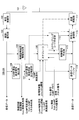
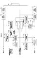
- FIG. 2 is a diagram illustrating a block configuration example of the master base station in the first embodiment.
- the master base station 100-1 shown in FIG. 2 includes an antenna unit 101, a reception radio unit 102, a demodulation / decoding unit 103, a radio channel quality information extraction unit 104, a scheduler 105, and a CoMP communication request signal extraction unit 106.
- control unit 107 A CoMP communication execution determination and control unit (hereinafter referred to as “control unit”) 107, a connection request signal extraction unit 108, a radio channel control unit 109, an RNTI setting unit 110, a CoMP-RNTI setting unit 111, A scrambling code creation unit 112, a system information creation unit 113, a transmission data buffer 114, a control signal creation unit 115, an encoding / modulation unit 116, and a transmission radio unit 117 are included.
- control unit 107 A CoMP communication execution determination and control unit (hereinafter referred to as “control unit”) 107, a connection request signal extraction unit 108, a radio channel control unit 109, an RNTI setting unit 110, a CoMP-RNTI setting unit 111, A scrambling code creation unit 112, a system information creation unit 113, a transmission data buffer 114, a control signal creation unit 115, an encoding / modulation unit 116, and a transmission radio unit 117 are included.
- the reception unit includes the reception radio unit 102 and the demodulation / decoding unit 103
- the transmission unit includes the encoding / modulation unit 116 and the transmission radio unit 117.
- the demodulation / decoding unit 103 includes a descrambling unit
- the encoding / modulation unit 116 includes a scramble unit.
- the antenna unit 101 transmits and receives radio signals to and from the terminal 200.
- the reception radio unit 102 outputs the radio signal received by the antenna unit 101 as a reception signal.
- the demodulation / decoding unit 103 demodulates and decodes the reception signal output from the reception radio unit 102.
- Radio channel quality information extraction section 104 extracts radio channel quality information from the received signal output from demodulation / decoding section 103.
- the wireless channel quality information is information transmitted from the terminal 200, for example.
- Radio channel quality information extraction section 104 outputs the extracted radio channel quality information to scheduler 105 and control section 107.
- scheduler 105 determines the coding rate, modulation method, etc. used for downlink communication with terminal 200 (performs scheduling). .
- the scheduler 105 outputs scheduling information related to the determined coding rate and the like to the control signal creation unit 115. Also, the scheduler 105 transmits used radio resources and precoding information (precoding information) of the scheduling information as a CoMP control signal to the slave base station 100-2, and sets the transmission slot number to the system information creation unit 113 and the scrambling code.
- the data is output to the creation unit 112.
- the radio resource is a grid composed of a time domain and a frequency domain (that is, a subcarrier) in the LTE system, and a minimum unit is called an RB (Resource Block).
- the scheduler 105 controls the encoding / modulation unit 116 and the transmission radio unit 117 so that the transmission data is encoded based on the determined scheduling information.
- the CoMP communication request signal extraction unit 106 extracts a CoMP communication request signal from the reception signals output from the demodulation / decoding unit 103.
- the CoMP communication request signal is a signal transmitted from the terminal 200 when the terminal 200 wants to perform CoMP communication, for example.
- the control unit 107 determines whether or not to perform CoMP transmission, and when determining that CoMP transmission is to be performed, notifies the slave base station 100-2 of a CoMP transmission execution notification.
- the control unit 107 for example, based on the radio channel quality output from the radio channel quality information extraction unit 104 and the radio channel quality transmitted from the adjacent base station (for example, the slave base station 100-2). Then, it is determined whether or not to perform CoMP transmission.
- the CoMP transmission execution notification is output to the scheduler 105, the wireless channel control unit 109, and the system information creation unit 113. Details of CoMP transmission execution determination will be described later.
- connection request signal extraction unit 108 extracts a connection request signal from the demodulated received signal.
- the connection request signal is a signal used when, for example, the terminal 200 requests a line connection with the master base station 100-1.
- the wireless channel control unit 109 inputs a connection request signal from the connection request signal extraction unit 108. Further, when the CoMP transmission execution notification is input from the control unit 107, the radio line control unit 109, for example, one of a plurality of cell numbers held therein and the CoMP-RNTI setting unit 111 sets CoMP-RNTI is output to the scrambling code creation unit 112 and the system information creation unit 113. Further, when the CoMP transmission execution notification is not input from the control unit 107 (that is, when CoMP transmission is not performed), the wireless line control unit 109, for example, any one of a plurality of cell numbers held inside The RNTI set by the RNTI setting unit 110 is output to the scrambling code creation unit 112 and the system information creation unit 113.
- the RNTI setting unit 110 sets the RNTI corresponding to the RNTI setting request from the radio line control unit 109, and outputs the set RNTI to the radio line control unit 109.
- the CoMP-RNTI setting unit 111 sets CoMP-RNTI corresponding to the CoMP-RNTI setting request from the radio channel control unit 109, and outputs the set CoMP-RNTI to the radio channel control unit 109.
- the scrambling code creation unit 112 creates an initial value of the scrambling code based on, for example, the transmission slot number output from the scheduler 105, the cell number output from the radio channel control unit 109, and the CoMP-RNTI. Then, scrambling codes are created sequentially. The details of the scrambling code creation unit 112 will be described later. In addition, scrambling code creation section 112 outputs the created scrambling code to encoding / modulation section 116.
- the system information creation unit 113 creates cell information from the cell number and CoMP-RNTI output from the radio channel control unit 109 and the transmission slot number output from the scheduler 105.
- the created cell information is transmitted as a cell information signal to a base station (for example, slave base station 100-2) that performs CoMP transmission.
- the cell information signal is also output to encoding / modulation section 116 for transmission to terminal 200.
- the transmission data buffer 114 temporarily stores transmission data transmitted from the master base station 100-1 to the terminal 200.
- the control signal creation unit 115 creates a control signal including scheduling information output from the scheduler 105 and outputs the control signal to the encoding / modulation unit 116.
- the encoding / modulation unit 116 encodes the transmission data output from the transmission data buffer 114 based on the scheduling information obtained from the scheduler 105, and uses the scrambling code generated by the scrambling code generation unit 112, The encoded transmission data is scrambled (scrambled). Also, the encoding / modulation unit 116 modulates the scrambled transmission data based on the scheduling information obtained from the scheduler 105. The encoding / modulating unit 116 performs processing such as encoding on the cell information output from the system information generating unit 113 and the control signal output from the control signal generating unit 115. May be scrambled.
- transmission radio section 117 transmission data and the like output from the encoding / modulation section 116 are subjected to weighting processing and the like on the transmission data and the like by the scheduler 105 according to the created precoding information (Precoding information). .
- the transmission radio unit 117 generates a pilot signal (or a known signal), for example. An output from the transmission radio unit 117 is transmitted to the terminal 200 via the antenna unit 101 as a radio signal.
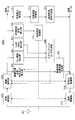
- FIG. 3 is a diagram illustrating a block configuration example of the slave base station according to the first embodiment.
- blocks having substantially the same functions as those of the master base station 100-1 described above are denoted by the same reference numerals, and detailed description thereof is omitted here. To do.
- the slave base station 100-2A shown in FIG. 3 includes an antenna unit 101, a reception radio unit 102, a demodulation / decoding unit 103, a radio channel quality information extraction unit 104, a scheduler 105, and a CoMP communication request signal extraction unit 106.
- control unit 107 When the control unit 107 receives the CoMP communication request signal from the CoMP communication request signal extraction unit 106 and further receives the CoMP execution notification from the master base station 100-1, the control unit 107 outputs the CoMP execution notification to the scheduler 105.
- the scheduler 105 performs downlink scheduling based on the radio channel quality information output from the radio channel quality information extraction unit 104. Further, when the scheduler 105 receives the CoMP execution notification from the control unit 107 and receives the CoMP control signal from the master base station 100-1, the scheduler 105 performs scheduling for CoMP transmission. Further, the scheduler 105 controls the encoding / modulation unit 116 and the transmission radio unit 117 so that encoding processing and the like are performed according to the scheduling.
- the scrambling code creation unit 112 receives cell information (cell number, CoMP-RNTI, transmission slot number) from the master base station 100-1, creates an initial value of the scrambling code based on the cell information, and sequentially scrambles Create a ring code. Details thereof will be described later. Since the scrambling code creation unit 112 creates a scrambling code based on the cell information notified from the master base station 100-1, the master base station 100-1 and the slave base station 100-2 have the same scrambling code. Create The generated scrambling code is output to the encoding / modulation unit 116, and the transmission data transmitted from the slave base station 100-2 is scrambled.
- cell information cell number, CoMP-RNTI, transmission slot number
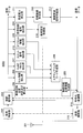
- FIG. 4 is a diagram illustrating a configuration example of a terminal according to the first embodiment. 4 includes an antenna unit 201, a reception radio unit 202, a demodulation / decoding unit 203, a radio channel quality measurement and calculation unit (hereinafter referred to as “calculation unit”) 204, and radio channel quality information generation.
- Unit 205 Cell information extraction unit 206, CoMP-RNTI extraction unit 207, scrambling code creation unit 208, reception control signal extraction unit 209, terminal setting control unit 210, received power measurement unit 211, line A connection control unit 212, a connection request signal creation unit 213, an encoding / modulation unit 214, and a transmission radio unit 215 are included.
- the antenna unit 201 transmits and receives radio signals to and from the base stations 100-1 and 100-2.
- Reception radio section 202 outputs the radio signal received by antenna section 201 as a received signal.
- the demodulating unit / decoding unit 203 demodulates the received signal according to the demodulation method set by the terminal setting control unit 210, and is demodulated using the scrambling code created by the scrambling code creation unit 208.
- the signal is descrambled (descrambled), and the descrambled received signal is decoded according to the coding rate set by the terminal setting control unit 210.
- the calculation unit 204 measures the radio quality of each radio channel with respect to a pilot signal or the like transmitted from the master base station 100-1 or the slave base station 100-2. Note that the calculation unit 204 measures the radio channel quality by measuring, for example, SINR (Signal to Interference Noise Ratio) of the pilot signal.
- SINR Signal to Interference Noise Ratio
- the radio channel quality information creation unit 205 creates radio channel quality information based on the radio channel quality output from the calculation unit 204.
- the wireless channel quality information is, for example, CQI (Channel I Quality Indicator).
- the created wireless channel quality information is output to encoding / modulation section 214.
- the cell number extraction unit 206 extracts a cell number from the received signal output from the demodulation / decoding unit 203.
- the cell number extraction unit 206 outputs the extracted cell number to the scrambling code creation unit 208.
- the CoMP-RTNI extraction unit 207 extracts the CoMP-RTNI from the received signal output from the demodulation / decoding unit 203.
- the CoMP-RTNI extraction unit 207 outputs the extracted CoMP-RTNI to the scrambling code generation unit 208.
- the scrambling code creation unit 208 creates an initial value of the scramble code based on the cell information (for example, including the cell number and CoMP-RNTI), and sequentially creates the scrambling code.
- the scrambling code creation unit 208 outputs the created scramble code to the demodulation / decoding unit 203.
- the reception control signal extraction unit 209 extracts a control signal from the reception signals and outputs it to the terminal setting control unit 210.
- Terminal setting control section 210 receives radio section 202 and demodulation / decoding section so as to demodulate and decode received data from base stations 100-1 and 100-2 based on scheduling information included in the control signal. 203 is controlled.
- the received power measuring unit 211 measures, for example, the received power of a pilot signal among the received signals, and outputs the measurement result to the line connection control unit 212. Further, line connection control section 212 determines whether or not to connect a line with base stations 100-1 and 100-2 based on the received power obtained from received power measuring section 211.
- connection request signal creation unit 213 creates a connection request signal based on the instruction signal and outputs the connection request signal to the encoding / modulation unit 214.
- the encoding / modulation unit 214 performs encoding and modulation processing on radio channel quality information, connection request signals, and the like.
- the transmission radio unit 214 performs control of transmission power on the encoded radio channel quality information and the like, and outputs the radio signal to the antenna unit 201. Thereby, the radio channel quality information and the like are transmitted from the antenna unit 201 to the base stations 100-1 and 100-2 as radio signals.
- FIG. 5 is a diagram illustrating a configuration example (modification example 1) of the terminal according to the first embodiment.
- blocks having substantially the same functions as those of the terminal 200 ⁇ / b> A illustrated in FIG. 4 described above are denoted by the same reference numerals, and detailed description thereof is omitted here.
- Terminal 200B shown in FIG. 5 includes antenna section 201, reception radio section 202, demodulation / decoding section 203, calculation section 204, radio channel quality information creation section 205, cell information extraction section 206, CoMP-RNTI. Extraction unit 207, scrambling code creation unit 208, reception control signal extraction unit 209, terminal setting control unit 210, reception power measurement unit 211, line connection control unit 212, connection request signal creation unit 213, code A modulation / modulation unit 214, a transmission radio unit 215, and a slot number extraction unit 216.
- the terminal 200B in the first modification is provided with a slot number extraction unit 216 as compared with the terminal 200A in the first embodiment described above.
- the slot number extraction unit 216 extracts the slot number from the received signal output from the demodulation / decoding unit 203.
- the slot number extraction unit 207 outputs the extracted slot number to the scrambling code generation unit 208.
- the scrambling code creation unit 208 creates an initial value of the scramble code based on the cell information (including the cell number, CoMP-RNTI, and slot number in the first modification), and sequentially adds the scrambling code. create.
- the scrambling code creation unit 208 outputs the created scramble code to the demodulation / decoding unit 203.
- Demodulation / decoding section 203 descrambles the received data using the scrambling code obtained from scrambling code creation section 208.
- FIG. 6 is a diagram illustrating a configuration example of the scrambling code creation unit.
- the scrambling code generators 112 and 208 include first and second registers (or flip-flops) 112-1 and 112-2, first to third exclusive OR circuits 112-3 to 112-5, Have
- the scrambling code creation units 112 and 208 generate, for example, a gold code (or scrambling code) having a length of “31”, and an output thereof is a scrambling code c (n).
- the generator polynomial of the scramble code c (n) is expressed by the above-described equation (2).
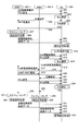
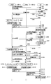
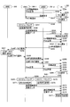
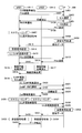
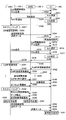
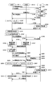
- FIG. 7 is a sequence showing an example of communication processing in the first embodiment.
- UE terminal
- eNB1 master base station
- eNB2 slave base station
- the master base station 100-1 broadcasts the information of the cell (Cell) to the terminal 200 (S01).
- Master base station 101-1 transmits a common pilot (Pilot) to terminal 200 (S02).
- the pilot signal is generated by the transmission radio unit 117 of the master base station 100-1.
- the terminal 200 that has received the common pilot selects a cell to be communicated (S03), and sets a line with the selected cell (S04).
- the reception power measuring unit 211 of the terminal 200 measures the reception power of the pilot signal
- the line connection control unit 212 has a cell with the best reception quality (for example, the largest reception power) (for example, the master base station 100-1 ) Is selected.
- the connection request signal creation unit 213 creates a connection request signal and transmits it to the master base station 100-1 to set a line.
- the terminal 200 sets a wireless line with the master base station 100-1.
- the network including master base station 100-1 sets terminal identification number RNTI for terminal 200 and notifies terminal 200.
- the terminal 200 After completing the wireless channel setting, the terminal 200 measures the quality of the wireless channel (for example, CQI (Channel Quality Indicator)) based on the common pilot (S05). In addition, terminal 200 notifies measured radio channel quality information to master base station 100-1. In this case, for example, the calculation unit 204 of the terminal 200 measures the radio channel quality based on the pilot signal, the radio channel quality information creation unit 205 creates the radio channel quality information, and the information is the master base station 100-1 Sent to.
- CQI Channel Quality Indicator
- the master base station 100-1 performs scheduling based on the radio channel quality information (S06).
- the scheduler 105 of the master base station 100-1 performs scheduling based on the radio channel quality information extracted by the radio channel quality information extraction unit 104.
- the master base station 100-1 performs transmission signal processing.
- the master base station 100-1 that has received the notification of the radio channel quality information (for example, CQI) from the terminal 200 is connected to any terminal on the basis of each CQI notified from other terminals.
- the user selects whether to perform downlink communication (selects a communication partner terminal).
- the master base station 100 selects, for example, a transmission method (modulation scheme and coding rate) and a radio resource to be used, and notifies the terminal 200 of it. In the following description, the case of downlink will be described.
- master base station 100-1 performs signal processing such as encoding / modulation by encoding / modulating section 116 on the transmission control signal created based on the selected transmission method, and performs transmission control after processing.
- a signal is transmitted to the terminal 200 (S09).
- the master base station 100-1 performs signal processing such as encoding / modulation on the transmission data by the encoding / modulation unit 116, and transmits the processed transmission data to the terminal 200 (S10).
- the terminal 200 performs received signal processing (S11). Specifically, the terminal 200 receives the control signal, demodulates and decodes it by the demodulation / decoding unit 203, and acquires the control signal. Also, the terminal 200 receives the transmission data, and demodulates and decodes the data based on the acquired transmission control signal by the demodulation / decoding unit 203 to acquire the data.
- S11 received signal processing
- the terminal 200 performs CoMP transmission determination (S12). Specifically, the terminal 200 receives cell information or a pilot transmitted from another base station (for example, the slave base station 100-2) intermittently or periodically even during the above-described communication. Receive (S13, S14), and measure and calculate the radio quality with other base stations.
- the radio channel quality with the master base station 100-1 deteriorates and the transmission characteristics deteriorate due to the terminal 200 moving to the cell edge.
- the terminal 200 determines that transmission characteristics can be improved by performing CoMP transmission from the master base station 100-1 and other base stations, the radio channel quality of the master base station 100-1 Whether or not CoMP transmission is possible is determined from (for example, CQI) and the radio channel quality of other base stations, and a cell (for example, slave base station 100-2) that performs CoMP transmission is selected (S15).
- the terminal 200 requests the master base station 100-1 to perform CoMP transmission with the slave base station 100-2 (S16).
- the master base station 100-1 that has received the CoMP transmission request notifies the slave base station 100-2 and the terminal 200 of CoMP transmission execution (S17, S18).
- the master base station 100-1 notifies the CoMP-RNTI to the slave base station 100-2 and the terminal 200 (S19, S20).
- the slave base station 100-2 and the terminal 200 that have received the notifications of S17 to S20 perform line setting (S21).
- the terminal 200 receives the pilot signals transmitted from the master base station 100-1 and the slave base station 100-2 (S22, S23), and measures and calculates the radio channel quality (for example, CQI) (S24). ), The master base station 100-1 and the slave base station 100-2 are notified (S25, S26).
- the master base station 100-1 and the slave base station 100-2 that have received the respective radio channel qualities perform scheduling (S27 and S28), respectively, and perform transmission signal processing (for example, scrambling) ( S29, S30).
- the master base station 100-1 and the slave base station 100-2 perform the same process as the process of S08 described above, for example, select a terminal (for example, the terminal 200) to transmit, and Select the transmission method.
- the master base station 100-1 and the slave base station 100-2 create control signals related to the selected transmission methods, and perform encoding / modulation.
- master base station 100-1 and slave base station 100-2 encode and modulate transmission data according to the selected transmission method.
- the master base station 100-1 transmits a transmission control signal and transmission data to the terminal 200 (S31, S32).
- the slave base station 100-2 transmits a transmission control signal and transmission data to the terminal 200 (S33, S34).
- Terminal 200 receives control signals from master base station 100-1 and slave base station 100-2, demodulates and decodes them, extracts control signals, and demodulates and decodes received data based on the extracted control signals (For example, descrambling, etc.) to obtain data (S35).
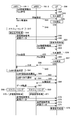
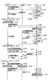
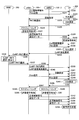
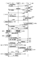
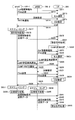
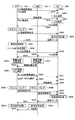
- FIG. 8 is a sequence showing a communication processing example (modification 1) in the first embodiment.
- the master base station 100-1 and the slave base station 100-2 transmit transmission data separately from a higher-level device (for example, MME (Mobility Management Entity, network)).
- a higher-level device for example, MME (Mobility Management Entity, network)
- transmission data is transmitted from the upper level only to the main master base station 100-1.
- the communication processing example shown in FIG. 7 is configured to only transmit the radio channel quality to each base station, whereas in the modification 1, the slave base station 100-2 as a slave is used. The wireless channel quality notified to is also notified to the master base station 100-1 via a network or the like.
- the terminal 200 selects a base station that performs CoMP transmission when a CoMP transmission request is made.
- the master base station 100-1 is the main master base station 100-1.
- a base station that performs CoMP transmission is selected.
- the master base station 100-1 and the slave base station 100-2 receive the pilot signals (S55, S56), measure and calculate the radio channel quality (for example, CQI) (S57), and the slave base station 100 -2 (S58).
- Slave base station 100-2 transmits the radio channel quality information obtained from terminal 200 to master base station 100-1 via the network (S59).
- the terminal 200 transmits the wireless channel quality information to the master base station 100-1 (S60).
- the master base station 100-1 performs CoMP transmission determination as described above (S61), and transmits a CoMP transmission execution notification to the slave base station 100-2 and the terminal 200 (S63, S64). Similarly, the master base station 100-1 transmits a CoMP-RNTI notification to the slave base station 100-2 and the terminal 200 (S64, S65). As a result, the slave base station 100-2 and the terminal 200 perform line setting from the obtained information (S66). In addition, the master base station 100-1 transfers data necessary for scheduling to the slave base station 100-2 (S67).
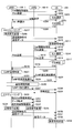
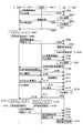
- FIG. 9 is a sequence illustrating a communication processing example (modification 2) in the first embodiment.
- the slave base station 100-2 in addition to the processing of the modified example 1, the master base station 100-1 Information (for example, Cell ID and slot number) is notified to the slave base station 100-2 and the terminal 200 (S107). Accordingly, the slave base station 100-2 can also perform scheduling using cell information or the like (S110).
- the master base station 100-1 Information for example, Cell ID and slot number
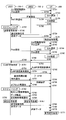
- FIG. 10 is a sequence illustrating a communication processing example (modification 3) in the first embodiment.
- Modification 3 only the master base station 100-1 is notified of the radio channel quality of the main master base station 100-1 and the radio channel quality of the slave base station 100-2 measured by the terminal 200 (S138). ).
- slave base station 100-2 has no data for the counterpart terminal (for example, terminal 200) that performs CoMP transmission, and is transmitted from the upper level only to main master base station 100-1. Has been. Therefore, in order to transmit data from slave base station 100-2, transmission data is transferred from master base station 100-1 to slave base station 100-2 (S146).
- Modification 3 scheduling is performed only at the main master base station 100-1 (S147).
- the master base station 100-1 notifies the transmission control information to the slave base station 100-2 (S148).
- transmission signal processing is performed by the master base station 100-1 and the slave base station 100-2 (S149, S150).
- the master base station 100-1 transmits a transmission control signal and transmission data to the terminal 200 (S151, S152), and the slave base station 100-2 transmits only the transmission data to the terminal 200. (S153).
- FIG. 11 is a sequence illustrating a communication processing example (Modification 4) in the first embodiment.
- the master base station 100-1 determines the necessity of CoMP transmission, etc. And it is determined whether or not transmission is possible.
- master base station 100-1 determines whether CoMP transmission is possible or not (S181).
- a request for execution of CoMP transmission is transmitted from the terminal 200 to the master base station 100-1 and the slave base station 100-2 (S182, S183).
- the master base station 100-1 performs CoMP transmission execution notification in response to the CoMP transmission execution request obtained from the terminal 200 (S184, S185).
- the master base station 100-1 notifies other cell information and the like to the slave base station (S189).
- FIG. 12 is a sequence illustrating a communication processing example (modification 5) in the first embodiment.
- the master base station 100-1 and the slave base station 100-2 are already synchronized.
- the synchronization is, for example, that the start timings of the slots constituting each radio frame match, the slot numbers match, the transmission frequencies of both match, etc. It is.
- at least the slot numbers need to match.
- a certain allowable range for example, a time difference of 0.1 msec or less or a frequency difference of 100 Hz or less may be used.
- the initial value of the scrambling code was calculated using equation (1).
- the CoMP-RNTI for example, 16 bits
- the (physical) cell ID N ID cell for example, 9 bits 0 to 503
- the slot number n s for example, 5 bits 0 to 19
- the transmission efficiency is better when the information (for example, control information) generally notified is smaller than the amount of data transmitted based on the information. Therefore, it is necessary to reduce the control information.
- the slave base station is set with a (physical) cell ID different from that of the master base station. Using this (physical) cell ID, a scrambling code is created and the data to be transmitted is scrambled.
- a scrambling code must be created using a physical cell ID of the master base station that is not the (physical) cell ID that is normally used. Processing occurs.
- the initial value of the scrambling code can be calculated without notifying the (physical) cell ID N ID cell and without using the (physical) cell ID of the master base station.
- the term of (physical) cell ID N ID cell in the value calculation formula is deleted. That is, in the second embodiment, the initial value of the scrambling code is calculated by the following equation (4).
- the amount of information 9 bits necessary for notification can be reduced, and the scrambling process in the base station and the terminal can be reduced.
- the term of the slot number is deleted from the scrambling code initial value calculation formula. That is, in the second embodiment, the term of (physical) cell ID in the scrambling code initial value calculation formula is deleted, but here, the slot number is deleted.
- the SFN System Frame Number
- the head timing of the SFN and the head timing of the slot and the slave base station (for example, slave base station) It is not guaranteed that the SFN and the start timing of the SFN coincide with the start timing of the slot.
- the slot numbers of the respective base stations may be different.
- the slot number of the main base station may be 0 and the slot number of the subordinate base station may be 5.
- the slot number is notified from the main base station to the subordinate base station. If the notified slot number is not used, the initial value of the scrambling code and the scrambling code itself are used. It can be the same between base stations. However, it is better that the control information to be notified is small as described above.
- the slave base station creates a scrambling code based on a slot number different from that of the master base station, and scrambles the data to be transmitted.
- a new scrambling code must be created using a slot number of the master base station that is not the slot number that is normally used. To do.
- the slot number of the calculation formula of the initial value Delete the n s term is calculated by the following equation (5).
- the amount of information required for the notification can be reduced by 5 bits, and the scrambling process in the base station and the terminal can be reduced.
- the initial value of the scrambling code is calculated without using the (physical) cell ID.
- the initial value of the scrambling code is calculated without using the slot number.
- the initial value of the scrambling code is calculated without using both the physical cell ID and the slot number.
- the initial value of the scrambling code is calculated using the following equation (6).
- the information amount 14 bits required for the notification can be reduced, and the scrambling process in the base station and the terminal can be reduced.
- the CoMP-RNTI is set by the host apparatus (MME) of the base station.
- the RNTI is issued by the RRC of the base station.
- MME host apparatus
- the CoMP-RNTI collides between the base stations. May be used.
- CoMP-RNTI is issued by the host device of each base station and centrally managed. That is, in the fifth embodiment, CoMP-RNTI can be managed so that no CoMP-RNTI collision occurs by issuing a CoMP-RNTI from a higher-level device of the base station.
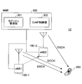
- FIG. 13 is a diagram illustrating a configuration example of a wireless communication system according to the fifth embodiment.
- the radio communication system 10B illustrated in FIG. 13 includes two base stations (eNBs) 100-1 and 100-2, a terminal (UE) 200, and an MME 300, as in the first embodiment described above.
- Base stations 100-1 and 100-2 transmit different data, and terminal 200 receives this (downlink direction).
- Terminal 200 can also transmit different data to base stations 100-1 and 100-2 (uplink direction). Both base stations 100-1 and 100-2 and terminal 200 can perform so-called CoMP communication.
- the base station 100-1 is a master base station
- the base station 100-2 is a slave base station.
- the MME 300 includes a mobility management unit 301 and a CoMP control unit 302.
- the mobility management unit 301 mainly performs mobility-related control (management), and manages location registration and the like of the base station.
- the mobility management unit 301 transmits mobility control information to the base stations 100-1, 100-2, and the like.
- the CoMP control unit 302 issues and manages CoMP-RNTI.
- the CoMP control unit 302 manages use / unuse of a plurality of CoMP-RNTIs. Specifically, for example, in response to a CoMP-RNTI request from a base station (for example, the master base station 100-1), the CoMP control unit 302 is unused from a plurality of CoMP-RNTIs or uses CoMP-RNTI. One of CoMP-RNTIs whose areas do not overlap is selected, and the selected CoMP-RNTI is transmitted to the requested base station.
- the MME 300 can also function as a data transfer and relay device, for example, as an S-GW (Serving Gate Way).
- the MME 300 when it is determined that CoMP transmission is necessary for transmission between a certain base station and a certain terminal, the MME 300 is requested to issue a CoMP-RNTI. Upon receiving the request, the MME 300 selects a CoMP-RNTI from CoMP-RNTIs not used by other base stations under the MME, and notifies the requested base station.
- the base station that has received the notification of CoMP-RNTI serves as a master base station (master base station 100-1) to a slave base station (slave base station 100-2) that performs CoMP transmission and the terminal 200. Then, CoMP-RNTI is notified and CoMP transmission is performed.
- a request for issuing CoMP-RNTI and identification of the master base station 100-1 and the slave base station 100-2 are sent to the MME 300. Notify information. Receiving the notification, the MME 300 selects the CoMP-RNTI as described above, and notifies the CoMP-RNTI to the master base station 100-1 and the slave base station 100-2.
- the master base station 100-1 Upon receiving the CoMP-RNTI notification, the master base station 100-1 notifies the CoMP-RNTI to the terminal 200 that performs CoMP transmission, and performs CoMP transmission.
- the CoMP control unit 302 of the MME 300 manages use / unuse of a plurality of CoMP-RNTIs and which base station is using the CoMP-RNTIs.
- the base station determines the necessity for CoMP transmission, but the terminal 200 determines the necessity for CoMP transmission, notifies the base station of the request for CoMP transmission, and notifies the base station.
- the received base station may request the MME 300 to issue CoMP-RNTI.
- CoMP-RNTI does not collide.
- the present invention is not limited to this. It is also possible to issue and manage.
- FIG. 14 is a diagram illustrating a block configuration example of a master base station according to the fifth embodiment.
- the master base station 100-1B shown in FIG. 14 includes an antenna unit 101, a reception radio unit 102, a demodulation / decoding unit 103, a radio channel quality information extraction unit 104, a scheduler 105, and a CoMP communication request signal extraction unit 106.
- the radio network controller 109 when the CoMP transmission is to be performed, the radio network controller 109 requests the MME 300 that is a higher-level device to allocate a CoMP-RNTI (CoMP-RNTI request). . Further, upon receiving the notification of CoMP-RNTI from the MME 300, the radio network controller 109 notifies the slave base station 100-1 and the terminal 200 of CoMP-RNTI.
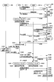
- FIG. 15 is a sequence illustrating an exemplary communication process in the fifth embodiment.
- terminal (UE) 200 is located in an area where communication connection is possible to both master base station (eNB1) 100-1 and slave base station (eNB2) 100-2.
- the MME 300 is provided as a host device of the base stations 100-1 and 100-2.
- the main difference between the fifth embodiment shown in FIG. 15 and the first embodiment described above is that the master base station 100-1 (master base station 100-1B in FIG. 14) acquires the CoMP-RNTI from the MME 300. is doing.
- the terminal 200 requests the master base station 100-1 to perform CoMP transmission with the slave base station 100-2 (S255). Thereafter, the master base station 100-1 requests CoMP-RNTI from the MME 300 (S256). Thereafter, as described above, the MME 300 selects and allocates the CoMP-RNTI (S257), and notifies the requested master base station 100-1 of the allocated CoMP-RNTI (S258).
- the master base station 100-1 notifies the CoMP-RNTI to the slave base station 100-2 and the terminal 200 based on the CoMP-RNTI obtained from the MME 300 (S262, S263).
- FIG. 16 is a sequence illustrating a communication processing example (modification 1) in the fifth embodiment.
- the main difference between the first modification shown in FIG. 16 and the communication processing example shown in FIG. 15 described above is shown in the first modification in the first embodiment described above and FIG.
- This is the same as the difference from the communication processing example. That is, in the communication processing example shown in FIG. 15, the master base station 100-1 and the slave base station 100-2 transmit transmission data separately from the host device (for example, the MME 300), whereas the modification 1 In this case, transmission data is transmitted only from the master to the master base station 100-1. Further, in the CQI transmission, the communication processing example shown in FIG. 15 is configured to only transmit the radio channel quality to each base station, whereas in the first modification, the slave base station 100-2 is notified.
- the wireless channel quality is also notified to the master base station 100-1 via a network or the like. Further, in the communication processing example shown in FIG. 15, the terminal 200 selects a base station that performs CoMP transmission when a CoMP transmission request is made, whereas in the first modification, the master base station 100-1 performs CoMP transmission. Select the base station to perform.
- FIG. 17 is a sequence illustrating a communication processing example (modification 2) in the fifth embodiment.
- the MME 300 notifies the master base station 100-1 only of CoMP-RNTI, and the master base station 100-1 notifies the slave base station 100-2 and the terminal 200 of CoMP-RNTI.
- the MME 300 notifies the master base station 100-1 and the slave base station 100-2 of CoMP-RNTI (S337, S338). Therefore, master base station 100-1 notifies CoMP-RNTI only to terminal 200 (S339).
- the processes of S320 to S356 in FIG. 17 the processes other than the above-described steps are substantially the same as the processes in the above-described communication processing examples, and thus detailed description thereof is omitted here. .
- FIG. 18 is a sequence illustrating a communication processing example (modification 3) in the fifth embodiment.
- the main difference between the modified example 3 shown in FIG. 18 and the modified example 1 shown in FIG. 16 is the same as that of the modified example 2 described above.
- the MME 300 notifies the master base station 100-1 and the slave base station 100-2 of CoMP-RNTI (S384, S385). Therefore, master base station 100-1 notifies CoMP-RNTI only to terminal 200 (S386).
- control of uplink CoMP transmission is controlled by a main base station (master base station).
- the main base station gives a terminal permission for transmission.
- uplink pilots transmitted from each terminal are received, and uplink radio channel quality is measured and calculated.
- the base station uses the scheduler 105 in the first embodiment described above to select a terminal that permits uplink data transmission, a transmission method for uplink data transmission, and a radio resource to be used based on the uplink radio channel quality. select. Also, the base station creates a control signal based on the selected result and notifies the terminal of the control signal.
- the terminal that has received the control signal encodes and modulates data based on the received control signal and transmits it to the base station.
- the transmission side selects the transmission method
- the base station on the reception side selects the transmission method for terminal transmission.
- the base station requests the terminal to transmit a pilot in order to measure and calculate the radio channel quality. That is, when a certain terminal performs uplink CoMP transmission, the master base station notifies CoMP-RNTI to the terminal. Also, the terminal uses the notified CoMP-RNTI to calculate the initial value of the scrambling code as in the above-described embodiment, and subsequently generates the scrambling code. Further, the terminal scrambles transmission data using the generated scrambling code and transmits it.
- the main base station notifies the subordinate base station (slave base station) of the CoMP-RNTI notified to the terminal.
- the slave base station that has received the CoMP-RNTI notification and the notified master base station calculate the initial value of the scrambling code using the CoMP-RNTI, and then generate the scrambling code.
- the slave base station and the master base station use the generated scrambling code to descramble the information obtained by demodulating the received wave at each base station transmitted from the terminal, and for the descrambled information. Decrypt and get data.
- first to fifth embodiments can be used for CoMP-RNTI selection / setting and calculation of the initial value of the scrambling code, for example.
- FIG. 19 is a diagram illustrating a block configuration example of a master base station according to the sixth embodiment.
- a master base station 100-1C shown in FIG. 19 includes an antenna unit 101, a reception radio unit 102, a demodulation / decoding unit 103, a scheduler 105, a CoMP communication request signal extraction unit 106, a control unit 107, and a connection request.
- the scheduler 105 of the master base station 100-1C measures and calculates uplink radio channel quality in order to determine whether or not uplink CoMP transmission is possible. Therefore, scheduler 105 outputs a control signal generation instruction for requesting terminal 200C to transmit a pilot to control signal generation section 115.
- control signal creation unit 115 Upon receiving this, the control signal creation unit 115 creates a pilot transmission request control signal, encodes and modulates it, and transmits it to the terminal 200C.
- master base station 100-1C receives the pilot transmitted from terminal 200C, and radio channel quality measurement calculation section 118 measures and calculates uplink radio channel quality. Radio channel quality measurement calculation section 118 outputs the calculation result to control section 107.
- the control unit 107 uses the predetermined inter-base station interface (I / F) to measure the radio channel quality measured and calculated by another base station (for example, a slave base station) notified to the master base station 100-1C. Receive. Based on these radio channel qualities, the control unit 107 determines whether or not uplink CoMP can be performed and selects a slave base station that receives uplink CoMP transmission.
- I / F inter-base station interface
- control unit 107 notifies the radio channel control unit 109 that uplink CoMP transmission is to be performed, sets CoMP-RNTI, and outputs it to the scrambling code creation unit 112 and the system information creation unit 113. To do.
- the scrambling code creation unit 112 creates a scrambling code and outputs the created scrambling code to the demodulation / decoding unit 103.
- Demodulation / decoding section 103 performs descrambling on the data sent from terminal 200 to obtain data. Since the subsequent processing is the same as that in the above-described embodiment of downlink CoMP transmission, description thereof is omitted here.
- FIG. 20 is a diagram illustrating a block configuration example of a slave base station according to the sixth embodiment.
- the slave base station 100-2B shown in FIG. 20 includes an antenna unit 101, a reception radio unit 102, a demodulation / decoding unit 103, a scheduler 105, a CoMP communication request signal extraction unit 106, a control unit 107, and a scrambling unit. It includes a code creation unit 112, a transmission data buffer 114, a control signal creation unit 115, an encoding / modulation unit 116, a transmission radio unit 117, and a radio channel quality measurement calculation unit 118.
- the slave base station 100-2B measures and calculates the uplink radio channel quality in the radio channel quality measurement / calculation unit 118 in the same manner as the master base station 100-1C described above. Note that, in the sixth embodiment, since it is an uplink, data reception is the same as that of the master base station 100-1C. The difference is that the radio channel quality measurement calculation unit 118 in the slave base station 100-2B notifies the master base station 100-1C of the measured / calculated radio channel quality using a predetermined inter-base station interface (I / F). It is a point to do.
- I / F inter-base station interface
- the scrambling code creation unit 112 creates a scrambling code and outputs the created scrambling code to the demodulation / decoding unit 103.
- Demodulation / decoding section 103 performs descrambling on the data sent from terminal 200 to obtain data.
- FIG. 21 is a diagram illustrating a configuration example of a terminal according to the sixth embodiment.
- a terminal 200C illustrated in FIG. 21 includes an antenna unit 201, a reception radio unit 202, a demodulation / decoding unit 203, a calculation unit 204, a radio channel quality information creation unit 205, a scrambling code creation unit 208, and reception control. It has a signal extraction unit 209, an encoding / modulation unit 214, a transmission radio unit 215, a system information extraction unit 217, a transmission / reception control unit 218, and a pilot creation unit 219.
- Terminal 200C demodulates and decodes the signal notified from master base station 100-1C by demodulation / decoding section 203.
- system information extraction section 217 extracts a pilot transmission request control signal from the demodulated / decoded signal and outputs it to transmission / reception control section 218.
- the transmission / reception control unit 218 requests the pilot creation unit 219 to create a pilot.
- the pilot creation unit 219 creates a pilot. Thereafter, the pilot is encoded / modulated by the encoder / modulator 214 and transmitted to the master base station 100-1C and the slave base station 100-2B.
- the scrambling code creation unit 208 creates a scrambling code for scrambling the transmission data and outputs the scrambling code to the encoding / modulation unit 214.
- the encoding / modulation unit 214 scrambles transmission data using the generated scrambling code.
- the scrambled transmission data is transmitted to master base station 100-1C and slave base station 100-2B.
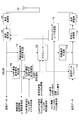
- FIG. 22 is a sequence illustrating an exemplary communication process in the sixth embodiment.
- the example illustrated in FIG. 22 illustrates an example of communication processing in which the master base station 100-1 determines whether to perform uplink CoMP (UL CoMP).
- UL CoMP uplink CoMP
- the terminal (UE) 200 includes both the master base station (eNB1) 100-1 (master base station 100-1C) and the slave base station (eNB2) 100-2 (slave base station 100-2B). It is assumed that it is located in an area where communication connection is possible.
- eNB1 master base station 100-1C
- eNB2 slave base station 100-2B
- the master base station 101-1 transmits an uplink (UL (Up Link)) transmission control signal (UL transmission control signal) to the terminal 200 after scheduling in the processing of S407 (S408).
- UL Up Link
- S407 S407
- the terminal 200 Upon receiving the UL transmission control signal, the terminal 200 performs transmission signal processing (S409), and transmits transmission data to the master base station 100-1 (S410). Thereafter, the master base station 100-1 performs uplink CoMP (UL CoMP) transmission determination (S412) and performs terminal transmission signal processing (S411). In addition, master base station 100-1 notifies terminal 200 of a pilot transmission request (S412).
- UL CoMP uplink CoMP
- terminal 200 Based on the pilot transmission request from master base station 100-1, terminal 200 creates a pilot by pilot creation section 219 and transmits the pilot to master base station 100-1 and slave base station 100-2 (S413, S414).
- the master base station 100-1 and the slave base station 100-2 perform wireless channel quality measurement (S416, S417).
- slave base station 100-2 transmits radio channel quality (for example, CQI) to master base station 100-1.
- Master base station 100-1 selects a cell to perform CoMP based on the radio channel quality obtained in S416 and S418.
- the master base station 100-1 notifies the execution target base station (for example, the slave base station 100-2) and the terminal 200 of uplink CoMP execution (S421, S422).
- the master base station 100-1 performs CoMP-RNTI notification to the target base station (for example, the slave base station 100-2) and the terminal 200 (S422, S422).
- line setting is performed between the slave base station 100-2 and the terminal 200 (S424).
- the master base station 100-1 notifies cell information and the like to the slave base station 100-2 (S425).
- scheduling is performed in the master base station 100-1 and the slave base station 100-2 (S426, S427), and the UL transmission control signal created from each is transmitted to the terminal 200 (S428, S429).
- the terminal 200 performs transmission signal processing (for example, scrambling) based on each UL transmission control signal (S430), and transmits transmission data to the master base station 100-1 and the slave base station 100-2.
- the master base station 100-1 and the slave base station 100-2 to which data is transmitted from the terminal respectively perform reception signal processing (for example, descrambling) (S433, S434).
- the slave base station 100-2 transfers the received signal processed data and the like to the master base station 100-1 (S435).
- FIG. 23 is a sequence illustrating a communication processing example (modification 1) in the sixth embodiment.
- FIG. 23 an example of communication processing in which the terminal 200 determines whether to perform uplink CoMP (UL CoMP) is illustrated.
- UL CoMP uplink CoMP
- the terminal 200 after transmitting the transmission data (S450), the terminal 200 performs uplink CoMP (UL CoMP) transmission determination (S452). Further, after the uplink determination, the terminal outputs an uplink CoMP transmission request to the target base station (for example, master base station 100-1) (S453).
- the target base station for example, master base station 100-1
- FIG. 24 is a sequence illustrating a communication processing example (modification 2) in the sixth embodiment.
- the example shown in FIG. 24 shows an example in which the master base station 100-1 determines whether to perform uplink CoMP (UL CoMP), and scheduling is performed only in the master base station 100-1.
- UL CoMP uplink CoMP
- the master base station 101-1 transmits the UL transmission control signal to the slave base station 100-2 and the terminal 200 after scheduling in the processing of S506 (S507, S508).
- the terminal 200 performs transmission signal processing of transmission data based on the received UL transmission control signal (S509), and transmits it to the master base station 100-1 and the slave base station 100-2 (S510, S511).
- the CoMP transmission scrambling code created with the initial value calculated by the above equation (6), the PDSCH scrambling code, and the PMCH scrambling code are uncorrelated (or orthogonal) to each other. Is desirable.
- the gold code which is a scrambling code is not completely uncorrelated between codes. That is, depending on the combination of the initial values, there is a possibility that correlation occurs and interference occurs.
- the three scrambling codes (CoMP transmission, PDSCH, and PMCH) described above are uncorrelated with each other, or the CoMP scrambling code is close to uncorrelated with the other two scrambling codes. It is desirable to change (shift) the CoMP scrambling code.
- the CoMP transmission scrambling code and other scrambling codes are made close to uncorrelated, thereby reducing interference and consequently improving transmission characteristics. it can.
- the interference is the two sides of the case where the interference is given and the case where the interference is received, if the transmission characteristic of CoMP transmission is improved, the transmission characteristic of the other normal data transmission or MBMS data transmission can also be improved.
- the CoMP offset is selected so that the CoMP transmission scrambling code and other scrambling codes are close to uncorrelated, that is, the interference is reduced, and the above-described (6 ) Add an offset term to the expression. As a result, the following equation (7) is obtained.
- the offset (CoMP_offset) may be notified to the terminal after being set as a variable at the base station, for example, or may be held as a fixed offset in the radio communication system. Further, the offset (CoMP_offset) may be notified as system information from the base station to the terminal.
- a scrambling code (hereinafter abbreviated as “code 1”) used for scrambling performed on the PDSCH that transmits individual data, and a PMCH that transmits MBMS data.
- Scrambling code (hereinafter abbreviated as “code 2”) used in scrambling
- code 3 a scrambling code used in scrambling performed in CoMP transmission. It should be uncorrelated (ie, orthogonal) and easily identifiable.
- the initial value must be selected so that the scrambling code has a low correlation.
- code 3 (or a plurality of codes 3) is extracted so that the scrambling performed in CoMP transmission has a smaller correlation with other scramblings, and an offset is set so that code 3 can be created.
- the above three codes (codes 1 to 3) are set.
- a CoMP transmission number CoMP number is set as transmission identification information for identifying a set for transmitting different data from a plurality of base stations to one terminal by switching simultaneously or in time. It may be used as the above-described offset or alternatively as the following equation (8).
- the CoMP-RNTI (CoMP-RNTI2) including the offset is used to correlate with other codes. Can be eliminated. In that case, the following equations (9) and (10) are obtained.
- FIG. 25 is a diagram illustrating a block configuration example of a master base station according to the seventh embodiment. 25 includes an antenna unit 101, a reception radio unit 102, a demodulation / decoding unit 103, a radio channel quality information extraction unit 104, a scheduler 105, a connection request signal extraction unit 108, A radio channel control unit 109, an RNTI setting unit 110, a scrambling code creation unit 112, a system information creation unit 113, a transmission data buffer 114, a control signal creation unit 115, an encoding / modulation unit 116, A transmission radio unit 117, a CoMP communication control unit 119, and an offset setting / storage unit 120 are included.
- the CoMP communication control unit 119 performs radio channel quality information obtained from the radio channel quality information extraction unit 104 and radio channel information obtained from another base station (adjacent base station). Based on the above, the implementation of CoMP communication is controlled.
- the CoMP communication control unit 119 outputs a CoMP execution notification to the scheduler 105 when performing CoMP.
- the radio network controller 109 acquires CoMP-RNTI or the like from the RNTI setting unit 110 based on the connection request signal from the connection request signal extraction unit 108 and outputs it to the system information creation unit 113.
- CoMP-RNTI or the like is set in the RNTI setting unit 110.
- the present invention is not limited to this.
- the CoMP-RNTI setting unit 111 sets the CoMP-RNTI. -RNTI may be obtained.
- the offset setting / storage unit 120 stores the offset described above.
- the system information creation unit 113 acquires offset information from the offset setting / storage unit 120 and outputs the offset information to the scrambling code creation unit 112.
- the scrambling code creation unit 112 creates a scrambling code for CoMP transmission using the above-described offset. Therefore, in the seventh embodiment, for example, it is possible to create a scrambling code having a small correlation with other scrambling.
- FIG. 26 is a diagram illustrating a block configuration example (modification 1) of the master base station according to the seventh embodiment.
- the master base station 100-1E shown in FIG. 26 includes an antenna unit 101, a reception radio unit 102, a demodulation / decoding unit 103, a radio channel quality information extraction unit 104, a scheduler 105, a connection request signal extraction unit 108, A radio channel control unit 109, an RNTI setting unit 110, a scrambling code creation unit 112, a system information creation unit 113, a transmission data buffer 114, a control signal creation unit 115, an encoding / modulation unit 116, A transmission wireless unit 117 and a CoMP communication control unit 119 are included.
- the radio network controller 109 acquires the CoMP-RNTI (CoMP-RNTI2) including the offset described above from the RNTI setting unit 110. Accordingly, the scrambling code creation unit 112 creates a scrambling code using CoMP-RNTI (CoMP-RNTI2) including an offset, thereby eliminating the correlation with other codes.
- CoMP-RNTI2 CoMP-RNTI2
- FIG. 27 is a diagram illustrating a configuration example of a terminal according to the seventh embodiment.
- blocks having substantially the same functions as those of the terminal 200B illustrated in FIG. 5 described above are denoted by the same reference numerals, and detailed description thereof is omitted here.
- 27 includes an antenna unit 201, a reception radio unit 202, a demodulation / decoding unit 203, a calculation unit 204, a radio channel quality information creation unit 205, a cell information extraction unit 206, a CoMP-RNTI.
- the terminal 200D illustrated in FIG. 27 includes an offset information extraction unit 220 as compared with the terminal 200D in the first modification of the first embodiment described above.
- the offset information extraction unit 220 extracts the above-described offset information from the reception signal output from the demodulation / decoding unit 203. Further, the offset information extraction unit 220 outputs the extracted offset information to the scrambling code generation unit 208.
- the scrambling code creation unit 208 creates an initial value of the scramble code based on the cell information (for example, including the cell number, CoMP-RNTI, slot number, and offset information), and sequentially creates the scrambling code. To do.
- the scrambling code creation unit 208 outputs the created scramble code to the demodulation / decoding unit 203.
- Demodulation / decoding section 203 descrambles the received data using the scrambling code obtained from scrambling code creation section 208.
- the CoMP transmission scrambling code and other scrambling codes are brought close to each other so as to be uncorrelated, and as a result, transmission characteristics can be reduced. Can be improved.
- FIG. 28 is a sequence illustrating an example of communication processing according to the seventh embodiment.
- the terminal (UE) 200 terminal 200D
- the terminal (UE) 200 terminal 200D
- eNB1 master base stations 100-1D and 100-1E
- eNB2 slave base station
- the main difference between the seventh embodiment shown in FIG. 28 and the first embodiment described above is that the master base station 100-1 notifies the slave base station 100-2 and the terminal 200 of the offset and the like. (S542, S543).
- the offset can be used to bring the CoMP transmission scrambling code and other scrambling codes close to uncorrelated, thereby reducing interference and consequently improving transmission characteristics. be able to.
- FIG. 29 is a sequence illustrating a communication processing example (modification 1) in the seventh embodiment.
- the master base station 100-1 to the slave base station 100 in the communication processing procedure for synchronization between base stations shown in the fifth modification of the first embodiment described above. -2 and the terminal 200 are notified of the offset and the like (S590, S591).
- FIG. 30 is a sequence illustrating a communication processing example (modification 2) in the seventh embodiment.
- CoMP including offsets from the master base station 100-1 to the slave base station 100-2 and the terminal 200.
- -RNTI CoMP-RNTI2
- S629, S630 notified
- the scrambling code for CoMP transmission and other scrambling codes are brought close to each other so as to be uncorrelated, thereby reducing interference.
- transmission characteristics can be improved.
- FIG. 31 is a sequence showing a communication processing example (modification 3) in the seventh embodiment.
- Modification 3 in the seventh embodiment shown in FIG. 31 is the same as the master base station 100-1 to the slave base station 100 in the communication processing procedure for performing inter-base station synchronization shown in Modification 5 in the first embodiment.
- -2 and the terminal 200 are notified of CoMP-RNTI (CoMP-RNTI2) including an offset (S677, S678).
- an eighth embodiment will be described.
- an offset is added based on an initial value calculation formula for PDSCH.
- the initial value of the scrambling code is offset so that the correlation between the scrambling code for CoMP and the scrambling code for PMSCH becomes small with respect to the scrambling code for PDSCH and the scrambling code for PMCH.
- a term of offset CoMP_offset 2 is added to the initial value calculation formula of the scrambling code for PDSCH as shown in the following formula (11).
- calculation of an initial value that enables creation of a CoMP scrambling code having a small correlation with the conventional scrambling code is set.
- CoMP scrambling codes having a small correlation with other PDSCH and PMCH scrambling codes can be created.
- the radio network controller 109 extracts the RNTI, Cell ID, etc. from the RNTI setting unit 110 and outputs the extracted information to the system information creation unit 113.
- the system information creation unit 113 acquires an offset from the offset setting / storage unit 120, and outputs the RNTI, Cell ID, offset, and the like to the scrambling code creation unit 112. Thereby, the scrambling code creation unit 112 can create a scrambling code by providing an offset to the initial value of the scrambling code using the offset.
- FIG. 32 is a sequence illustrating an example of communication processing according to the eighth embodiment.
- the terminal (UE) 200 terminal 200D
- the terminal (UE) 200 terminal 200D
- eNB1 master base stations 100-1D and 100-1E
- eNB2 slave base station
- the master base station 100-1 notifies the slave base station 100-2 and the terminal 200 of the RNTI or the like (S709, S710), and then notifies the offset or the like (S712, S713).
- FIG. 33 is a sequence illustrating a communication processing example (modification 1) in the eighth embodiment.
- the master base station 100-1 notifies the slave base station 100-2 and the terminal 200 of the RNTI or the like (S757, S758), and then notifies the offset or the like (S760, S761). ).
- the Cell ID term in the scrambling code initial value calculation formula is deleted and an offset is added. That is, in the ninth embodiment, the physical cell ID is deleted from the initial value calculation formula.
- a term of offset CoMP_offset 3 is added as shown in the following equation (12).
- radio network controller 109 extracts RNTI and the like from RNTI setting unit 110 and outputs the extracted information to system information creation unit 113. That is, in the ninth embodiment, the Cell ID is not notified.
- the scheduler 105 does not notify the scrambling code creation unit 112 of the slot number.
- the slot number and the physical cell ID are deleted from the scrambling code initial value calculation formula.
- a term of offset CoMP_offset 5 is added as shown in the following equation (14).
- the constant term q ⁇ 2 13 may be deleted. Also in this case, in order to lower the correlation as described above, a term of offset CoMP_offset 6 is added as shown in the following equation (15).
- the master base station 100-1D shown in FIG. 25 described above can be used as the base station apparatus configuration in the eleventh embodiment, but the present invention is not limited to this.
- a twelfth embodiment will be described.
- the above-described offset is also applied to uplink CoMP.
- the correlation with other scrambling codes is brought close to non-correlation using an offset even in the case of uplink CoMP shown in the sixth embodiment.
- interference can be reduced and, as a result, transmission characteristics can be improved.
- the configurations of the base station and the terminal in the twelfth embodiment can be, for example, the configurations of the base station and the terminal in the sixth embodiment described above, but are not limited thereto.
- FIG. 34 is a sequence illustrating an exemplary communication process in the twelfth embodiment.
- the master base station 100-1 determines whether to perform uplink CoMP (UL CoMP) is illustrated.
- UL CoMP uplink CoMP
- FIG. 35 is a sequence diagram illustrating a communication processing example (modification 1) according to the twelfth embodiment.
- the example illustrated in FIG. 35 illustrates an example of communication processing in which the master base station 100-1 determines whether to perform uplink CoMP (UL CoMP) as in FIG.
- UL CoMP uplink CoMP
- the master base station (eNB1) 100-1 notifies the slave base station (eNB2) 100-2 and the terminal (UE) 200 of CoMP-RNTI (CoMP-RNTI2) including an offset. (S842, S843).
- interference can be reduced by using an offset to make it uncorrelated with other scrambling codes, and as a result, transmission characteristics can be improved.
- processing can be reduced in a terminal or a base station.
- reduction of power consumption can be aimed at in a terminal or a base station.
- the initial value calculation process of the scrambling code in the base station and terminal which implements CoMP transmission can be reduced, for example.
- the communication process in the embodiment can be performed by a computer.
- the recording medium is a recording medium that records information optically, electrically, or magnetically, such as a CD-ROM, flexible disk, magneto-optical disk, etc., and information is electrically recorded, such as a ROM, flash memory, etc.
- Various types of recording media such as a semiconductor memory can be used.
Landscapes
- Engineering & Computer Science (AREA)
- Signal Processing (AREA)
- Computer Networks & Wireless Communication (AREA)
- Quality & Reliability (AREA)
- Mobile Radio Communication Systems (AREA)
Abstract
Le dispositif de station de base selon l'invention ayant une pluralité de cellules et qui conduit des communications sans fil avec un dispositif terminal a : un moyen servant à recevoir d'un autre dispositif de station de base des conditions de communication utilisées pour le traitement de signal pendant les communications sans fil avec le dispositif terminal ; un moyen qui décale les communications coopératives, les communications sans fil étant conduites avec le dispositif terminal en coopération avec l'autre dispositif de station de base, quand les conditions de communications reçues de l'autre dispositif de station de base sont reçues ; et un moyen qui, pendant les communications coopératives, conduit des communications sans fil avec le dispositif terminal en utilisant les conditions de communications reçues de l'autre dispositif de station de base.
Priority Applications (7)
| Application Number | Priority Date | Filing Date | Title |
|---|---|---|---|
| JP2013507018A JP5962650B2 (ja) | 2011-03-31 | 2011-03-31 | 通信システム、基地局装置、端末装置、及び通信方法 |
| PCT/JP2011/058355 WO2012132016A1 (fr) | 2011-03-31 | 2011-03-31 | Système de communications, dispositif de station de base, dispositif terminal, et procédé de communications |
| EP11862589.6A EP2693817A4 (fr) | 2011-03-31 | 2011-03-31 | Système de communications, dispositif de station de base, dispositif terminal, et procédé de communications |
| KR1020137025825A KR101512261B1 (ko) | 2011-03-31 | 2011-03-31 | 통신 시스템, 기지국 장치, 단말 장치 및 통신 방법 |
| CN201180069840.8A CN103460771B (zh) | 2011-03-31 | 2011-03-31 | 通信系统、基站装置、终端装置以及通信方法 |
| TW100126589A TWI482474B (zh) | 2011-03-31 | 2011-07-27 | A communication system, a base station apparatus, a terminal apparatus, and a communication method |
| US14/030,571 US20140016565A1 (en) | 2011-03-31 | 2013-09-18 | Communication system, base station apparatus, terminal apparatus, and communication method |
Applications Claiming Priority (1)
| Application Number | Priority Date | Filing Date | Title |
|---|---|---|---|
| PCT/JP2011/058355 WO2012132016A1 (fr) | 2011-03-31 | 2011-03-31 | Système de communications, dispositif de station de base, dispositif terminal, et procédé de communications |
Related Child Applications (1)
| Application Number | Title | Priority Date | Filing Date |
|---|---|---|---|
| US14/030,571 Continuation US20140016565A1 (en) | 2011-03-31 | 2013-09-18 | Communication system, base station apparatus, terminal apparatus, and communication method |
Publications (1)
| Publication Number | Publication Date |
|---|---|
| WO2012132016A1 true WO2012132016A1 (fr) | 2012-10-04 |
Family
ID=46929834
Family Applications (1)
| Application Number | Title | Priority Date | Filing Date |
|---|---|---|---|
| PCT/JP2011/058355 Ceased WO2012132016A1 (fr) | 2011-03-31 | 2011-03-31 | Système de communications, dispositif de station de base, dispositif terminal, et procédé de communications |
Country Status (7)
| Country | Link |
|---|---|
| US (1) | US20140016565A1 (fr) |
| EP (1) | EP2693817A4 (fr) |
| JP (1) | JP5962650B2 (fr) |
| KR (1) | KR101512261B1 (fr) |
| CN (1) | CN103460771B (fr) |
| TW (1) | TWI482474B (fr) |
| WO (1) | WO2012132016A1 (fr) |
Cited By (8)
| Publication number | Priority date | Publication date | Assignee | Title |
|---|---|---|---|---|
| JP2014120779A (ja) * | 2012-12-12 | 2014-06-30 | Nippon Telegr & Teleph Corp <Ntt> | 分散無線通信基地局システムの通信方式及び分散無線通信基地局システム |
| WO2015027522A1 (fr) * | 2013-09-02 | 2015-03-05 | 华为技术有限公司 | Procédé et appareil de transmission collaboratif de liaison montante |
| WO2015111098A1 (fr) * | 2014-01-24 | 2015-07-30 | 富士通株式会社 | Procédé de communication sans fil, système de communication sans fil, station de base et station sans fil |
| JP2015233247A (ja) * | 2014-06-10 | 2015-12-24 | 富士通株式会社 | 通信システム及び基地局 |
| JP2017519396A (ja) * | 2014-06-17 | 2017-07-13 | ホアウェイ・テクノロジーズ・カンパニー・リミテッド | ユーザ装置、アクセスノード装置、中央ネットワークコントローラ、および対応する方法 |
| JP2017528942A (ja) * | 2014-07-09 | 2017-09-28 | テレフオンアクチーボラゲット エルエム エリクソン(パブル) | ワイヤレスデバイスからの伝送のCoMP受信を実行するためのネットワークノードおよびネットワークノードにおける方法 |
| JP2017216740A (ja) * | 2017-08-10 | 2017-12-07 | 富士通株式会社 | ネットワーク構成方法、装置及びシステム |
| US10292085B2 (en) | 2013-08-05 | 2019-05-14 | Fujitsu Connected Technologies Limited | Network configuration method and apparatus and system |
Families Citing this family (10)
| Publication number | Priority date | Publication date | Assignee | Title |
|---|---|---|---|---|
| US8792924B2 (en) * | 2011-05-06 | 2014-07-29 | Futurewei Technologies, Inc. | System and method for multi-cell access |
| JP5760685B2 (ja) * | 2011-05-20 | 2015-08-12 | ソニー株式会社 | 通信制御装置、通信制御方法、プログラムおよび通信システム |
| GB2499674B (en) * | 2012-02-27 | 2014-03-26 | Broadcom Corp | Method and apparatus for coordinated multi-point operations |
| KR20130128028A (ko) * | 2012-05-16 | 2013-11-26 | 삼성전자주식회사 | 통신 시스템에서 협업 통신을 수행하는 장치 및 방법 |
| US20150078297A1 (en) * | 2013-09-17 | 2015-03-19 | Industrial Technology Research Institute | Method of resource allocation for device to device communication, user equipment using the same and base station using the same |
| US10142799B2 (en) | 2014-08-19 | 2018-11-27 | Qualcomm Incorporated | Multicasting traffic using multi-connectivity |
| JP6361739B2 (ja) | 2014-11-07 | 2018-07-25 | 日本電気株式会社 | 無線通信システム、基地局、通信方法 |
| WO2017073006A1 (fr) * | 2015-10-29 | 2017-05-04 | パナソニックIpマネジメント株式会社 | Dispositif de communication, terminal et procédé de communication |
| CN106954271B (zh) * | 2016-01-07 | 2019-09-13 | 工业和信息化部电信研究院 | 一种下行数据信道发送方法、装置和系统 |
| JP2019115004A (ja) * | 2017-12-26 | 2019-07-11 | シャープ株式会社 | 基地局装置、端末装置および通信方法 |
Citations (9)
| Publication number | Priority date | Publication date | Assignee | Title |
|---|---|---|---|---|
| JP2004531945A (ja) | 2001-04-25 | 2004-10-14 | コーニンクレッカ フィリップス エレクトロニクス エヌ ヴィ | 無線通信システム |
| JP2006311475A (ja) | 2005-03-31 | 2006-11-09 | Ntt Docomo Inc | 制御装置、移動局および移動通信システム並びに制御方法 |
| JP2008092379A (ja) | 2006-10-03 | 2008-04-17 | Ntt Docomo Inc | 下りリンクスクランブル方法および基地局装置 |
| JP2009516936A (ja) | 2006-04-20 | 2009-04-23 | ミツビシ・エレクトリック・リサーチ・ラボラトリーズ・インコーポレイテッド | 協調、マルチユーザ、多入力多出力のネットワークにおいて信号を送受信する方法 |
| JP2010146617A (ja) | 2008-12-17 | 2010-07-01 | Panasonic Corp | 光ピックアップ装置及び光ディスク装置 |
| WO2010125738A1 (fr) * | 2009-04-28 | 2010-11-04 | 三菱電機株式会社 | Système de communication mobile |
| WO2010146617A1 (fr) * | 2009-06-15 | 2010-12-23 | 富士通株式会社 | Système de communication sans fil, dispositif de station de base, dispositif terminal et procédé de communication sans fil dans un système de communication sans fil |
| JP2011001458A (ja) | 2009-06-18 | 2011-01-06 | Mitsubishi Chemicals Corp | ポリカーボネート樹脂、それを用いた電子写真感光体、及びポリカーボネート樹脂の製造方法 |
| WO2011001458A1 (fr) * | 2009-06-29 | 2011-01-06 | 富士通株式会社 | Système de communication sans fil, appareil de station de base, appareil de terminal et procédé de communication sans fil pour un système de communication sans fil |
Family Cites Families (24)
| Publication number | Priority date | Publication date | Assignee | Title |
|---|---|---|---|---|
| KR100635013B1 (ko) * | 2004-12-03 | 2006-10-16 | 한국전자통신연구원 | 다중 셀 환경에서의 동기식 ofdm 수신 장치 및 그방법 |
| KR20080015231A (ko) * | 2006-08-14 | 2008-02-19 | 삼성전자주식회사 | 통신 시스템에서 신호 송수신 장치 및 방법 |
| WO2008053932A1 (fr) * | 2006-10-31 | 2008-05-08 | Kddi Corporation | Appareil formant station de base radio, et appareil de terminal radio |
| CN101102125B (zh) * | 2007-08-09 | 2012-06-13 | 中兴通讯股份有限公司 | 一种辅同步信道加扰方法及其对应小区搜索方式 |
| US8509162B2 (en) * | 2008-02-13 | 2013-08-13 | Qualcomm Incorporated | System and method for scheduling over multiple hops |
| US8559351B2 (en) * | 2008-08-01 | 2013-10-15 | Qualcomm Incorporated | Dedicated reference signal design for network MIMO |
| WO2010018908A1 (fr) * | 2008-08-11 | 2010-02-18 | Lg Electronics Inc. | Procédé d'exploitation d'une station relais dans un système de communication sans fil |
| WO2010068011A2 (fr) * | 2008-12-08 | 2010-06-17 | Lg Electronics Inc. | Procédé d'émission et de réception d'un canal physique partagé pour liaisons descendantes dans un système de radiocommunications |
| US20100157826A1 (en) * | 2008-12-19 | 2010-06-24 | Telefonaktiebolaget Lm | Local communication between mobile stations via one or more relay stations |
| US9094167B2 (en) * | 2009-02-02 | 2015-07-28 | Samsung Electronics Co., Ltd. | System and method for multi-user and multi-cell MIMO transmissions |
| KR101729548B1 (ko) * | 2009-03-06 | 2017-05-02 | 엘지전자 주식회사 | CoMP 기법이 적용된 무선 통신 시스템에서 채널 품질 정보 송신 방법 및 이를 위한 장치 |
| US8873505B2 (en) * | 2009-03-12 | 2014-10-28 | Interdigital Patent Holdings, Inc. | Method and apparatus for performing component carrier-specific reconfiguration |
| JP2010258693A (ja) * | 2009-04-23 | 2010-11-11 | Sharp Corp | マルチキャリア送信装置、受信装置、通信システム、送信方法、受信方法及びプログラム |
| CN101931485B (zh) * | 2009-06-19 | 2014-02-12 | 北京三星通信技术研究有限公司 | 一种专用参考信号生成方法和装置 |
| KR101642311B1 (ko) * | 2009-07-24 | 2016-07-25 | 엘지전자 주식회사 | CoMP 참조신호 송수신 방법 |
| US20110032838A1 (en) * | 2009-08-04 | 2011-02-10 | Qualcomm Incorporated | Mitigation of crs misalignment in coordinated multipoint communications |
| US8300587B2 (en) * | 2009-08-17 | 2012-10-30 | Nokia Corporation | Initialization of reference signal scrambling |
| US20110217985A1 (en) * | 2009-09-28 | 2011-09-08 | Qualcomm Incorporated | Predictive short-term channel quality reporting utilizing reference signals |
| US8923905B2 (en) * | 2009-09-30 | 2014-12-30 | Qualcomm Incorporated | Scrambling sequence initialization for coordinated multi-point transmissions |
| US8437300B2 (en) * | 2009-10-12 | 2013-05-07 | Samsung Electronics Co., Ltd | Method and system of multi-layer beamforming |
| US8948028B2 (en) * | 2009-10-13 | 2015-02-03 | Qualcomm Incorporated | Reporting of timing information to support downlink data transmission |
| US20110317656A1 (en) * | 2009-12-23 | 2011-12-29 | Qualcomm Incorporated | Cluster-specific reference signals for communication systems with multiple transmission points |
| CA2789441C (fr) * | 2010-02-12 | 2016-12-13 | Research In Motion Limited | Signal de reference pour la mise en oeuvre coordonnee d'un reseau multipoint |
| WO2012096599A1 (fr) * | 2011-01-13 | 2012-07-19 | Telefonaktiebolaget L M Ericsson (Publ) | Station de base modulaire |
-
2011
- 2011-03-31 WO PCT/JP2011/058355 patent/WO2012132016A1/fr not_active Ceased
- 2011-03-31 CN CN201180069840.8A patent/CN103460771B/zh not_active Expired - Fee Related
- 2011-03-31 KR KR1020137025825A patent/KR101512261B1/ko not_active Expired - Fee Related
- 2011-03-31 JP JP2013507018A patent/JP5962650B2/ja not_active Expired - Fee Related
- 2011-03-31 EP EP11862589.6A patent/EP2693817A4/fr not_active Withdrawn
- 2011-07-27 TW TW100126589A patent/TWI482474B/zh not_active IP Right Cessation
-
2013
- 2013-09-18 US US14/030,571 patent/US20140016565A1/en not_active Abandoned
Patent Citations (9)
| Publication number | Priority date | Publication date | Assignee | Title |
|---|---|---|---|---|
| JP2004531945A (ja) | 2001-04-25 | 2004-10-14 | コーニンクレッカ フィリップス エレクトロニクス エヌ ヴィ | 無線通信システム |
| JP2006311475A (ja) | 2005-03-31 | 2006-11-09 | Ntt Docomo Inc | 制御装置、移動局および移動通信システム並びに制御方法 |
| JP2009516936A (ja) | 2006-04-20 | 2009-04-23 | ミツビシ・エレクトリック・リサーチ・ラボラトリーズ・インコーポレイテッド | 協調、マルチユーザ、多入力多出力のネットワークにおいて信号を送受信する方法 |
| JP2008092379A (ja) | 2006-10-03 | 2008-04-17 | Ntt Docomo Inc | 下りリンクスクランブル方法および基地局装置 |
| JP2010146617A (ja) | 2008-12-17 | 2010-07-01 | Panasonic Corp | 光ピックアップ装置及び光ディスク装置 |
| WO2010125738A1 (fr) * | 2009-04-28 | 2010-11-04 | 三菱電機株式会社 | Système de communication mobile |
| WO2010146617A1 (fr) * | 2009-06-15 | 2010-12-23 | 富士通株式会社 | Système de communication sans fil, dispositif de station de base, dispositif terminal et procédé de communication sans fil dans un système de communication sans fil |
| JP2011001458A (ja) | 2009-06-18 | 2011-01-06 | Mitsubishi Chemicals Corp | ポリカーボネート樹脂、それを用いた電子写真感光体、及びポリカーボネート樹脂の製造方法 |
| WO2011001458A1 (fr) * | 2009-06-29 | 2011-01-06 | 富士通株式会社 | Système de communication sans fil, appareil de station de base, appareil de terminal et procédé de communication sans fil pour un système de communication sans fil |
Non-Patent Citations (6)
| Title |
|---|
| "Feasibility study for further Advancements for E- UTRA (LTE-Advanced) (Release 9", TR36.912 V9.3.0 |
| "Further Advancement for E-UTRA Physical Layer Aspects (Release 9", TR36.814 V 9.0.0 |
| "Further Advancement for E-UTRA Physical Layer Aspects (Release 9", TR36.814 V9.0.0 |
| "Further Advancements for E-UTRA Physical Layer Aspects (Release 9", TR36.814 V9.0.0 |
| "Physical Channel and Modulation (Release 9", TS36.211 V9.1.0 |
| See also references of EP2693817A4 |
Cited By (12)
| Publication number | Priority date | Publication date | Assignee | Title |
|---|---|---|---|---|
| JP2014120779A (ja) * | 2012-12-12 | 2014-06-30 | Nippon Telegr & Teleph Corp <Ntt> | 分散無線通信基地局システムの通信方式及び分散無線通信基地局システム |
| US10292085B2 (en) | 2013-08-05 | 2019-05-14 | Fujitsu Connected Technologies Limited | Network configuration method and apparatus and system |
| US10932178B2 (en) | 2013-08-05 | 2021-02-23 | Fujitsu Connected Technologies Limited | Network configuration method and apparatus and system |
| US11546823B2 (en) | 2013-08-05 | 2023-01-03 | Fujitsu Connected Technologies Limited | Network configuration method and apparatus and system |
| WO2015027522A1 (fr) * | 2013-09-02 | 2015-03-05 | 华为技术有限公司 | Procédé et appareil de transmission collaboratif de liaison montante |
| WO2015111098A1 (fr) * | 2014-01-24 | 2015-07-30 | 富士通株式会社 | Procédé de communication sans fil, système de communication sans fil, station de base et station sans fil |
| JPWO2015111098A1 (ja) * | 2014-01-24 | 2017-03-23 | 富士通株式会社 | 無線通信方法、無線通信システム、基地局、および無線局 |
| JP2015233247A (ja) * | 2014-06-10 | 2015-12-24 | 富士通株式会社 | 通信システム及び基地局 |
| JP2017519396A (ja) * | 2014-06-17 | 2017-07-13 | ホアウェイ・テクノロジーズ・カンパニー・リミテッド | ユーザ装置、アクセスノード装置、中央ネットワークコントローラ、および対応する方法 |
| US10477496B2 (en) | 2014-06-17 | 2019-11-12 | Huawei Technologies Co., Ltd. | User device, access node device, central network controller and corresponding methods |
| JP2017528942A (ja) * | 2014-07-09 | 2017-09-28 | テレフオンアクチーボラゲット エルエム エリクソン(パブル) | ワイヤレスデバイスからの伝送のCoMP受信を実行するためのネットワークノードおよびネットワークノードにおける方法 |
| JP2017216740A (ja) * | 2017-08-10 | 2017-12-07 | 富士通株式会社 | ネットワーク構成方法、装置及びシステム |
Also Published As
| Publication number | Publication date |
|---|---|
| US20140016565A1 (en) | 2014-01-16 |
| KR20130128006A (ko) | 2013-11-25 |
| CN103460771A (zh) | 2013-12-18 |
| EP2693817A1 (fr) | 2014-02-05 |
| JP5962650B2 (ja) | 2016-08-03 |
| TWI482474B (zh) | 2015-04-21 |
| CN103460771B (zh) | 2017-03-15 |
| JPWO2012132016A1 (ja) | 2014-07-24 |
| KR101512261B1 (ko) | 2015-04-17 |
| EP2693817A4 (fr) | 2014-09-10 |
| TW201240411A (en) | 2012-10-01 |
Similar Documents
| Publication | Publication Date | Title |
|---|---|---|
| JP5962650B2 (ja) | 通信システム、基地局装置、端末装置、及び通信方法 | |
| US9461785B2 (en) | Control signaling method and apparatus in a coordinated multi-point system | |
| US9629164B2 (en) | Radio communication system, base station apparatus, terminal apparatus, and radio communication method in radio communication system | |
| CN104247282B (zh) | 移动终端处使用信令传输的信息的小区间干扰消除 | |
| KR101596543B1 (ko) | 하향링크 comp 전송을 위한 프레임 구조 및 제어 시그널링 | |
| KR101571461B1 (ko) | 기준 신호 시퀀스 구성 방법 및 네트워크 기기 | |
| JP6325249B2 (ja) | ユーザ端末及び無線通信方法 | |
| US9788324B2 (en) | Carrier status indication method and device | |
| KR101387995B1 (ko) | 다운링크 중첩된 라디오 신호, 기지국 및 그에 대한 이용자 단말에 의한 다운링크 통신을 위한 방법 | |
| CN104205691A (zh) | 用于增强的扰码序列的方法和装置 | |
| JP2010258612A (ja) | 無線通信システム、基地局装置、制御方法、プログラムおよび記録媒体 | |
| EP3639595B1 (fr) | Procédés et appareils de configuration de signaux de référence | |
| CN102355292A (zh) | 参数传输方法及装置、参数生成方法及装置 | |
| US20200099465A1 (en) | Methods and apparatuses for reference signal configuration | |
| JP6111270B2 (ja) | 移動通信システム、通信制御方法、基地局、ユーザ端末及びプロセッサ | |
| WO2014098187A1 (fr) | Système de communication mobile, procédé de commande de communication, station de base, terminal d'utilisateur, et processeur | |
| JP2014143606A (ja) | 無線通信システム、無線通信方法、無線基地局及びユーザ端末 | |
| WO2018033071A1 (fr) | Procédé et appareil de commande collaborative parmi des points d'accès sans fil | |
| CN114342506B (zh) | 用于多trp的pdsch加扰方案 | |
| JP5704275B2 (ja) | 無線通信システム、基地局装置、端末装置、及び無線通信システムにおける無線通信方法 | |
| CN103906254B (zh) | 信令信息交换与映射的方法及装置 | |
| WO2014181484A1 (fr) | Systeme de communication, procede de communication, terminal utilisateur, procede de commande, station de base de connexion, station de base de cooperation, et systeme de communication sans fil | |
| JP5605471B2 (ja) | 無線通信システム、基地局装置、端末装置、及び無線通信システムにおける無線通信方法 |
Legal Events
| Date | Code | Title | Description |
|---|---|---|---|
| 121 | Ep: the epo has been informed by wipo that ep was designated in this application |
Ref document number: 11862589 Country of ref document: EP Kind code of ref document: A1 |
|
| ENP | Entry into the national phase |
Ref document number: 2013507018 Country of ref document: JP Kind code of ref document: A |
|
| ENP | Entry into the national phase |
Ref document number: 20137025825 Country of ref document: KR Kind code of ref document: A |
|
| NENP | Non-entry into the national phase |
Ref country code: DE |