WO2012132020A1 - Système de traitement d'informations, appareil de traitement d'informations et circuit intégré - Google Patents
Système de traitement d'informations, appareil de traitement d'informations et circuit intégré Download PDFInfo
- Publication number
- WO2012132020A1 WO2012132020A1 PCT/JP2011/058363 JP2011058363W WO2012132020A1 WO 2012132020 A1 WO2012132020 A1 WO 2012132020A1 JP 2011058363 W JP2011058363 W JP 2011058363W WO 2012132020 A1 WO2012132020 A1 WO 2012132020A1
- Authority
- WO
- WIPO (PCT)
- Prior art keywords
- power
- integrated circuit
- information processing
- instruction
- circuit
- Prior art date
- Legal status (The legal status is an assumption and is not a legal conclusion. Google has not performed a legal analysis and makes no representation as to the accuracy of the status listed.)
- Ceased
Links
Images


Classifications
-
- G—PHYSICS
- G06—COMPUTING OR CALCULATING; COUNTING
- G06F—ELECTRIC DIGITAL DATA PROCESSING
- G06F1/00—Details not covered by groups G06F3/00 - G06F13/00 and G06F21/00
- G06F1/26—Power supply means, e.g. regulation thereof
-
- G—PHYSICS
- G06—COMPUTING OR CALCULATING; COUNTING
- G06F—ELECTRIC DIGITAL DATA PROCESSING
- G06F9/00—Arrangements for program control, e.g. control units
- G06F9/06—Arrangements for program control, e.g. control units using stored programs, i.e. using an internal store of processing equipment to receive or retain programs
- G06F9/44—Arrangements for executing specific programs
- G06F9/4401—Bootstrapping
Definitions
- the present invention relates to an information processing system, a system management apparatus, and an integrated circuit that execute a power-on sequence.
- a large-scale server system having a large number of servers is provided with a system management apparatus having a Management Board (MMB), and the MMB performs system management collectively.
- system management refers to power supply and clock settings, system resets, register settings for each operation, and the like.
- the MMB uses an external interface to control the Large Scale Integration (LSI) and VR (DC-DC converter) installed in each server.
- LSI Large Scale Integration
- VR DC-DC converter
- the MMB performs power supply and clock settings, system resets, operation register settings, and the like for each server LSI and power supply circuit.
- the scale of server systems has increased, and objects such as servers and LSIs controlled by MMB have increased. Therefore, there is a problem that the startup time of the system increases because the number of objects set by the MMB increases when the system is started up.
- An object of the present invention is to shorten the time of the system power-on sequence.
- An information processing system includes a plurality of information processing apparatuses having an integrated circuit and a system board equipped with a power supply circuit that supplies power to the integrated circuit, and a system that transmits a power-on instruction to the plurality of information processing apparatuses A management device.
- Each integrated circuit of the plurality of information processing devices when receiving the power-on instruction, instructs the power supply circuit to adjust the voltage.
- the system power-on sequence time can be shortened.
- FIG. 1 is a configuration diagram of a system according to an embodiment. It is a figure which shows the power-on sequence of the system which concerns on embodiment. It is a detailed block diagram of the power supply circuit and LSI which concern on embodiment. It is a figure which shows the power-on sequence of LSI which concerns on embodiment. It is a figure which shows the power-on sequence of LSI which concerns on embodiment. It is a detailed flowchart of a temporary stop process. It is a figure which shows the structure regarding the register setting of LSI which concerns on embodiment. It is a figure which shows the writing of the register
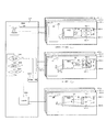
- FIG. 1 is a configuration diagram of a system according to an embodiment.
- the system management apparatus 201 and the server 301 are connected by a serial interface (for example, Inter-Integrated Circuit (I2C)).
- the system management apparatus 201 includes a management board (MMB) 210.
- the MMB 210 performs a power-on instruction for the server 301, specifies the server 301 that failed to power on, and the like.
- the MMB 210 includes a central processing unit (CPU) 211, a read only memory (ROM) 212, a random access memory (RAM) 213, an interface (IF) control unit 214, a power supply control unit 215, and a storage unit 216.
- the CPU 211 reads a program stored in the ROM 212 and executes the program.
- the ROM 212 is a storage unit that stores programs for performing various processes described later.
- the RAM 213 is a storage unit that temporarily stores data used in various processes.
- the IF control unit 214 controls an interface between the MMB 210 and the server 320.
- the IF control unit 214 reads / writes data from / to the storage unit 216.
- the power control unit 215 outputs a power-on instruction to the power-on target server 301 based on the contents of the storage unit 216 and the instruction from the CPU 211.
- the storage unit 216 stores information indicating a server that performs power-on, information indicating completion of power-on of the server, information indicating interruption, and the like.
- the storage unit 216 is, for example, a register. When receiving a Ready response or an interrupt response from the server 301, the storage unit 216 stores information indicating power-on completion of each server 320, information indicating an interrupt, and the like.
- MB Management Board
- SB System Board
- the MB 310 includes an IF control unit 314, a power supply control unit 315, a storage unit 316, and a signal output circuit 317.
- the IF control unit 314 controls an interface between the MB 310 and the MMB 210, and between the MB 310 and the SB 320. Further, the IF control unit 314 reads / writes data from / to the storage unit 316.
- the power control unit 315 Based on the contents of the storage unit 316 (for example, information indicating the SB 320 or LSI 323 to be powered on) and the instruction from the power control unit 215, the power control unit 315 instructs the SB 320 to be powered on. Is output.
- the storage unit 316 stores information indicating the SB 320 that performs power-on from the MMB 210, information indicating completion of power-on of each SB 320 from the SB 320, information indicating an interrupt, and the like.
- the storage unit 316 is, for example, a register.
- the storage unit 316 stores information indicating the power-on completion of the SB 320 that transmitted the Ready response when receiving the Ready response from the SB 320, and stores information indicating the interrupt of the SB 320 that transmitted the interrupt response when receiving the interrupt response. To do.
- the signal output circuit 317 includes an AND circuit and an OR circuit, and outputs a Ready response or an interrupt response. Specifically, the AND circuit outputs a Ready response to the MMB 210 when information indicating completion of power-on is stored in the storage unit 316 from all the SBs 320 in the server 301-1. The OR circuit outputs an interrupt response to the MMB 210 when information indicating an interrupt is stored in the storage unit 316 from any of the SBs 320 in the server 301-1.
- BMC Board Management Controller
- VR power circuit
- LSI LSI
- DIMM DIMM
- AND circuit 325 AND circuit
- the BMC 321 includes an IF control unit 334, a power supply control unit 335, a storage unit 336, and a signal output circuit 337.
- the IF control unit 334 controls the interface between the SB 320 and the MB 310.
- the IF control unit 334 reads / writes data from / to the storage unit 336.
- the power supply control unit 335 outputs a power supply instruction (enable signal) to the target power supply circuit 322 based on the contents of the storage unit 336 and the instruction from the power supply control unit 315.
- a PWRGOOD signal indicating completion of preparation is output to the LSI 323.
- the storage unit 336 stores information indicating the power supply circuit 322 and the LSI 323 that perform power-on from the MB 310, information indicating completion of power-on of each LSI 320, information indicating an interrupt, and the like from the LSI 320.
- the storage unit 336 is a register, for example.
- the storage unit 336 stores information indicating the power-on completion of the LSI 323 that transmitted the Ready response when receiving the Ready response from the LSI 323, and stores information indicating the interrupt of the LSI 323 that transmitted the interrupt response when receiving the interrupt response. To do.
- the signal output circuit 337 includes an AND circuit and an OR circuit, and outputs a Ready response or an interrupt response. Specifically, the AND circuit outputs a Ready response to the MB 310 when information indicating completion of power-on is stored in the storage unit 336 from all the LSIs 323 in the SB 320-1. The OR circuit outputs an interrupt response to the MB 310 when information indicating an interrupt is stored in the storage unit 336 from any of the LSIs 323 in the SB 320-1.
- the power supply circuit 322-j supplies power to the LSI 323-j and the DIMM 324-j.
- the power supply circuit 322-j supplies the voltages set in the LSI 323-j and the DIMM 324-j to the LSI 323-j and the DIMM 324-j from the input voltage parameter.
- the power supply circuit 322-j is, for example, a DC-DC converter.
- the LSI 323-j is a processing unit that performs various processes.
- the LSI 323-j is, for example, a CPU or a Memory Control Unit (MCU).
- the LSI 323-j is connected to the power supply circuit 322-j and the DIMM 324-j.
- the DIMM 324-j is storage means for storing data used in the LSI 323-j.
- the AND circuit 325 receives the pwrgood signal indicating that the power supply is ready from all the power supply circuits 322 (that is, the power supply circuit 322-1 and the power supply circuit 322-2) on the same SB, the AND circuit 325 outputs the pwrgood signal to the power supply control unit 335. .
- FIG. 2 is a diagram illustrating a power-on sequence of the system according to the embodiment.
- the MMB 210 transmits a power-on instruction to the MB 310 installed in each server 303. Subsequently, the MMB 210 activates a timer and starts monitoring the timer.
- the MB 310 of each server 303 that has received the power-on instruction transmits the power-on instruction to the BMC 321 mounted on the SB 320 in the same server, and manages the Ready response from the BMC 321.
- the BMC 321 When the BMC 321 receives the power-on instruction from the MB, the BMC 321 turns on the power switch in the SB 320 and waits for the stability of the power supply circuit 322 that supplies power to each LSI 323. After the power supply circuit 322 is stabilized, the BMC 321 outputs a PWRGOOD signal indicating completion of power supply preparation to each LSI 323. When the LSI 323 receives the PWRGOOD signal, the LSI 323 executes a predetermined power-on sequence. The LSI 323 outputs a Ready response to the BMC when the power-on sequence is completed, and outputs an interrupt response to the BMC when the power-on sequence is not completed even after a predetermined time has elapsed.
- the BMC 321 outputs a Ready response to the MB 310 when receiving a Ready response from all the LSIs 323 within the same SB, and outputs an interrupt response to the MB 310 when receiving an interrupt response from any LSI 323 within the same SB.
- the MB 310 outputs a Ready response to the MMB 210 when receiving a Ready response from all the SBs 320 in the same server, and outputs an interrupt response to the MMB 210 when receiving an interrupt response from any SB 320 in the same server.
- step S502 the MMB 210 checks whether or not there is a ready response from all the servers 301. If there is a ready response from all the servers 301, the control proceeds to step S503, and there is a server 301 that does not have a ready response. Then, the control proceeds to step S504.
- the Ready response is a response indicating that the server has been started, that is, the server power supply, clock setting, setting registers, etc. have been prepared.
- step S503 since all servers 301 have been prepared, the MMB 210 starts operating the system 101.
- step S504 the MB 201 checks whether or not there is an interrupt response from the server 301. If there is an interrupt response, the control proceeds to step S506, and if no interrupt response is received from any server, the control is performed. The process proceeds to step S505.
- step S505 the MMB 210 determines whether or not the timer started in step S502 has expired. If the timer has not expired (ie, has not timed out), the control returns to step S502 and the timer has expired ( In other words, if timed out), control proceeds to step S506.
- step S506 the MMB 210 performs error processing.
- error processing a case where YES is determined in step S504 and a case where YES is determined in step S505 will be described.
- step S504 in error processing, the MMB 210 makes an inquiry to the MB 310 of the server 301 whose interrupt response is on, and recognizes the SB 320 whose interrupt response is on.
- the MMB 210 makes an inquiry to the BMC 321 in the SB 320 in which the interrupt response is turned on, and recognizes the LSI 323 in which the interrupt response is turned on.
- step S505 in error processing, the MMB 210 makes an inquiry to the MB 310 of the server 301 whose Ready response is off, and recognizes the SB 320 whose Ready response is off.
- the MMB 210 makes an inquiry to the BMC 321 in the SB 320 whose ready response is off, and recognizes the LSI 323 whose ready response is off.
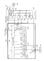
- FIG. 3 is a detailed configuration diagram of the power supply circuit and the LSI according to the embodiment.
- the power supply circuit 322-1 and power supply circuit 322-2, LSI 323-1 and LSI 323-2, DIMM 324-1 and DIMM 324-2 in FIG. 2 have the same configuration. Therefore, in FIG. 3, only the power supply circuit 322-1, the LSI 323-1, and the DIMM 324-1 are described, and the description of the power supply circuit 322-2, the LSI 323-2, and the DIMM 324-2 is omitted.
- the BMC 321 When the BMC 321 turns on the switch 343, power is supplied from the power supply 344 provided in the server 301-1 to the power supply circuit 322-1.
- the BMC 321 receives a power-on instruction from the MMB 201 via the MB 321, the BMC 321 turns on the switch 343 and supplies power from the power supply 344 to the power conversion elements 341-1 to 341-4.
- the BMC 321 outputs an enable signal that is a power supply instruction to the power conversion elements 341-1 and 341-4.
- the BMC 321 outputs a reset signal (reset1) that initializes the elements in the domain 1 to the domain 1 of the LSI 321-1.
- the BMC 321 When the BMC 321 receives the PWRGOOD signal indicating the completion of preparation from the AND circuit 342, the BMC 321 outputs the PWRGOOD signal to the System Control unit 351. At this time, the BMC 321 turns off the reset signal (reset1).
- the voltage conversion elements 341-1 to 341-4 may be referred to as VR1 to VR4 or power supply 1 to power supply 4, respectively.
- the voltage conversion elements 341-1 to 341-4 correspond to any one of the domains 1 to 4 of the LSI 323-1, convert the voltage input from the power supply 344, and convert the converted voltage to the corresponding domains 1 to 4. Supply each.
- the voltage conversion element 341-4 also supplies power to the DIMM 324-1.
- Each of the voltage conversion elements 341-2 to 341-4 has a register (not shown) therein, and holds the current output voltage value in the register.
- the power conversion elements 341-1 and 341-4 that have received the Enable signal indicate that they are ready when power can be supplied to the LSI 313-1 at the initial voltage (for example, 1.5 V) (ie, the power supply is stabilized).
- the PWRGOOD signal is output to the AND circuit 342.
- the power conversion elements 341-1 and 341-4 are each supplied with electric power at an initial voltage.
- the initial setting voltage of the power conversion elements 341-2 and 341-3 is 0 V, that is, no power is supplied from the power conversion elements 341-2 and 341-3 to the LSI 313-1.
- the AND circuit 342 outputs a logical product of the PWRGOOD signals from the voltage conversion element 341-1 and the voltage conversion element 341-4 to the BMC 321. That is, when the PWRGOOD signal is output from the voltage conversion element 341-1 and the voltage conversion element 341-4, the PWRGOOD signal is output from the AND circuit 342 to the BMC 321.
- the LSI 323-1 is equipped with a sequencer described below, and these are called self-supporting circuits.
- the LSI 323-1 is divided into domains as regions to which power is supplied from each voltage conversion element 341. Regions to which electric power is supplied from voltage conversion elements 341-1 to 341-4 are referred to as domains 1 to 4, respectively.
- IO unit 353 belong to domain 1
- PLL Control unit 354 Register SetUp unit 355, Power Reorder unit 356, Clock Gated unit 357, Power Up unit 358 belong to domain 2.
- IO Macro part 359 belongs to domain 4.
- the System control unit 351 performs operation order management, operation instruction, monitoring, and the like of the power control units 352 and 358, the PLL control unit 354, the register control unit 355, the power control unit 355, and the clock control unit 357.
- Terminals (Strap) 360-1 and 360-2 are connected to the System Control unit 351.
- Strap 360-1 and 360-2 may be represented as Strap A and Strap B, respectively.
- a signal indicating whether or not the power-on sequence processing is to be performed from the outside is input to Strap 360-1.
- a signal indicating whether to stop the power-on sequence process temporarily or to start the temporarily stopped process is input to Strap 360-2.
- the straps 360-1 and 360-2 are connected to, for example, a switch provided on the SB 320-1, a BMC 321, or the like. As a result, signals set in the switches, control signals transmitted from the MMB 210 via the BMC 321 and the like are input to the straps 360-1 and 360-2.
- the System Control unit 351 outputs a Ready response or an interrupt response to the BMC 321.
- the Power Up unit 352 issues a voltage adjustment instruction to the voltage conversion elements 341-2 to 341-4 and generates a reset signal. Further, the Power Up unit 352 may be expressed as Power Up1.
- the IO unit 353 is an interface between the power up unit 352 and the voltage conversion elements 341-2 to 341-4.
- the PLL control unit 354 controls oscillation of each PLL (not shown) in the LSI 323-1.
- the Register SetUp unit 355 reads a signal from the Strap 360-3 connected to the Register SetUp unit 355 and instructs simultaneous setting to the setting register.
- Strap360-3 may be represented as Strap C.
- the Power Reorder unit 356 acquires information of the DIMM 324-1 and changes the power supply voltage when the DIMM 324-1 can operate at a voltage lower than the initial voltage, for example.
- the Power Reorder unit 356 and the DIMM 324-1 are connected by a serial interface.
- the Clock Gated unit 357 starts supplying the clock from the PLL to the elements in the LSI 323-1 and puts the elements in the LSI 323-1 into an operable state.
- the Power Up unit 358 issues a voltage adjustment instruction and a reset signal to the voltage conversion elements 341-3 to 341-4 via the Power Up unit 352.
- the Power Up unit 358 may be expressed as Power Up2.
- the Memory IO Macro unit 359 is an interface that transmits / receives data to / from the DIMM 324-1.
- 4A and 4B are diagrams illustrating a power-on sequence of the LSI according to the embodiment.
- step S601 the System / Control unit 351 determines whether a PWRGOOD signal is input from the BMC 321. If it is determined that the PWRGOOD signal has been input, control proceeds to step S602.
- step S602 the System Control unit 351 determines whether or not the signal of StrapSA is on (that is, whether or not the power-on sequence processing is performed from outside).
- the signal of Strap A is on
- the power-on sequence is executed by external control, so the processing is stopped.
- the control proceeds to steps S603 and S605, and the LSI 323-1 Continue the power-on sequence by the internal sequencer.
- the LSI 323-1 of the embodiment can suppress the operation of the power-on sequence by the sequencer in the LSI 32-1 by the signal of the external terminal (Strap).
- a function is called a self-supporting circuit inhibition function, and is used, for example, when controlling a power-on sequence from the outside.
- step S603 the System Control unit 351 starts a timer and determines whether the timer has expired. The timer expires after a predetermined time. When the timer has expired (timed out), the control proceeds to step S604, and when the timer has not expired, the operation of S603 is continued.
- step S ⁇ b> 604 the System Control unit 351 outputs an interrupt response to the BMC 321. If the power-on sequence is not completed within a predetermined time as in the processing of steps S603 to S604, an interrupt response is output to the BMC 321.
- step S605 the System Control unit 351 outputs a voltage adjustment instruction for the voltage conversion element 341-2 (VR2) to the Power Up unit 352.
- step S606 the power up unit 352 transmits a command and a parameter for adjusting to a specified voltage (target voltage) to the voltage conversion element 341-2.
- the voltage conversion element 341-2 adjusts the output voltage to the specified voltage using the received command and parameter.
- the voltage conversion element 341-2 writes the value of the output voltage in a register built in the voltage conversion element 341-2.
- step S607 the Power Up unit 352 polls the register built in the voltage conversion element 341-2 and checks the output voltage stored in the register. If the output voltage is equal to the specified voltage (that is, when the voltage adjustment is completed), control proceeds to step S608.
- step S608 the Power Up unit 352 turns off the reset signal (reset2) to each element in the domain 2 of the LSI 323-1 (that is, the region operated by the power from the voltage conversion element 341-2). Then, the Power Up unit 352 notifies the System Control unit 351 of completion of adjustment.
- step S609 when the system control unit 351 receives a notification of completion of adjustment in the power up unit 352, the control proceeds to step S610.
- step S610 the System Control unit 351 performs a suspension process by Strap B according to the situation. The temporary stop process will be described later.
- step S611 the System Control unit 351 outputs a voltage adjustment instruction for the voltage conversion element 341-3 (VR3) to the Power Up unit 358.
- step S612 the power up unit 358 transmits a command and a parameter for adjusting to a specified voltage to the voltage conversion element 341-3 via the power up unit 352.
- the voltage conversion element 341-3 adjusts the output voltage to the specified voltage using the received command and parameter.
- the voltage conversion element 341-3 writes the value of the output voltage in a register built in the voltage conversion element 341-3.
- step S613 the power up unit 358 polls the register built in the voltage conversion element 341-3 and checks the output voltage stored in the register. If the output voltage is equal to the specified voltage (that is, when the voltage adjustment is completed), control proceeds to step S614.
- step S614 the Power Up unit 358 turns off the reset signal (reset3) to each element in the domain 3 of the LSI 323-1 (that is, the region operated by the power from the voltage conversion element 341-3). Then, the Power Up unit 358 notifies the System Control unit 351 of completion of adjustment.
- step S615 when the system control unit 351 receives a notification of adjustment completion, the control proceeds to step S616.
- the System Control unit 351 performs a suspension process using Strap B depending on the situation.
- step S617 the System Control unit 351 instructs the PLL control unit 354-p to oscillate.
- step S618-p the PLL control unit 354-p sets a frequency in a PLL (not shown) connected to the PLL control unit 354-p, and executes a predetermined oscillation sequence.
- step S619-p when the PLL is stabilized, the PLL control unit 354-p notifies the system control unit 351 of the completion of oscillation.
- step S620 when the system control unit 351 receives notification of the completion of transmission from all the PLL control units 354-p, the control proceeds to step S621.
- step S621 the System Control unit 351 may perform a pause process using StapB.
- step S622 the System Control unit 351 instructs the Register SetUp unit 355 to set a register.
- step S623 the Register SetUp unit 355 acquires information from the Strap C 360-3.
- step S624 the Register SetUp unit 355 determines the operation mode (for example, high speed, medium speed, low speed, etc.) of the LSI 323-1 based on the acquired information.
- step S625 the Register SetUp unit 355 transmits a setting pulse for setting the mode in which the value of the register is determined to the register in the LSI 323-1. Then, the Register SetUp unit 355 notifies the System Control unit 351 of the completion of register setting.
- step S626 when the system control unit 351 receives a register setting completion notification, the control proceeds to step S627.
- the System Control unit 351 may perform a pause process using StapB.
- step S628 the System Control unit 351 transmits an instruction to acquire information on the DIMM 324-1 to the Power Reorder unit 356.
- step S629 the power reorder unit 356 acquires information indicating the operating voltage of the DIMM 324-1 from the DIMM 324-1.
- step S630 the Power Reorder unit 356 determines whether or not the voltage of the DIMM 324-1 needs to be readjusted based on the acquired operating voltage information. If readjustment is necessary, for example, if the operating voltage of the DIMM 324-1 is lower than the current output voltage (initial voltage) of VR4, the control proceeds to step S531, and if readjustment is not required, the Power Reorder unit 356 Notifies the System Control unit 351 of completion of DIMM adjustment.
- step S631 the Power Reorder unit 356 turns on the reset signal to the Memory IO Macro unit 359 and the DIMM 324-1.
- the Power / Reorder unit 356 instructs the Power / Up unit 358 to adjust the voltage of the voltage conversion element 341-4.
- the Power ⁇ Reorder unit 356 transmits information on the acquired operating voltage to the Power Up unit 358.
- step S632 the Power Up unit 358 transmits a command and parameters for adjusting the operating voltage of the DIMM 324-1 to the voltage conversion element 341-4 via the Power Up unit 352.
- the voltage conversion element 341-4 adjusts the output voltage to the operating voltage using the received command and parameter.
- the voltage conversion element 341-4 writes the value of the output voltage in a register built in the voltage conversion element 341-4.
- step S633 the Power Up unit 358 polls the register built in the voltage conversion element 341-4 and checks the output voltage stored in the register. If the output voltage is equal to the operating voltage (that is, when the voltage adjustment is completed), control proceeds to step S634.
- step S634 the Power Up unit 358 turns off the reset signal to the DIMM 324-1. Then, the Power Up unit 358 notifies the System Control unit 351 of the completion of DIMM adjustment.
- step S635 when the System Control unit 351 receives the DIMM adjustment completion, the control proceeds to step S636.
- step S636 the System Control unit 351 may perform a pause process using StapB.
- step S637 the System Control unit 351 instructs the Clock Gated unit 357 to supply a clock.
- step S638 the Clock Gated unit 357 determines the operation mode of the LSI 323-1 based on the information acquired in step S623.
- step S639 the Clock Gated unit 357 starts supplying the clock from the PLL to each element in the LSI 323-1 corresponding to the determined operation mode. That is, the supply of clocks to unused circuits and high-speed interfaces is suppressed according to the operation mode.
- step S640 the clock gated unit 357 waits for the clock to propagate to each element, and notifies the system control unit 351 of the completion of clock supply after a predetermined time has elapsed.
- step S641 when the system control unit 351 receives a clock supply completion notification, the control proceeds to step S642.
- step S642 the System Control unit 351 outputs a Ready response indicating completion of preparation to the BMC 321. Further, the System Control unit 351 stops the process of step S603, that is, stops the timer so that no interrupt response is output.
- FIG. 5 is a detailed flowchart of the suspension process. The process shown in FIG. 5 corresponds to the processes of steps S610, S616, S621, S627, and S636 of FIGS. 4A and 4B.
- step S651 the System Control unit 351 determines whether the signal from the Strap B 360-2 is on or off. If the signal of Strap B360-2 is on, control proceeds to step S652, and if it is off, no pause processing is performed.
- step S652 the System Control unit 351 determines whether or not there is an activation instruction from the Strap B 360-2, and if there is an activation instruction, ends the suspension process. On the other hand, if there is no activation instruction, control returns to step S652, that is, the System Control unit 351 waits until there is an activation instruction from Strap B.
- each sequence can be synchronized between servers.
- the temporary stop process it can be stopped once by the completion notification of each sequence, so that the state at the time of occurrence of the problem can be confirmed and investigated.
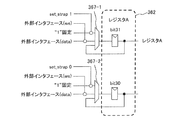
- FIG. 6 is a diagram illustrating a configuration relating to register setting of the LSI according to the embodiment. Here, a case where values are set in the control register 361 and the register 362 in the LSI 323-1 will be described.
- the LSI 323-1 can set the values of the control register 361 and the register 362 from both outside (MMB 210) and inside (RegisterRegSetUp unit 355) by the following configuration and operation.
- the LSI 323-1 further includes a control register 361, a register 362, an interface generation unit 363, an interface control unit 364, an arbiter 365, a register simultaneous setting unit 366, and a selector.
- the MMB 210 When setting values in the control register 361 and the register 362 from the MMB 210, the MMB 210 outputs a control signal to the Interface Control unit 364 via the MB 310 and the BMC 321.
- the Interface control unit 364 generates an address data signal, a write data signal, and a timing data (write enable (WE)) signal used for writing to the control register 361 based on a control signal from the MMB 210 and outputs the address data signal to the arbiter 365.
- WE write enable
- the control register 361 is a register that needs to be set according to a predetermined setting procedure.
- the register 362 is a register that does not need to be set according to a predetermined setting procedure. Writing to the control register 361 is performed as follows.
- the Register SetUp unit 355 generates a write command and outputs it to the Interface generation unit 363.
- the interface generation unit 363 generates an address data signal, a write data signal, and a timing data (write enable (WE)) signal from the write command and outputs them to the arbiter 365.
- the signal generated by the Interface generation unit 363 is a signal having the same format as the signal generated by the Interface / Control unit 364.
- the arbiter 365 uses the path from the Interface ⁇ ⁇ Control unit 364 to access the control register 361 as the path 1 and the path from the Interface generation unit 363 to the control register 361 as the path 2, performs arbitration for the two paths, and sends the path to the control register 361. Access. Which path the arbiter 365 selects is determined by the arbiter 365 referring to a register storing information indicating whether the control register 361 is set from the outside or the control register 361 is set from the inside. Select a path.
- the LSI 323-1 can set the control register 361 from both outside (MMB 210) and inside (RegisterRegSetUp unit 355) of the LSI 323-1.
- the Register SetUp unit 355 reads the Strap 360-3, determines the mode based on the information from the Strap 360-3, and outputs a strap signal (set_strap *) corresponding to the determined mode to the register simultaneous setting unit 366.
- the register simultaneous setting unit 366 outputs a strap signal to the selector 367.
- the strap signal set_strap * is transmitted simultaneously to the plurality of selectors connected to each register.
- the Interface Control unit 364 outputs an address data signal, a write data signal, and timing data to the selector 367.
- the selector 367 selects either the signal from the Interface Control unit 364 or the signal from the register simultaneous setting unit 366 and outputs the selected signal to the register 362.
- the register 362 is set to the value of the signal input from the selector 367.
- a plurality of registers can be set at the same time by transmitting signals to those registers, specifically, selectors connected to the registers.
- FIGS. 7A and 7B are diagrams illustrating register writing according to the embodiment.
- register 362 is assumed to be register A, and writing to bit 30 and bit 31 of register A will be described.
- the selector 367-1 connected to bit 31 of the register A has a logical product of a signal whose value is fixed to “1” and the strap signal set_strap1 from the Register SetUp unit 355, and an interface from the Interface Control unit 364 (external interface).
- a logical product of the write data signal (data) and the timing data (we) is input.
- the selector 367-2 connected to bit 30 of the register A has a logical product of a signal whose value is fixed to “1” and the strap signal set_strap 0 from the Register SetUp unit 355, and an interface Control unit 364 that is an external interface.
- a logical product of the write data signal (data) and the timing data (we) is input.
- bits 30 and bi31 of the register A are set as follows according to the strap signal.
- register 362 is assumed to be register B, and writing to bit 30 and bit 31 of register B will be described.
- the selector 367-1 connected to the bit 31 of the register B has a logical product of a signal whose value is fixed to “1” and the strap signal set_strap0, a write data signal (data) from the Interface Control unit 364, and timing data ( logical product with we) is entered.
- the selector 367-2 connected to bit 30 of the register B has the logical product of the signal whose value is fixed to “1” and the strap signal set_strap 0 or set_strap 1, the write data signal (data) from the Interface Control unit 364 and the timing. Logical AND with data (we) is input.
- bits 30 and bi31 of the register B are set as follows according to the strap signal.
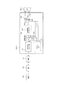
- FIG. 8 is a diagram illustrating a configuration related to adjustment of the power supply circuit of the LSI according to the embodiment.
- the power supply circuit 322 is connected to the LSI 323 through a dedicated interface, and the power supply circuit 322 and the BMC 321 are not directly connected.
- the power supply circuit 322 can be adjusted from the outside via the LSI as described below.
- the power supply circuit 322 is adjusted using the configuration described below.
- the LSI 323-1 further includes an Interface control unit 371, a power control register 372, a Status register 373, a power adjustment sequencer 374, an OR circuit 375, an AND circuit 376, and a selector 377.
- the MMB 210 writes a voltage adjustment command (including a voltage parameter) to the power supply control register 372 inside the LSI 323-1 via the MB 310, the BMC 321, and the Interface control unit 371 using an external interface.
- the Interface / Control unit 371 reads / writes data from / to the power control register 372 and the Status register 373.
- the power adjustment sequencer 374 When a voltage adjustment command for adjusting the target voltage is written in the power control register 372 inside the LSI 323-1 by the MMB 210, the power adjustment sequencer 374 operates. The power supply adjustment sequencer 374 transmits a voltage adjustment command to the power supply circuit 322-1 to be voltage adjusted.
- the power supply adjustment sequencer 374 transmits a voltage adjustment command to the selector 377.
- the selector 377 selects either the voltage adjustment command from the power supply adjustment sequencer 374 or the voltage adjustment command from the Power / Up unit 352 and outputs it to the power supply circuit 322-1.
- the selector 377 selects and outputs the voltage adjustment command from the power supply adjustment sequencer 374 when the voltage adjustment command is written in the power supply control register 372 (that is, when the power supply circuit 322-1 is controlled from the outside). To do.
- the power supply adjustment sequencer 374 transmits a clock supply start instruction to the OR circuit 375.
- the OR circuit 375 transmits a clock supply start instruction to the AND circuit 376 when a clock supply start instruction is input from either the power supply adjustment sequencer 374 or the Power Up unit 352.
- the AND circuit 376 outputs a clock to the power supply circuit 322-1 when a clock supply start instruction is input.
- the power supply circuit 322-1 When the power supply circuit 322-1 receives the voltage adjustment command from the LSI 323-1, the power supply circuit 322-1 adjusts the voltage.
- the MMB 210 uses an external interface to monitor whether or not the adjustment of the power supply circuit 322-1 is completed.
- the MMB 210 stores the Status of the power supply circuit 322-1 in the power supply control register 372 inside the LSI 323-1 via the Interface Control unit 371. Write a command.
- the power supply adjustment sequencer 374 When the Status command is written in the power supply control register 372 inside the LSI 323-1, the power supply adjustment sequencer 374 operates and transmits the Status command to the power supply circuit 322-1 that is the voltage adjustment target.
- the power supply circuit 322-1 When the power supply circuit 322-1 receives the Status command, it responds with the Status inside the power supply circuit 322-1.
- Status is, for example, the value of the output voltage of the power supply circuit 322-1.
- the LSI 323-1 stores the Status received from the power supply circuit in the Status register 373.
- the MMB 210 can know the completion of the adjustment to the target voltage of the power supply circuit 322-1 by acquiring and checking the Status stored in the Status register 373. That is, the completion of adjustment can be known by confirming whether or not the value of the output voltage of the power supply circuit 322-1 stored in the Status register 373 is equal to the target voltage.
- FIG. 9 is a flowchart of processing of the power supply adjustment sequencer according to the embodiment.
- the power supply adjustment sequencer 374 is initially in an idle state (step S611), and when a voltage adjustment command for adjusting the target voltage is written in the power supply control register 372, a clock supply start instruction is transmitted to the OR circuit 375 (step S662). .
- the power adjustment sequencer 374 transmits the contents of the power control register 372 to the selector 377 by n bits (S664). After transmitting the contents of the power supply control register 372, the power supply adjustment sequencer 374 stops transmission of a clock supply start instruction when a predetermined response period has elapsed (step S665). Then, control returns to step S661.
- a plurality of servers execute a power-on sequence such as voltage adjustment and register setting in parallel, so that the power-on sequence time of the system can be shortened. That is, since it is not necessary for the system management apparatus to execute the power-on sequence of each server one by one, even if the number of servers increases, the system power-on sequence time hardly changes.
- the register setting contents and procedure of LSI may differ depending on the version number.
- LSIs with different functions have different register types, settings, and procedures.
- LSIs may have different power supply voltages. Therefore, in the conventional system, the MMB needs to identify the type and the version number of the LSI as the LSI is transferred, and it is necessary to deal with the MMB software patch or revision. As a result, the conventional system has a problem that it takes labor and time to change LSIs.
- the power supply voltage varies depending on the type of Dual Inline Memory Module (DIMM). Therefore, in the conventional system, the MMB needs to identify the type of the DIMM along with the transfer of the DIMM, and it is necessary to deal with the patch or revision of the MMB software. As a result, the conventional system has a problem that it takes labor and time to change DIMMs.
- DIMM Dual Inline Memory Module
- the number of servers, SBs, LSIs, etc. is not limited to the case described above, and can be any number.
- FIG. 10 is a configuration diagram of a system according to another embodiment.
- a power-on sequence using a plurality of system management devices in an ultra-large scale system having a large number of servers will be described.
- the server 901-qr is connected to the system management apparatus 801-q via a serial interface.
- System management devices 801-q are connected via a network (for example, Local Area Network).
- the system management apparatus 801-1 is also called a master.
- the system management apparatus 801-q includes an MMB 810-q.
- the configuration of the MMB 810-q is the same as that of the MMB 210 in the above-described embodiment except that it is connected to another MMB.
- the devices in the system 701 are grouped, and the system management device 801-q and the server 901-qr belong to the group q.
- the server 901 has the same configuration as that of the server 301 in the above-described embodiment, and executes a power-on sequence similar to that in the above-described embodiment when receiving a power-on instruction.
- FIG. 11 is a diagram illustrating a power-on sequence of a system according to another embodiment.
- the MMB 810-1 outputs a power-on instruction to the server 901-1-r and the system management apparatuses 801-2 to 801-4.
- the server 901-1-r executes the processing of steps S 601 to S 610 and waits for an activation instruction in step S 652. In addition, the server 901-1-r notifies the MMB 810-1 of the completion of processing.
- step S1002-s when the MMB 810-s receives the power-on instruction, the control proceeds to step S1003-s.
- step S1003-s the MMB 810-s transmits a power-on (startup) instruction to the server 901-sr.
- the server 901-sr performs the processing of steps S601 to S610, and waits for an activation instruction in step S652. In addition, the server 901-sr notifies the MMB 810-s of the completion of processing.
- step S1004 when the MMB 810-1 receives processing completion from the server 901-1-r and the MMB 810-1, the control proceeds to step S1005.
- step S1005 the MMB 810-1 outputs a power-on instruction to the server 901-1-r and the system management apparatuses 801-2 to 801-4.
- the server 901-1-r executes the processes of steps S 611 to S 636 and waits for an activation instruction in step S 652.
- the server 901-1-r notifies the MMB 810-1 of the completion of processing.
- step S1006-s when the MMB 810-s receives the power-on instruction, the control proceeds to step S1007-s.
- step S1007-s the MMB 810-s transmits a power-on instruction to the server 901-sr.
- the server 901-sr performs the processing of steps S611 to S636, and waits for an activation instruction in step S652. In addition, the server 901-sr notifies the MMB 810-s of the completion of processing.
- step S1008 when the MMB 810-1 receives processing completion from the server 901-1-r and the MMB 810-1, the control proceeds to step S1005.
- step S1009 the MMB 810-1 outputs a power-on instruction to the server 901-1-r and the system management apparatuses 801-2 to 801-4.
- the server 901-1-r executes steps S637 to S642.
- the MMB 810-1 starts operation of the server 901-1-r.
- step S1010-s when the MMB 810-s receives the power-on instruction, the control proceeds to step S1011-s.
- step S1011-s the MMB 810-s transmits a power-on instruction to the server 901-sr.
- the server 901-sr executes the processes of steps S637 to S642.
- the MMB 810-2 starts the operation of the server 901-2-r.
- the system management device 801 is connected to the network, and the power-on sequence for each group is synchronized by using the suspension process, so that the power-on sequence varies between groups. Can be reduced.
Landscapes
- Engineering & Computer Science (AREA)
- Theoretical Computer Science (AREA)
- Software Systems (AREA)
- Physics & Mathematics (AREA)
- General Engineering & Computer Science (AREA)
- General Physics & Mathematics (AREA)
- Computer Security & Cryptography (AREA)
- Power Sources (AREA)
Abstract
L'invention concerne un système de traitement d'informations comprenant : une pluralité d'appareils de traitement d'informations dont chacun comporte une carte système sur laquelle sont montés un circuit intégré et un circuit d'alimentation électrique destiné à alimenter en courant le circuit intégré ; et un appareil de gestion du système qui transmet une instruction de mise sous tension à chacun des appareils de traitement d'informations. Le circuit intégré de chacun des appareils de traitement d'informations effectue un traitement de démarrage lorsque le circuit intégré reçoit l'instruction de mise sous tension.
Priority Applications (3)
| Application Number | Priority Date | Filing Date | Title |
|---|---|---|---|
| PCT/JP2011/058363 WO2012132020A1 (fr) | 2011-03-31 | 2011-03-31 | Système de traitement d'informations, appareil de traitement d'informations et circuit intégré |
| JP2013507022A JPWO2012132020A1 (ja) | 2011-03-31 | 2011-03-31 | 情報処理システム、システム管理装置、集積回路 |
| US14/035,480 US20140025966A1 (en) | 2011-03-31 | 2013-09-24 | Information processing system, system management apparatus, and integrated circuit |
Applications Claiming Priority (1)
| Application Number | Priority Date | Filing Date | Title |
|---|---|---|---|
| PCT/JP2011/058363 WO2012132020A1 (fr) | 2011-03-31 | 2011-03-31 | Système de traitement d'informations, appareil de traitement d'informations et circuit intégré |
Related Child Applications (1)
| Application Number | Title | Priority Date | Filing Date |
|---|---|---|---|
| US14/035,480 Continuation US20140025966A1 (en) | 2011-03-31 | 2013-09-24 | Information processing system, system management apparatus, and integrated circuit |
Publications (1)
| Publication Number | Publication Date |
|---|---|
| WO2012132020A1 true WO2012132020A1 (fr) | 2012-10-04 |
Family
ID=46929838
Family Applications (1)
| Application Number | Title | Priority Date | Filing Date |
|---|---|---|---|
| PCT/JP2011/058363 Ceased WO2012132020A1 (fr) | 2011-03-31 | 2011-03-31 | Système de traitement d'informations, appareil de traitement d'informations et circuit intégré |
Country Status (3)
| Country | Link |
|---|---|
| US (1) | US20140025966A1 (fr) |
| JP (1) | JPWO2012132020A1 (fr) |
| WO (1) | WO2012132020A1 (fr) |
Families Citing this family (3)
| Publication number | Priority date | Publication date | Assignee | Title |
|---|---|---|---|---|
| CN102799504A (zh) * | 2011-05-23 | 2012-11-28 | 鸿富锦精密工业(深圳)有限公司 | 电源测试系统及方法 |
| JP5936415B2 (ja) * | 2012-03-29 | 2016-06-22 | キヤノン株式会社 | 半導体集積回路、情報処理装置および制御方法 |
| US9612636B2 (en) * | 2014-09-25 | 2017-04-04 | Qualcomm Incorporated | Token-based power-switch control circuits |
Citations (4)
| Publication number | Priority date | Publication date | Assignee | Title |
|---|---|---|---|---|
| JPH1153120A (ja) * | 1997-08-08 | 1999-02-26 | Fujitsu Ltd | ディスク制御装置およびディスク制御プログラムを記録した媒体 |
| JP2006107127A (ja) * | 2004-10-05 | 2006-04-20 | Nec Electronics Corp | 半導体集積回路装置 |
| JP2007156587A (ja) * | 2005-12-01 | 2007-06-21 | Hitachi Ltd | 電源制御方法およびこれを実現するシステム |
| JP2010267096A (ja) * | 2009-05-15 | 2010-11-25 | Sharp Corp | 情報処理装置 |
Family Cites Families (6)
| Publication number | Priority date | Publication date | Assignee | Title |
|---|---|---|---|---|
| US6802014B1 (en) * | 2000-10-26 | 2004-10-05 | Apple Computer, Inc. | Method and apparatus for managing power in computer systems |
| JP2005223828A (ja) * | 2004-02-09 | 2005-08-18 | Nec Access Technica Ltd | 通信システムおよび通信復旧方法 |
| JP5077225B2 (ja) * | 2006-02-27 | 2012-11-21 | 富士通株式会社 | 情報処理装置及び処理実行方法 |
| US8397090B2 (en) * | 2006-12-08 | 2013-03-12 | Intel Corporation | Operating integrated circuit logic blocks at independent voltages with single voltage supply |
| JP4800289B2 (ja) * | 2007-11-30 | 2011-10-26 | 富士通セミコンダクター株式会社 | 電源制御装置及びその電源制御装置を有するシステムlsi |
| US20090204837A1 (en) * | 2008-02-11 | 2009-08-13 | Udaykumar Raval | Power control system and method |
-
2011
- 2011-03-31 WO PCT/JP2011/058363 patent/WO2012132020A1/fr not_active Ceased
- 2011-03-31 JP JP2013507022A patent/JPWO2012132020A1/ja active Pending
-
2013
- 2013-09-24 US US14/035,480 patent/US20140025966A1/en not_active Abandoned
Patent Citations (4)
| Publication number | Priority date | Publication date | Assignee | Title |
|---|---|---|---|---|
| JPH1153120A (ja) * | 1997-08-08 | 1999-02-26 | Fujitsu Ltd | ディスク制御装置およびディスク制御プログラムを記録した媒体 |
| JP2006107127A (ja) * | 2004-10-05 | 2006-04-20 | Nec Electronics Corp | 半導体集積回路装置 |
| JP2007156587A (ja) * | 2005-12-01 | 2007-06-21 | Hitachi Ltd | 電源制御方法およびこれを実現するシステム |
| JP2010267096A (ja) * | 2009-05-15 | 2010-11-25 | Sharp Corp | 情報処理装置 |
Also Published As
| Publication number | Publication date |
|---|---|
| US20140025966A1 (en) | 2014-01-23 |
| JPWO2012132020A1 (ja) | 2014-07-24 |
Similar Documents
| Publication | Publication Date | Title |
|---|---|---|
| US10853304B2 (en) | System on chip including clock management unit and method of operating the system on chip | |
| US11789515B2 (en) | Semiconductor device | |
| EP3523727A1 (fr) | Processeurs matériels à puces multiples et procédés associés | |
| US20090049325A1 (en) | Data processor | |
| EP1472610B1 (fr) | Interface de bus configurable synchrone ou asynchrone | |
| TWI747904B (zh) | 系統晶片、時鐘閘控元件、時鐘多工器元件及分頻元件 | |
| US8621159B2 (en) | Shared access memory scheme | |
| TW201306553A (zh) | 成像裝置以及控制該成像裝置的方法 | |
| US20160070582A1 (en) | Frequency and power management | |
| JP2004199664A (ja) | 同期バスを介してサブシステムを選択的に相互接続するための動的に変化可能なクロック・ドメインを有する方法および装置 | |
| WO2012132020A1 (fr) | Système de traitement d'informations, appareil de traitement d'informations et circuit intégré | |
| JP7506272B2 (ja) | メモリコントローラ電力状態 | |
| US20200183874A1 (en) | Chip to chip interface with scalable bandwidth | |
| US11157206B2 (en) | Multi-die system capable of sharing non-volatile memory | |
| TW201710823A (zh) | 時脈管理電路系統、系統單晶片以及時脈管理方法 | |
| JP2015018408A (ja) | 入出力制御回路及び入出力制御回路における同期制御方法 | |
| US11934251B2 (en) | Data fabric clock switching | |
| US10460772B2 (en) | Semiconductor device | |
| US20260093398A1 (en) | Interface control device and operating method thereof, and memory device and data processing system having the same | |
| US12327039B2 (en) | Method for controlling clock of controller and storage system | |
| US11734151B2 (en) | Precise shadowing and adjustment of on-die timers in low power states | |
| US9170768B2 (en) | Managing fast to slow links in a bus fabric | |
| CN119292448A (zh) | 时钟控制方法、装置及系统 | |
| JP2019091175A (ja) | 情報処理装置、情報処理装置の制御方法、及びプログラム | |
| JP2003316470A (ja) | 電子機器および回路基板 |
Legal Events
| Date | Code | Title | Description |
|---|---|---|---|
| 121 | Ep: the epo has been informed by wipo that ep was designated in this application |
Ref document number: 11862247 Country of ref document: EP Kind code of ref document: A1 |
|
| ENP | Entry into the national phase |
Ref document number: 2013507022 Country of ref document: JP Kind code of ref document: A |
|
| NENP | Non-entry into the national phase |
Ref country code: DE |
|
| 122 | Ep: pct application non-entry in european phase |
Ref document number: 11862247 Country of ref document: EP Kind code of ref document: A1 |