WO2012132408A1 - アレイ管理装置、アレイ管理方法、コンピュータプログラム、集積回路 - Google Patents
アレイ管理装置、アレイ管理方法、コンピュータプログラム、集積回路 Download PDFInfo
- Publication number
- WO2012132408A1 WO2012132408A1 PCT/JP2012/002116 JP2012002116W WO2012132408A1 WO 2012132408 A1 WO2012132408 A1 WO 2012132408A1 JP 2012002116 W JP2012002116 W JP 2012002116W WO 2012132408 A1 WO2012132408 A1 WO 2012132408A1
- Authority
- WO
- WIPO (PCT)
- Prior art keywords
- array
- storage
- time
- date
- storages
- Prior art date
- Legal status (The legal status is an assumption and is not a legal conclusion. Google has not performed a legal analysis and makes no representation as to the accuracy of the status listed.)
- Ceased
Links
Images


















Classifications
-
- G—PHYSICS
- G06—COMPUTING OR CALCULATING; COUNTING
- G06F—ELECTRIC DIGITAL DATA PROCESSING
- G06F11/00—Error detection; Error correction; Monitoring
- G06F11/07—Responding to the occurrence of a fault, e.g. fault tolerance
- G06F11/08—Error detection or correction by redundancy in data representation, e.g. by using checking codes
- G06F11/10—Adding special bits or symbols to the coded information, e.g. parity check, casting out 9's or 11's
- G06F11/1076—Parity data used in redundant arrays of independent storages, e.g. in RAID systems
- G06F11/1096—Parity calculation or recalculation after configuration or reconfiguration of the system
-
- G—PHYSICS
- G06—COMPUTING OR CALCULATING; COUNTING
- G06F—ELECTRIC DIGITAL DATA PROCESSING
- G06F2211/00—Indexing scheme relating to details of data-processing equipment not covered by groups G06F3/00 - G06F13/00
- G06F2211/10—Indexing scheme relating to G06F11/10
- G06F2211/1002—Indexing scheme relating to G06F11/1076
- G06F2211/1057—Parity-multiple bits-RAID6, i.e. RAID 6 implementations
-
- G—PHYSICS
- G06—COMPUTING OR CALCULATING; COUNTING
- G06F—ELECTRIC DIGITAL DATA PROCESSING
- G06F2211/00—Indexing scheme relating to details of data-processing equipment not covered by groups G06F3/00 - G06F13/00
- G06F2211/10—Indexing scheme relating to G06F11/10
- G06F2211/1002—Indexing scheme relating to G06F11/1076
- G06F2211/1059—Parity-single bit-RAID5, i.e. RAID 5 implementations
Definitions
- the present invention relates to an array management apparatus that manages an array constituted by a plurality of storages.
- Patent Document 1 As a conventional technique, there is an array management apparatus that manages an array formed by a plurality of storages (see Patent Document 1).
- data is held by a technique such as RAID (Redundant Arrays of Inexpensive Disks) 5 or RAID 6.
- RAID Redundant Arrays of Inexpensive Disks
- the state of the array is a state in which data held by the array is lost due to a failure of a plurality of storages at the same time in the future (data held by the array even if parity is used).
- the failure timing of a plurality of storages that may fail at the same time cannot be shifted, and there is a high possibility that data held in the array will be lost.
- the present invention solves the above-described problems of the prior art and aims to prevent the loss of data held in the array.
- the array management of the present invention is an array management apparatus for managing an array constituted by a plurality of storages, wherein at least two of the plurality of storages fail at the same time.
- the at least 2 It is an array management device comprising a failure time changing unit that changes the failure time of at least one of the storages in the storage unit.
- the failure time changing means changes the failure time of at least one of the at least two storages by changing the ratio of parity and data written to each storage.
- the failure time of the multiple storages that may fail simultaneously is determined. It is shifted and data loss can be prevented.
- FIG. 1 is a diagram illustrating the present system.
- FIG. 2 is a diagram showing the present system.
- FIG. 3 is a conceptual diagram of a storage address space.
- FIG. 4 is a diagram showing four storages and the like.
- FIG. 5 is a diagram showing a table for four storages.
- FIG. 6 is a diagram showing storage and the like.
- FIG. 7 is a diagram showing an address space and the like.
- FIG. 8 is a diagram showing the present system.
- FIG. 9 is a flowchart of the simultaneous failure avoidance process.
- FIG. 10A is a flowchart showing details of the operation in S1402.
- FIG. 10B is a diagram showing differences 1F1, 1F2, etc. between two times.
- FIG. 10C is a diagram showing differences 1F3, 1F4, etc. between two times.
- FIG. 11 is a diagram illustrating the time until failure occurs.
- FIG. 12 is a diagram illustrating a configuration of the array management unit.
- FIG. 13 is a flowchart of the operation of this system.
- FIG. 14 is a flowchart of the operation of this system.
- FIG. 15 is a diagram showing a table at each stage of processing.
- FIG. 16 is a flowchart showing details of the operation in S1102.
- FIG. 17 is a flowchart showing details of the operation in S1203.
- FIG. 18 is a diagram showing two graphs and the like.
- FIG. 19 is a flowchart showing details of the operation in S1401.
- FIG. 20 is a flowchart showing details of the operation in S1501.
- FIG. 21 is a flowchart showing details of the operation in S1503.
- FIG. 22 is a graph showing a data amount graph.
- FIG. 23 is a diagram showing three graphs and the like.
- FIG. 24 is a flowchart showing details of the operation in S1404.
- FIG. 25 is a flowchart showing details of the operation in S1901.
- FIG. 26 is a flowchart showing details of the operation in S2002.
- FIG. 27 is a flowchart showing details of the operation in S2003.
- FIG. 28 is a diagram showing a table of three columns, an upper column, a center column, and a lower column.
- FIG. 29 is a table showing the amount of data that can be stored.
- FIG. 30 is a table showing the occurrence frequency and the like.
- FIG. 31 is a diagram showing the amount of data that can be stored.
- FIG. 32 is a diagram showing processing efficiency and the like.
- FIG. 33 is a graph showing a block rewrite amount graph.
- FIG. 34 is a diagram showing the block rewrite amount and the like.
- FIG. 35A is a diagram showing a parity ratio and the like.
- FIG. 35B is a diagram showing four storages and the like.
- FIG. 35C is a diagram illustrating a table indicating the rewrite amount and the like.
- FIG. 36 is a diagram illustrating a table indicating the parity ratio and the like.
- FIG. 37 is a diagram showing three graphs and the like.
- FIG. 38 is a diagram showing four graphs and the like.
- FIG. 39 is a flowchart showing details of the operation in S2004.
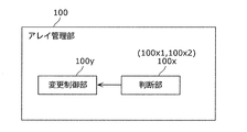
- the array management apparatus 10 is an array management apparatus 10 that manages an array 200 configured by a plurality of storages (storages 21, 22 and the like), and at least two of the plurality of storages ( ⁇ , ⁇ ) In the same period, the determination unit 100x determines whether or not the data held by the array 200 may be lost (see threshold 1F2, difference 1F1, etc.), and the array 200 holds. If it is determined that there is a possibility of data loss, a failure time changing unit 100y that changes the failure time (see date 1t) of at least one of the at least two storages (for example, ⁇ ); Is an array management device 10.
- the failure time changing unit 100y changes at least one of the at least two storages by changing the ratio of parity (refer to the area 201p) and data (refer to the area 201p) to be written to each storage.
- the failure time (for example, ⁇ ) is changed.
- the determination unit 100x includes a simultaneous failure determination unit (first portion 100x1) that determines whether at least two of the plurality of storages may fail at the same time, and the at least 2 When it is determined that one storage unit fails at the same time, it is determined whether the data held by the array 200 may be lost due to the failure of the at least two storage devices at the same time.
- An array failure determination unit (second portion 100x2) may be included.
- the loss of the data held by the array 200 hardly occurs when the date and time when the first storage fails is the first date and time, and occurs when the date and time is the second date and time.
- the first storage is a storage in which the proportion of the parity in the entire stored data and parity may be a first proportion or a second proportion,
- the date and time of the first storage is the first date and time when loss is unlikely to occur when the first rate is the first rate, and the date and time when the storage is the second rate is likely to occur.
- the determination unit 100x specifies one of the two ratios as the first ratio, specifies the other ratio as the second ratio, and changes the failure time.
- the unit 100y is the first storage The proportion of the, by the proportion of one specified, may not be in the ratio of the identified other.
- the first date and time when loss is unlikely to occur is a date and time that is more than a threshold from the date and time when the second storage fails
- the second date and time when loss is likely to occur is the second storage. It may be a date and time within a threshold from the date and time when the failure occurs.
- FIG. 1 is an implementation image diagram of the system 1.
- FIG. 2 is a configuration diagram of the system 1.
- the system 1 includes an array management device 10 and an array 200 (see FIG. 2).
- the array management device 10 controls the operation of the array 200.
- the array management apparatus 10 may be, for example, the whole or a part of a DVD (Digital Video Disc) recorder or a BD (Blu-ray Disc) recorder as shown in FIG. That is, for example, the array management apparatus 10 may be the whole or a part of a storage apparatus that includes storage (see storages 25 and 26 in FIG. 1) that records data such as moving image data received from broadcast waves.
- DVD Digital Video Disc
- BD Blu-ray Disc
- the array (storage array) 200 holds data.
- the array management apparatus 10 may transfer data held by the array 200 between the array 200 and the array management apparatus 10.
- the array management apparatus 10 may include, for example, a lower-order transfer control unit 55 (FIG. 2) that performs this transfer.
- the array management apparatus 10 may transfer the data held by the array 200 between the array management apparatus 10 and a processing unit that processes the held data.
- the array management apparatus 10 may include, for example, a higher-order transfer control unit 54 (FIG. 2) that performs this transfer.
- the processing unit described above may be a file system in an operation system that operates on a device such as a personal computer outside the array management device 10.
- data held by the array 200 may be transferred between the array 200 and an application operating on the operation system via the file system or the like and used by the application. .
- the array 200 includes a plurality of storages 201 (FIG. 2), and holds data using the plurality of storages 201.
- At least one of the plurality of storages 201 included may be, for example, a storage provided in the array management apparatus 10 as indicated by the storages 25 and 26 in FIG.
- At least one may be a storage outside the array management apparatus 10 as indicated by the storages 21 to 24 in FIG. 1, for example.
- At least one of the storages may be a storage provided in the same house as the storage provided with the array management apparatus 10, as indicated by the storages 21 to 23.
- At least one may be a storage provided in another house as indicated by the storage 24.
- the other house is a house where the parent couple lives
- the house provided with the array management device 10 may be a house where the child couple lives.
- the storage 24 in the other house is, for example, The operation may be controlled from the array management apparatus 10 via the network 1DL such as the Internet.
- FIG. 1 is merely an example. In the system 1, it may be as shown in FIG. 1 or not as shown in FIG.
- FIG. 3 is a conceptual diagram of the storage address space.
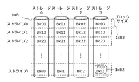
- each storage 201 (for example, storage 3 in FIG. 3) is divided into a plurality of blocks 1 ⁇ B2 (see i blocks Bk03 to Bki3, etc.).
- the array 200 includes a stripe 1xB1 (such as stripe 0 in FIG. 3) that is a storage area in which blocks (see bk00, bk01, bk02, and bk03) in each storage 201 (storages 0 to 3 in FIG. 3) are gathered. Have.
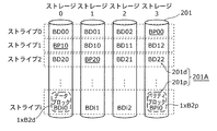
- FIG. 4 is a conceptual diagram of data / parity storage for the storage 201.
- the block 1xB2 (FIG. 3) included in the stripe 1xB1 (for example, the stripe i in FIG. 4), refer to the data block 1xB2d (see blocks BDi0, BDi1, BDi2, etc.) and the parity block 1xB2p (block BPi0, etc.) )
- the parity stored in the block 1xB2p is used when a failure occurs in another storage 201 (for example, the storage 2 in FIG. 4) other than the storage 201 having the block 1xB2p.
- the parity stored in the block 1xB2p and the data (refer to the blocks Bdi0 and Bdi1) in the respective storages (storage 0 and 1) in the stripe 1xB1 of the block 1xB2p where no failure has occurred. ) And are used.
- the number of blocks 1xB2d in which data is stored in the stripe 1xB1 is two or more, for example, three in FIG.
- the number of times the parity is written to the block 1xB2p is a relatively large number of times when the data is written to any block 1xB2d.
- the number of writes to the parity block 1xB2p (for example, BPi0) is, for example, the total number of times of writing to each of the data blocks 1xB2d (BDi0 to BDi2). That is, for example, in the example of FIG. 4, the number of data blocks 1xB2d is three, which is three times the number of times data is written to the blocks 1xB2d.
- FIG. 5 is a table showing the parity ratio 201r (seventh row) and the like in each storage 201.
- the block 1xB2 in the storage 201 includes a data block 1xB2d and a parity block 1xB2p.
- FIG. 6 is a diagram showing a data area 201d, a parity area 201p, and the like in the storage 201.
- the area 201A that is the entire storage area of the storage 201 is divided into a data area 201d and a parity area 201p.
- the data area 201d is an area in which the areas of the data blocks 1xB2d are collected (see FIG. 4).
- the parity area 201p is an area in which the areas of the respective parity blocks 1xB2p are gathered.
- the parity ratio 201r refers to the ratio of the parity area 201p to the size of the entire area 201A. That is, the parity ratio 201r is, for example, the ratio of the number of parity blocks 1xB2p to the total of the number of data blocks 1xB2d and the number of parity blocks 1xB2p included in the storage 201.
- the parity block 1xB2p is relatively small. Since the parity block has a higher access frequency than the data block, if the parity ratio is small, the storage is less likely to deteriorate compared to a storage having a high parity ratio, and the date and time 1t when the storage 201 fails (FIG. 10B). ) Is relatively late (see date and time 1t2 shown).
- the parity ratio 201r of the storage 201 is one ratio
- the failure date and time 1t of the storage 201 is different from the date and time 1t when it is the other ratio.
- FIG. 7 is a conceptual diagram of an address space in the array 200.
- the address space 200as in the array 200 is divided into portions of stripes 1xB1 (FIG. 3: stripes 0, 1, etc. in FIG. 4, for example). Then, the portion in each stripe 1xB1 (for example, stripe 1) is further divided into portions in each block 1xB2 (see blocks BD10, BD11, and BD12 in FIG. 7) in the stripe 1xB1.
- FIG. 8 is a diagram showing the system 1.
- the array management device 10 includes an array management unit 100 (FIG. 8).
- the array management unit 100 includes a parity rate management unit 101, a parity rate calculation unit 102, a parity rate change unit 103, and a failure prediction unit 104.
- the array management apparatus 10 may include a computer including, for example, a CPU 52, a RAM 53, a ROM 51, etc., as shown in FIG.
- the array management unit 100 (respective functional blocks such as the parity ratio management unit 101 provided in the array management unit 100) is executed by the computer program 101pg (FIG. 2) by this computer. It may be a functional block of a function realized in
- the computer program 101pg may be stored in the ROM 51, for example, and the stored computer program 101pg may be executed by the above computer.
- the parity ratio management unit 101 and the like are illustrated in the position of the ROM 51.
- FIG. 9 is a flowchart of simultaneous failure avoidance processing.
- the failure prediction unit 104 calculates a failure prediction date and time that is a date and time when a failure occurs in each storage 201.
- the parity ratio calculation unit 102 calculates whether or not there is a possibility of simultaneous failure.
- FIG. 10A is a flowchart of a process for determining the risk of simultaneous failure occurrence.
- S1402 of FIG. 9 for example, the processing of FIG. 10A may be performed.
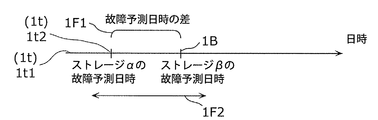
- FIG. 10B is a diagram showing the first date and time 1t1, the second date and time 1t2, and the like.
- the storage 201 for which the earliest failure prediction date (see date 1t in FIG. 10B) is calculated is identified as the first storage ⁇ (see FIG. 10B).
- the second storage ⁇ is specified.
- the second storage ⁇ is the storage 201 for which the M + 1 earliest failure prediction date (date 1B in FIG. 10B) is calculated among the specified failure prediction dates of the plurality of storages 201.
- M is the allowable number of failures in the array 200 (maximum allowable number of failures). As long as a failure only occurs in the number of storages 201 equal to or less than the number of failures, the loss of data held by the array 200 does not occur, and when a failure occurs in a number larger than that number, It is the number that disappears. That is, the allowable number of failures is, for example, one when the array 200 operates at RAID5, and two when the array 200 operates at RAID6.
- the storage 201 has the earliest failure prediction date and time.
- the failure prediction date / time (date / time 1t) of the first storage ⁇ is within the threshold 1F2 from the failure prediction date / time (date / time 1B) of the second storage ⁇ , and the failure prediction date / time (date / time 1B) of the second storage ⁇ . It is determined whether or not the same period.
- the threshold 1F2 is after the failure prediction time (date 1t) of the first storage ⁇ and the second storage ⁇ has failed.
- Threshold value of a value at which data loss occurs (it is assumed) that the failed storage 201 such as the first storage ⁇ is not replaced or repaired before the predicted failure time (date 1B) It is.
- the threshold value 1F2 is replaced with a failed storage 201 during the period of the large difference 1F1, and no data is lost ( A threshold value).
- FIG. 10C is a diagram showing the difference 1F3, the difference 1F4, and the like.
- FIG. 10C it may be as shown in FIG. 10C.
- the above-described first storage ⁇ may be, for example, the first storage ⁇ 1 written in FIG. 10C, and the second storage ⁇ may be the second storage ⁇ 2.
- the third storage ⁇ is a storage 201 whose failure prediction date and time of the third storage ⁇ is after the failure prediction date and time of the first storage ⁇ 1 and before the second storage ⁇ 2.
- the process to be performed is selected based on the determination (S1402) whether or not there is a possibility of data loss.
- the parity ratio changing unit 103 may perform the same control as the control performed on the array 200 immediately before the current time.
- the parity ratio changing unit 103 performs control different from the control for the array 200 performed immediately before the current time.
- the date and time 1t when the first storage ⁇ fails is far from the threshold value 1F2 from the date and time 1B when the second storage ⁇ fails, and data loss is not the same period.
- This is a control in which (not estimated) occurs.
- the parity ratio 201r1 in the storage 201 included in the array 200 is the parity ratio in the storage 201 when the control performed immediately before the current is performed.
- the above-described difference 1F1 is relatively large, and the time of failure is not the same period.
- FIG. 11 is an image diagram of simultaneous failure avoidance.
- the comparative example shown in FIG. 11 shows a case in another assumed technique different from the present embodiment.
- the determination as to whether or not they are at the same time (FIG. 9: S1402) is not performed, the control to be performed is not changed, and data loss occurs (S12 to S13 in FIG. 11). ).
- FIG. 12 is a diagram showing the array management apparatus 10.
- the array management apparatus 10 may include, for example, a determination unit 100x and a change control unit (failure time deflection unit) 100y.
- the determination unit 100x includes the parity ratio calculation unit 102 (FIG. 8 and the like) and the failure prediction unit 104 described above, and the change control unit 100y includes a parity ratio management unit 101, a parity ratio change unit 103, and the like. May be included.
- the operation may be performed by the determination unit 100 x using the parity ratio calculation unit 102.
- the failure prediction unit 104 and the like are also the same as this example.
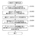
- FIG. 13 is a flowchart of the reception data writing process.
- the processing shown in FIG. 13 may be performed.
- the array management apparatus 10 receives data that is requested to be written to the array 200.
- the stripe 1xB1 (see FIG. 3) where the received data is recorded is specified.
- the parity of the data is generated by the array management apparatus 10.
- processing based on information 101I (FIG. 8) stored by the parity ratio management unit 101 is performed.
- the information 101I specifies the block 1xB2 in which the received data is recorded (one or more) and the generated block 1xB2 in which the parity of the data is recorded in the specified stripe 1xB1. Information.
- information 101I may have, for example, the data structure in the second to fifth rows in the table of FIG.
- the information 101I may be the table shown in FIG.
- the received data is specified, the data is recorded in the block 1xB2d (one or more) to be recorded, and the generated parity is specified, the block 1xB2p in which the parity is to be recorded To be recorded.
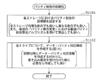
- FIG. 14 is a flowchart of the parity ratio initialization process.
- FIG. 15 is a diagram showing an example of transition of the correspondence table (see FIG. 5 described above) in the data / parity correspondence information creation work.
- the array management apparatus 10 specifies the target value of the parity ratio 201r in each storage 201 (the seventh row in each table of FIG. 15). Note that the target value of the parity ratio of each storage may be non-uniform in each storage. In S1102, the information 101I is created by the array management apparatus 10 based on the specified target values.
- FIG. 16 is a flowchart of the parity ratio initialization process. In S1102 of FIG. 14 described above, for example, the processing of FIG. 16 may be performed.
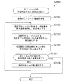
- the parity ratio 201r (seventh row) of each storage (each column) in the table of information 101I (FIG. 5) is initialized to zero.
- the first stripe (for example, stripe 0 in FIG. 5) is selected as the selected stripe.
- the value of each storage (each column) column of the row of the selected selected stripe (for example, the row of stripe 0) in the table of information 101I is specified.
- S1204 it is determined whether or not all the stripes have been processed. If it is determined in S1205 that the process has not been completed (S1204: NO), the next stripe after the selected stripe in the immediately preceding process of S1203 is selected as the selected stripe (see processes 1C1 to 1C2, etc. in FIG. 15). ). On the other hand, when it is determined that the processing of all stripes has been completed (S1204: YES), the processing of FIG. 16 ends.
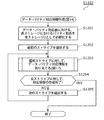
- FIG. 17 is a flowchart of data / parity correspondence information allocation processing for a stripe. In S1203 of FIG. 16, for example, the processing of FIG. 17 may be performed.
- a predetermined number of storages 201 are selected.
- the order of the value (eighth line) obtained by subtracting the current ratio (sixth line in the table of FIG. 15) from the target value (S1101) of the parity ratio 201r described above is from the largest order.
- the storages 201 in each order up to the predetermined number-th order are selected.
- the predetermined number described above is one if the array 200 operates in RAID5, and two if the array 200 operates in RAID6.
- the block 1xB2 of each storage 201 of the selected number of storages 201 in the stripe to be processed in FIG. 17 is identified as a parity block 1xB2p (FIG. 3, FIG. 3). (See FIG. 4).
- the block 1xB2 of each of the other storages 201 is specified as the data block 1xB2d (see processing 1C1, 1C2, etc. in FIG. 15).
- FIG. 18 is an image diagram of a process for calculating a predicted failure date and time.
- FIG. 19 is a flowchart of the process of calculating the failure prediction date and time. In S1401 of FIG. 9 described above, for example, the processing of FIG. 19 may be performed.
- the function f is a function of the relationship between the date and time and the cumulative amount of writing to the array 200 at that date and time.
- the first storage is selected as the selected storage.
- the function g j indicated by the right graph in the lower column of FIG. 18 for the selected selected storage is specified.
- the function g j is the selected storage at the accumulated amount of writing to the array 200 (horizontal axis in the lower graph) and the date and time when the accumulated amount was written to the array 200. This is a function for specifying the relationship between the amount of writing to the cumulative amount.
- the guaranteed amount in the selected storage is specified.
- the guaranteed amount is an amount that is guaranteed by the manufacturer of the selected storage so that no failure occurs in the selected storage until the data amount of that amount is written. That is, the guaranteed amount is an amount that is estimated to cause a failure at the date and time when the data amount of this amount is written (close date and time).
- the date and time when the cumulative amount of writing to the array 200 becomes the specified cumulative amount is specified as the failure prediction date and time of the selected storage.
- S1507 it is determined whether or not the failure prediction date / time of all storages has been specified in S1506 described above. If it is determined that it has been performed (S1507: YES), the processing in FIG. 19 ends. On the other hand, if it is determined in S1508 that the processing for all the storages has not been completed (S1507: YES), the storage 201 next to the selected storage in the processing in the immediately preceding S1503 to S1507 is the next S1504 to S1504. It is specified as the selected storage in the processing in S1507.
- FIG. 20 is a flowchart of the process of calculating the degree of increase in the cumulative write data amount.
- S1501 of FIG. 19 described above for example, the processing of FIG. 20 may be performed.
- the current date and time are acquired.
- the current date and time may be acquired from a clock provided in the array management apparatus 10 that measures the current date and time.
- the current cumulative amount of writing to the array 200 is acquired. Note that, for example, this accumulated amount is stored by a predetermined storage unit provided outside the array management apparatus 10 such as the array 200, and the stored accumulated amount is acquired by the array management apparatus 10. Good.
- the acquired current date and current accumulated amount of writing to the array 200 are stored in the storage area of the array management apparatus 10 in association with each other.
- the respective circles in the left graph of the two graphs in the lower column of FIG. 18 are the date and time stored in association with each other in the storage area of the array management device 10 and the writing to the array 200 at that date and time. Indicates the cumulative amount of.
- FIG. 21 is a flowchart of the process of calculating the degree of increase in the cumulative rewrite amount for the storage. In S1503 of FIG. 19 described above, the processing of FIG. 21 may be performed.
- the current cumulative amount of writing to the array 200 is acquired.
- the current cumulative amount of writing to the selected storage (previously described) is acquired. Note that, for example, the cumulative amount acquired in S1702 is stored in a predetermined storage unit provided in the selected storage, and the cumulative amount stored in the storage unit is acquired to the array management apparatus 10. Good.
- the cumulative amount acquired in S1701 and the cumulative amount acquired in S1702 are stored in the storage area of the array management apparatus 10, respectively.
- the function g j of the selected storage (see the graph on the right in FIG. 18) is specified.
- a regression analysis technique or the like may be used as in the specific process of the function f in S1604.
- FIG. 22 is a graph showing data of three failure prediction functions.
- the failure prediction function of the storage j is “function f ⁇ function g j ” (combination function of the function f and the function g j ).
- the failure prediction functions in the different storages 201 are usually different functions. Further, as shown in the figure, for example, the guaranteed amounts (previously described) of the different storages 201 may be different from each other.
- FIG. 23 is an image diagram of the simultaneous failure occurrence.
- FIG. 23 shows an upper column indicating the first case in which a simultaneous failure occurs, an interruption column indicating the second case, and a lower column indicating the third case.
- FIG. 24 is a flowchart of the simultaneous failure avoidance process. In S1404 of FIG. 9, for example, the processing of FIG. 24 may be performed.
- information 101I is created.
- the information 101I to be created is information in which the parity ratio in each storage 201 in the table of FIG. 5 is the appropriate (optimal) parity ratio 201r in the storage 201 calculated. .
- swap processing is appropriately performed for each stripe.
- whether the block 1xB2 is a data block 1xB2d or a parity block 1xB2p is in accordance with the created information 101I (see FIG. 5)
- the data structure of each storage 201 is changed to the data structure of the created information 101I.
- the created information 101I is overwritten on the information 101I (see FIG. 8) stored by the parity ratio management unit 101 before the processing of FIG. 24 is performed.
- the new information 101I created by the parity ratio management unit 101 is stored.
- FIG. 25 is a flowchart of the optimal parity ratio calculation process. In S1901 of FIG. 24, for example, the processing of FIG. 25 may be performed.
- FIG. 26 is a flowchart of processing for calculating the allowable remaining rewrite amount of each storage. In S2002 of FIG. 25, for example, the processing of FIG. 26 may be performed.
- the first storage is selected as the selected storage.
- the guaranteed amount of the selected storage is acquired.
- the current cumulative amount of writing to the selected storage is acquired.
- an amount obtained by subtracting the current accumulated amount from the acquired guaranteed amount is specified as the allowable remaining rewrite amount.
- S2105 it is determined whether or not the processing of all the storages 201 has been completed. If it is determined that the process has been completed (S2105: YES), the process of FIG. 26 is completed. On the other hand, if it is determined in S2106 that the processing has not ended (S2106: NO), the next storage 201 is selected as the selected storage.
- the specified function is a function that specifies the relationship between the parity ratio 201r in the storage 201 and the write amount to the storage 201 at the parity ratio 201r (see FIG. 33).
- FIG. 27 is a flowchart of the processing of the storage parity ratio and the block rewrite amount. In S2003 in FIG. 25, for example, the processing in FIG. 27 may be performed.
- FIG. 28 is an explanatory diagram of simultaneous data block rewriting.
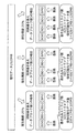
- the first pattern at the time of writing to the array 200 is shown in the upper column
- the second pattern is shown in the middle column
- the third pattern is shown in the lower column.
- parity is written to one storage 201 (storage 3) and data is written to one storage 201 (storage 0).
- the second pattern parity is written to one storage 201 (storage 3) and data is written to two storages 201 (storage 0, 1).
- parity is written to one storage 201 (storage 3) and data is written to three storages 201 (storages 0 to 2).
- FIG. 29 is a relationship diagram between the number of simultaneously rewritten data blocks and the amount of stored data.
- the amount of data to be written in writing to the array 200 in each pattern is, for example, as shown in FIG.
- frequency information is acquired.
- the acquired frequency information includes the first frequency (probability) at which writing of the first pattern occurs and the second frequency (probability) at which writing of the second pattern occurs as writing to the array 200;
- a third frequency (probability) at which writing of the third pattern occurs is specified.
- FIG. 30 is an example of a data block simultaneous rewrite occurrence frequency information management table.
- FIG. 30 shows a case in which 25% is specified as the first frequency, 40% is specified as the second frequency, and 35% is specified as the third frequency, based on the acquired information.
- FIG. 31 is a diagram of data allocation according to the frequency of simultaneous data block rewriting.
- writing in the first, second, and third patterns is performed at the above-described first, second, and third frequencies (25%, 40%, and 35%). Done. Then, 1 MB, 2 MB, and 3 MB are written in each pattern.
- the amount of data written in the first, second, and third patterns is 2520 MB ⁇ (25 MB / (25 MB + 80 MB + 105 MB)).
- 2520 MB x (25 MB / 210 MB) 300 MB
- 2520 MB x (80 MB / 210 MB) 960 MB
- 2520 MB x (105 MB / 210 MB) 1260 MB (see the bottom of Fig. 31).
- the number of stripes (300, 480, 420) to be written in the first, second, and third patterns is specified from the amount of data written to the array 200 (250 MB).
- the first, second, and third patterns are written when the unit data amount (see 2520 MB in FIG. 31) is written to the array 200.
- Second and third stripe numbers are identified.
- the number of times of writing to the storage 201 is as follows.
- the parity ratio 201r of the storage 201 is abbreviated as x%.
- each of the stripes is a block of data.
- writing is performed only in one of the three data blocks included in the stripe.
- FIG. 32 is an explanatory diagram of the rewrite processing occurrence rate in the data block.
- the number of stripes in the proportion of x% (300 ⁇ x%) is the block 1xB2 of the storage 201 in the stripe. Is the parity block 1xB2p.
- the number of times W2 (x) of writing to the storage 201 in the first pattern and the number of times W3 (x) of writing to the storage 201 in the third pattern are specified.
- J (x) W1 (x) + W2 (x) + W3 (x).
- FIG. 33 is a diagram illustrating a graph of a function K (x) that specifies a relationship between the parity ratio 201r (the above-described x) and the amount of data written by writing the number of times J (x). By specifying the above-mentioned J (X), this K (x) is specified.
- FIG. 34 is a diagram showing the block rewrite amount in consideration of the number of simultaneously rewritten data blocks.
- W1 (x) which is the number of times in the first pattern described above, is a function in the left graph among the three graphs in the upper left column of FIG.
- W2 (x) is a function in the center graph
- W3 (x) is a function in the right graph.
- the above-described W1 (x), W2 (x), and W3 (x) are specified.
- the above-described K (x) that is, the function of the graph in the lower column of FIG. 34 is identified.
- FIG. 35A is a diagram showing combinations of parity ratios 201r in a plurality of storages 201 (storages 0 to 3).
- FIG. 35B is a diagram showing the array 200 in the combined state of FIG. 35A.
- FIG. 35C is a diagram illustrating the amount of data to be written in each storage 201 when the combination of the parity ratios 201r is the combination of FIG. 35A.
- the ratio of the amount of data written (K (x) described above) in the storages 0 to 4 is “1: 1: 1: 3”.
- FIG. 36 is a diagram showing a combination different from the combination in FIG. 35A.
- the appropriate combination specified by the array management apparatus 10 is usually not the combination shown in FIG. 35A but the combination shown in FIG.
- FIG. 37 is a diagram showing three graphs.
- the upper graph is a graph showing the relationship between the parity ratio 201r and the amount of data to be written, and is the K (x) graph described above (see the lower column in FIG. 34).
- the middle graph is a graph (L (x)) showing the relationship between the parity ratio 201r and the amount of data written to the array 200.
- the middle graph (L (x)) is specified from the upper graph (J (x)).
- the lower graph is a graph (M (x)) showing the relationship between the parity ratio 201r and the failure prediction date and time of the storage 201.
- the lower graph (M (x)) is specified from the middle graph (L (x)).
- the failure prediction date / time is specified based on this M (X) specified from the specified J (x). That is, for example, the failure prediction date and time when each storage 201 has the respective parity ratio 201r is specified.
- FIG. 38 is a diagram showing four graphs. That is, in S2004, the four graphs in FIG. 38 are specified.
- FIG. 39 is a flowchart of the process of calculating the failure prediction date and time of each storage at each parity ratio. In S2004 of FIG. 25, for example, the processing of FIG. 39 may be performed.
- a combination in which a plurality of failure prediction dates / times specified is the most appropriate among a plurality of combinations is specified (see processing 1G in FIG. 38, FIG. 10B described above, and the like). ). That is, the most appropriate combination is specified from a plurality of combinations.
- the plurality of failure prediction dates and times specified in the most appropriate combination for example, the failure prediction date and time of the first storage ⁇ described above (date and time 1t in FIG. 10B) and the second storage ⁇
- the difference 1F1 between the failure prediction date and time 1B and the failure prediction date 1B may be the maximum.
- the above-described processing is performed based on the specified optimal combination of parity ratios. That is, for example, in S1903 to S1904, the operation of the array 200 may be controlled. In other words, in the controlled operation, the parity ratio in each storage 201 in the array 200 may be the same ratio as the parity ratio of the storage 201 in the specified optimal combination (described above, (See description of S1903 and S904).
- the symbol “N stripe ” indicates the number of stripes 1 ⁇ B1 (the number of stripes) in the array 200. That is, the stripe number i can take a value from 0 to N stripe -1.
- the symbol “N storage ” indicates the number of storages 201 (the number of storages) in the array 200. However, spare storage is not included. That is, the storage number j can take a value from 0 to N storage -1.
- the symbol “N data ” indicates the number of storages of data blocks (block 1 ⁇ B2d) in each stripe (three in FIG. 4 and the like).
- each block 1xB2 is expressed in the form of Bk ⁇ ⁇ .
- ⁇ is a stripe number and ⁇ is a storage number.
- the block corresponding to the data is expressed in the form of BD ⁇ #.
- “#” is “a storage number corresponding to a data block in each stripe”.
- the block (block 1xB2p) corresponding to the parity is expressed in the form of BP * $.
- “$” is “a storage number corresponding to a parity block in each stripe”.
- the symbol “T now ” indicates the current time.
- the symbol “D now ” indicates the current cumulative amount of data written to the array.
- the symbol “T j ” indicates the date and time when storage j is predicted to be damaged in the array.
- the symbol “D j ” indicates the cumulative amount of data written to the array at the date and time T j .
- T now can be acquired.
- a mechanism for recording the past data write amount is provided in the array management apparatus 10 in advance, and D now can be acquired by using it.
- obtaining t j and d j is stated. From these t j and d j , T j and D j can be determined.
- a is a coefficient.
- the coefficient a is determined by regression analysis using records of “past data write amount” and “date and time at that time”.
- the symbol “W jnow ” indicates the current cumulative block rewrite amount for the storage j.
- the symbol “W jmax ” indicates a guaranteed value of the block rewrite amount for the storage j.
- W jnow provides a mechanism for recording the past block rewrite amount in the array management apparatus 10 in advance, and makes it possible to acquire it.
- W jmax is determined in advance by a manufacturer-guaranteed value or an acceleration test (SMART (Self-Monitoring, Analysis and Reporting Technology) may be used). Since W jnow and W jmax can be determined, w j can also be determined.
- failure prediction function g j is linear, it is expressed by the following equation (where b j is a coefficient).
- the coefficient b j is different for each storage. This is determined by regression analysis using records of “past block rewrite amount” and “data write amount to the array at that time”.
- the unit of data amount is MB and the unit of time is h).
- 4 MB of block rewrite occurs for storage j (b j 0.4) when 10 MB of data is written to the array.
- FIGS. 10A to 10C will be described.
- the symbol “T ⁇ ” indicates the date and time when the storage is predicted to be damaged first in the array. Here, let ⁇ be the storage that is predicted to be damaged first.
- the symbol “T ⁇ ” indicates the date and time when the storage is predicted to be damaged M + 1th in the array (that is, the array is damaged). Here, it is assumed that the storage predicted to be damaged M + 1 is ⁇ .
- T ⁇ and T ⁇ can be determined by rearranging after calculating T j for all storages. Since T ⁇ and T ⁇ can be determined, ⁇ ⁇ can also be determined. If ⁇ is within a predetermined value, it is determined that there is a risk of simultaneous failure.
- FIG. 10C will be described.
- the symbol “T ⁇ ” indicates the date and time when the storage is predicted to be xth damaged in the array.
- the storage predicted to be xth damaged is ⁇ .
- x can take a value of 2 to M.
- the symbol “T ⁇ 1 ” indicates the date and time when the storage is predicted to be damaged in the x ⁇ 1th time in the array.
- the storage predicted to be damaged in the (x ⁇ 1) th is ⁇ 1.
- the symbol “T ⁇ 2 ” indicates the date and time when the storage is predicted to be damaged x + 1th in the array.
- the storage predicted to be x-2th damaged is ⁇ 2.
- the value of x can take an integer value of 2 to M. If x is determined, T ⁇ , T ⁇ 1 , T ⁇ 2 , ⁇ ⁇ 1 and ⁇ ⁇ 2 can also be determined. For any x, ⁇ ⁇ 1 and ⁇ ⁇ 2 are calculated, respectively. If ⁇ 1 or ⁇ 2 is within a predetermined value, it is determined that there is a risk of simultaneous failure.
- FIG. 28 and FIG. 30 will be described.
- v indicates the number of simultaneously rewritten data blocks. v can take values from 1 to N data .
- FIG. 29 will be described.
- the symbol “BK” indicates a block size (fixed here, but may be variable).
- the symbol “C v ” indicates the amount of data that can be stored by one stripe write in the simultaneous rewrite data block count v.
- FIG. 31 will be described.
- the symbol “R v ” indicates the number of write stripes in the simultaneous rewrite data block number v.
- Symbol “P v ” represents the frequency of simultaneous rewrites in the number v of simultaneous rewrite data blocks. ( Pv can take a value from 0 to 1. The total value in the number of all simultaneously rewritten data blocks is 1 for RAID5 and 2 for RAID6).
- this d is calculated by the following equation.
- FIG. 32 will be described. First, the symbols are explained.
- the symbol “Q v ” indicates the rewrite processing occurrence rate in the data block in the simultaneous rewrite data block number v.
- FIGS. 35A to 35C will be described.
- the symbol “w vdata ” indicates the block rewrite amount that occurs in the storage of “parity ratio 0%” when writing to R v stripes in the simultaneous rewrite data block count v.
- the symbol “w vparity ” indicates the block rewrite amount that occurs in the storage of “parity ratio 100%” when writing to R v stripes in the simultaneous rewrite data block count v.
- w vdata and w vparity are calculated by the following equations.
- FIGS. 6, 33 and 36 will be described.
- parity ratio is other than 0% and 100%.
- the symbol “w vr ” represents the amount of block rewrite that occurs in the storage of “parity ratio r” when writing to R v stripes in the simultaneous rewrite data block count v. It is calculated by the following formula (where r represents a range of 0 to 1).
- FIG. 34 will be described. Here, the results calculated for each v described above are considered together. First, the symbols are explained.
- the symbol “w r ” indicates the block rewrite amount that occurs for the storage of “parity ratio r”.
- wr is a total value in the number of simultaneously rewritten data blocks. That is, wr is calculated by the following equation.
- N data 3
- R 1 300
- R 2 480
- R 3 420
- BK 1.
- Y be Y.
- the value of Y is determined by the simultaneous rewrite occurrence frequency P v and N data .
- N data is determined when the array is newly configured, and P v is determined according to external characteristics such as an application or a system that writes to the storage (sequential write, random write ratio, data amount at that time, etc.). That is, Y is not affected by the parity ratio of each storage constituting the array.
- FIG. 37 will be described.
- the symbol “T jr ” indicates the date and time when the storage j is predicted to be damaged in the array when the parity ratio of the storage j is reset to r.
- the symbol “D jr ” indicates the cumulative amount of data written to the array at the date and time T jr .
- the failure prediction date and time can be changed by changing the parity ratio of the storage j to r. Note that the failure prediction function f is not affected.
- the failure prediction date is calculated using the failure prediction function f. From (1),
- N data 3
- P 1 0.25
- P 2 0.4
- P 3 0.35
- w j 40000.
- FIG. 38 shows that a relational function between the required time t jr until the failure prediction date and time and the parity ratio r is derived for all the storages.
- the loss of data held by the array 200 hardly occurs when the date and time 1t when the first storage ⁇ fails is the first date and time 1t1, and occurs when the date and time 1t2 is the second date and time.
- the first storage ⁇ is a parity ratio that is a ratio of parity in the entire data (see the area 201p) and the parity (see the area 201p) stored in the first storage ⁇ .
- the failure date and time 1t of the first storage ⁇ is the first ratio 201r1. If the first date and time 1t1 is less likely to disappear, and the second ratio 201r2, the second date and time 1t2 is likely to occur.
- One ratio of the two determined ratios is specified as the first ratio 201r1, the other ratio is specified as the second ratio 201r2, and the change control unit 100y determines the ratio 201r in the first storage ⁇ . May be controlled such that the specified one ratio (first ratio 201r1) is not set and the other specified ratio (second ratio 201r2) is not set.
- the first date and time 1t1 at which the loss is unlikely to occur is the date and time separated from the date and time 1B at which the second storage ⁇ different from the first storage ⁇ included in the array 200 fails to a threshold value 1F2 or more.
- the second date and time 1t2 at which the disappearance is likely to occur may be a date and time within the threshold 1F2 from the date and time 1B when the second storage ⁇ fails.
- the array management apparatus of this embodiment is typically realized as an LSI which is a semiconductor integrated circuit. These may be individually made into one chip, or may be made into one chip so as to include a part or all of them.
- LSI semiconductor integrated circuit
- the name used here is LSI, but it may also be called IC, system LSI, super LSI, or ultra LSI depending on the degree of integration.
- the method of circuit integration is not limited to LSI, and implementation with a dedicated circuit or a general-purpose processor is also possible.
- An FPGA Field Programmable Gate Array
- a reconfigurable processor that can reconfigure the connection and setting of circuit cells inside the LSI may be used.
- a drawing device suitable for various purposes can be configured by combining a semiconductor chip in which the apparatus of the present embodiment is integrated and a display for drawing an image.
- the present invention can be used as information drawing means in a mobile phone, a television, a digital video recorder, a digital video camera, a car navigation, and the like.
- a display a cathode ray tube (CRT), a liquid crystal, a PDP (plasma display panel), a flat display such as an organic EL, a projection display typified by a projector, or the like can be combined.
- each component may be configured by dedicated hardware or may be realized by executing a software program suitable for each component.
- Each component may be realized by a program execution unit such as a CPU or a processor reading and executing a software program recorded on a recording medium such as a hard disk or a semiconductor memory.
- the software that realizes the array management device of each of the above embodiments is a program as follows.
- this program may cause data stored in the array to be lost if at least two of the plurality of storages fail at the same time in a computer that manages the array composed of the plurality of storages.
- the array management device of the present invention can be used for various purposes. For example, a menu display, a web browser, an editor, a battery-powered portable display terminal such as a mobile phone, a portable music player, a digital camera, and a digital video camera, and a high-resolution information display device such as a TV, a digital video recorder, and a car navigation
- a utility value is high as information display means in EPG, map display, and the like.
Landscapes
- Engineering & Computer Science (AREA)
- Theoretical Computer Science (AREA)
- Quality & Reliability (AREA)
- Physics & Mathematics (AREA)
- General Engineering & Computer Science (AREA)
- General Physics & Mathematics (AREA)
- Techniques For Improving Reliability Of Storages (AREA)
Abstract
複数のストレージが構成するアレイ(200)を管理するアレイ管理装置(10)が、前記複数のストレージのうち少なくとも2台のストレージが同時期に故障することによって、アレイ(200)が保持するデータが消失する可能性があるか否かを判断する判断部(100x)と、アレイ(200)が保持するデータが消失する可能性があると判断された場合には、前記少なくとも2台のストレージのうちの少なくとも一つの故障時期を変更する、変更制御部(100y)とを備え、アレイが保持するデータの消失を防ぐことができる。
Description
本発明は、複数のストレージが構成するアレイを管理するアレイ管理装置に関する。
従来技術として、複数のストレージが構成するアレイを管理するアレイ管理装置がある(特許文献1などを参照)。
アレイでは、例えば、RAID(Redundant Arrays of Inexpensive Disks)5、RAID6などの技術により、データが保持される。
しかしながら、上記従来技術では、アレイの状態が、将来、複数のストレージが同時期に故障することによって、アレイが保持するデータが消失してしまう状態(パリティを使用しても、アレイが保持するデータを復旧することができない状態のこと。RAID5の場合には、2台以上のストレージが同時故障する状態。RAID6の場合には、3台以上のストレージが同時故障する状態)になる可能性がある場合が生じる。この場合に、同時故障する可能性がある複数のストレージの故障時期をずらすことができず、アレイが保持するデータが消失する可能性が高くなってしまっていたという課題がある。
本発明は、上記従来技術の課題を解決するものであり、アレイが保持するデータの消失を防ぐことを目的とする。
上記目的を達成するために、本発明のアレイ管理は、複数のストレージが構成するアレイを管理するアレイ管理装置であって、前記複数のストレージのうち少なくとも2台のストレージが同時期に故障することによって、前記アレイが保持するデータが消失する可能性があるか否かを判断する判断部と、前記アレイが保持する前記データが消失する可能性があると判断された場合には、前記少なくとも2台のストレージのうちの少なくとも一方の故障時期を変更する、故障時期変更部とを備えるアレイ管理装置である。
つまり、例えば、前記故障時期変更手段は、前記各ストレージに対して書き込む、パリティとデータとの割合を変更することによって、前記少なくとも2台のストレージのうちの少なくとも一つの故障時期を変更する。
これにより、将来、複数のストレージが同時期に故障することによって、アレイが保持するデータが消失する可能性があると判断した場合には、同時故障する可能性がある複数のストレージの故障時期をずらされ、データの消失を防ぐことができる。
なお、これらの全般的または具体的な態様は、システム、方法、集積回路、コンピュータプログラムまたは記録媒体で実現されてもよく、システム、方法、集積回路、コンピュータプログラムおよび記録媒体の任意な組み合わせで実現されてもよい。
将来、複数のストレージが同時期に故障することによって、アレイが保持するデータが消失する可能性があると判断した場合には、同時故障する可能性がある複数のストレージの故障時期をずらす。このことで、アレイが保持するデータ消失を防ぐことができる。
以下、本発明の実施形態におけるシステム1について、図面を参照しながら説明する。
実施形態のアレイ管理装置10は、複数のストレージ(ストレージ21、22など)が構成するアレイ200を管理するアレイ管理装置10であって、前記複数のストレージのうち少なくとも2台のストレージ(α、β)が同時期に故障することによって、前記アレイ200が保持するデータが消失する可能性があるか否かを判断する判断部100xと(閾値1F2、差1F1などを参照)、アレイ200が保持するデータが消失する可能性があると判断された場合には、前記少なくとも2台のストレージのうちの少なくとも一つ(例えばα)の故障時期(日時1tを参照)を変更する故障時期変更部100yとを備えるアレイ管理装置10である。
そして、故障時期変更部100yは、各ストレージに対して書き込む、パリティ(領域201p参照)とデータ(領域201p参照)との割合を変更することによって、前記少なくとも2台のストレージのうちの少なくとも一つ(例えばα)の故障時期を変更する。
例えば、前記判断部100xは、前記複数のストレージのうち少なくとも2台のストレージが同時期に故障する可能性があるか否かを判断する同時故障判断部(第1部分100x1)と、前記少なくとも2台のストレージが同時期に故障すると判断された場合に、前記少なくとも2台のストレージが同時期に故障することによって、前記アレイ200が保持するデータが消失する可能性があるか否かを判断するアレイ故障判断部(第2部分100x2)とを含んでもよい。
例えば、前記アレイ200により保持される前記データの消失は、第1の前記ストレージが故障する日時が第1の日時である場合には、発生し難く、第2の日時である場合には発生し易く、第1の前記ストレージは、記憶されるデータとパリティとの全体に占める、前記パリティの割合が、第1の割合である場合と、第2の割合である場合とがあるストレージであり、第1の前記ストレージの前記日時は、前記第1の割合である場合には、消失が発生し難い前記第1の日時であり、前記第2の割合である場合には、発生し易い前記第2の日時であり、前記判断部100xは、2つの割合のうちの一方の前記割合を前記第1の割合と特定し、他方の前記割合を前記第2の割合と特定し、前記故障時期変更部100yは、第1の前記ストレージでの前記割合を、特定された一方の前記割合にさせ、特定された他方の前記割合にはさせなくてもよい。
例えば、消失が発生し難い前記第1の日時は、第2の前記ストレージが故障する日時から閾値以上に離れた日時であり、消失が発生し易い前記第2の日時は、第2の前記ストレージが故障する日時から閾値以内の日時でもよい。
なお、これらの全般的または具体的な態様は、システム、方法、集積回路、コンピュータプログラムまたは記録媒体で実現されてもよく、システム、方法、集積回路、コンピュータプログラムまたは記録媒体の任意な組み合わせで実現されてもよい。
以下、詳しく説明される。
(同時故障回避)
図1は、システム1の実施イメージ図である。
図1は、システム1の実施イメージ図である。
図2は、システム1の構成図である。
システム1は、アレイ管理装置10と、アレイ200(図2参照)とを含む。
アレイ管理装置10は、アレイ200の動作を制御する。
なお、アレイ管理装置10は、図1に示されるように、例えば、DVD(Digital Video Disc)レコーダ、BD(Blu-ray Disc)レコーダの全体または一部などでもよい。つまり、例えば、アレイ管理装置10は、放送波から受信される動画のデータなどのデータを記録するストレージ(図1のストレージ25、26などを参照)備えるストレージ装置の全体または一部などでもよい。
アレイ(ストレージアレイ)200は、データを保持する。
なお、例えば、アレイ管理装置10は、アレイ200により保持されるデータを、アレイ200と、アレイ管理装置10との間で、転送させてもよい。
なお、アレイ管理装置10は、例えば、この転送をさせる下位側転送制御部55(図2)を備えてもよい。
そして、例えば、アレイ管理装置10は、アレイ200により保持されるデータを、アレイ管理装置10と、保持されるデータの処理をする処理部との間で、転送させてもよい。
アレイ管理装置10は、例えば、この転送をさせる上位側転送制御部54(図2)を備えてもよい。
そして、例えば、上述の処理部は、アレイ管理装置10の外部にあるパーソナルコンピュータなどの装置などで動作するオペレーションシステムにおけるファイルシステムなどでもよい。
なお、アレイ200により保持されるデータは、例えば、アレイ200と、このオペレーションシステムの上で動作するアプリケーションとの間を、上述ファイルシステムなどを介して転送されて、このアプリケーションにより利用されてもよい。
アレイ200は、ストレージ201(図2)を複数個、含んでなり、これら複数のストレージ201を用いて、データの保持を行う。
含まれる複数のストレージ201のうちの少なくとも1つは、例えば、図1のストレージ25、26などで示されるような、アレイ管理装置10に設けられたストレージなどでもよい。
また、少なくとも1つは、例えば、図1のストレージ21~24で示されるような、アレイ管理装置10の外部にあるストレージでもよい。
具体的には、少なくとも1つは、ストレージ21~23で示されるような、アレイ管理装置10が設けられた住宅と同じ住宅に設けられたストレージでもよい。
また、少なくとも1つは、ストレージ24で示されるような、他の住宅に設けられたストレージでもよい。なお、例えば、他の住宅は、親夫婦の住む住宅である一方で、アレイ管理装置10が設けられた住宅は、子供夫婦が住む住宅でもよい、なお、他の住宅にあるストレージ24は、例えば、インターネットなどであるネットワーク1DLを介して、アレイ管理装置10からの、動作の制御を受けてもよい。
なお、図1は、単なる一例である。システム1においては、図1に示される通りでもよいし、図1に示される通りでなくてもよい。
図3は、ストレージのアドレス空間の概念図である。
それぞれのストレージ201(例えば、図3のストレージ3)の記憶領域は、複数のブロック1xB2(i個のブロックBk03~Bki3などを参照)に分かれる。
そして、アレイ200は、それぞれのストレージ201(図3のストレージ0~3)におけるブロック(bk00、bk01、bk02、bk03参照)が集まってなる記憶領域であるストライプ1xB1(図3のストライプ0など)を有する。
図4は、ストレージ201に対するデータ・パリティ格納の概念図である。
ストライプ1xB1(例えば、図4のストライプi)に含まれるブロック1xB2(図3)としては、データのブロック1xB2d(ブロックBDi0、BDi1、BDi2などを参照)と、パリティのブロック1xB2p(ブロックBPi0などを参照)とがある。
ブロック1xB2pに記憶されるパリティは、そのブロック1xB2pのあるストレージ201以外の他のストレージ201(例えば図4のストレージ2)で故障が生じた場合に用いられる。
つまり、故障が生じた場合に、そのブロック1xB2pに記憶されるパリティと、そのブロック1xB2pのストライプ1xB1における、故障が生じてないそれぞれのストレージ(ストレージ0、1)でのデータ(ブロックBdi0、Bdi1参照)とが用いられる。
すなわち、これらから、そのストライプ1xB1における、故障が生じたストレージ(ストレージ2)におけるデータ(ブロックBDi2のデータ)が生成される。
このため、ストライプ1xB1におけるブロック1xB2dへとデータが書き込まれる際には、そのブロック1xB2dにデータが書き込まれるのと共に、そのストライプ1xB1のブロック1xB2pに対して、パリティが書き込まれる。
そして、ストライプ1xB1における、データが記憶されるブロック1xB2dの個数は、例えば、図4における3個などのように、2個以上である。
このため、パリティのブロック1xB2pへの書き込みが行われる回数は、その書き込みが、何れの、データのブロック1xB2dへの書き込みがされる際にも行われて、比較的多い回数である。
つまり、それぞれの、データのブロック1xB2dへの書き込みの回数は、比較的少ない。
パリティのブロック1xB2p(例えばBPi0)への書き込みの回数は、例えば、それぞれの、データのブロック1xB2d(BDi0~BDi2)への書き込みの回数が合計された回数などである。つまり、例えば、図4の例では、データのブロック1xB2dの個数が3個であり、データのブロック1xB2dへの書き込みの回数の3倍などである。
図5は、それぞれのストレージ201でのパリティ割合201r(第7行)などを示す表の図である。
図5の表におけるそれぞれの列では、その列のストレージ201でのことが示される。
先述の通り、ストレージ201におけるブロック1xB2としては、データのブロック1xB2dと、パリティのブロック1xB2pとがある。
図6は、ストレージ201における、データの領域201dと、パリティの領域201pなどを示す図である。
つまり、ストレージ201の記憶領域の全体である領域201Aは、データの領域201dと、パリティの領域201pとに分かれる。データの領域201dは、それぞれの、データのブロック1xB2dの領域が集まってなる領域である(図4参照)。そして、パリティの領域201pは、それぞれの、パリティのブロック1xB2pの領域が集まってなる領域である。
パリティ割合201r(図5)は、全体の領域201Aの大きさに対する、パリティの領域201pの割合をいう。つまり、パリティ割合201rは、例えば、ストレージ201に含まれる、データのブロック1xB2dの個数と、パリティのブロック1xB2pの個数との合計に占める、パリティのブロック1xB2pの個数の割合などである。
ストレージ201のパリティ割合201rが、比較的低い割合である場合には、パリティのブロック1xB2pが比較的少ない。パリティブロックは、データブロックと比較して、アクセス頻度が高いため、パリティ割合が少なければ、パリティ割合が多いストレージと比較して、ストレージの劣化が起こりにくく、ストレージ201が故障する日時1t(図10B)が、比較的遅い(図示される日時1t2を参照)。
一方で、パリティ割合201rが、比較的高い方の割合である場合には、逆に、故障する日時1tが、比較的早い(日時1t1を参照)。
こうして、ストレージ201のパリティ割合201rが一方の割合である場合における、ストレージ201の、故障の日時1tは、他方の割合である場合における日時1tとは異なる。
図7は、アレイ200におけるアドレス空間の概念図である。
なお、上述の通りであるので、アレイ200におけるアドレス空間200asは、それぞれの、ストライプ1xB1(図3:例えば図4のストライプ0、1など)での部分に分かれる。そして、それぞれのストライプ1xB1(例えばストライプ1)での部分は、さらに、そのストライプ1xB1における、それぞれのブロック1xB2(図7におけるブロックBD10、BD11、BD12を参照)での部分に分かれる。
図8は、システム1を示す図である。
アレイ管理装置10は、アレイ管理部100(図8)を備える。
アレイ管理部100は、パリティ割合管理部101と、パリティ割合算出部102と、パリティ割合変更部103と、故障予測部104とを備える。
なお、アレイ管理装置10は、図2に示されるように、例えば、CPU52、RAM53、ROM51などを含んでなるコンピュータを含んでもよい。
そして、アレイ管理部100(アレイ管理部100が備える、パリティ割合管理部101などのそれぞれの機能ブロック)は、このコンピュータにより、コンピュータプログラム101pg(図2)が実行されることで、アレイ管理装置10に実現される機能の機能ブロックでもよい。
なお、このコンピュータプログラム101pgは、例えば、ROM51により記憶され、記憶されたコンピュータプログラム101pgが、上記のコンピュータにより実行されてもよい。
なお、図2では、説明の便宜上、パリティ割合管理部101などが、このROM51の位置に図示される。
図9は、同時故障回避の処理のフローチャートである。
S1401では、それぞれのストレージ201で故障が生じる日時である故障予測日時が故障予測部104により算出される。S1402では、同時故障が発生する可能性があるか否かが、パリティ割合算出部102により算出される。
図10Aは、同時故障発生の危険性判断の処理のフローチャートである。図9のS1402では、例えば、この図10Aの処理がされてもよい。
図10Bは、第1の日時1t1、第2の日時1t2などを示す図である。
S1801では、最も早い故障予測日時(図10Bの日時1tを参照)が算出されたストレージ201が、第1のストレージα(図10B参照)として特定される。
S1802(図10A)では、第2のストレージβが特定される。第2のストレージβは、特定された、複数のストレージ201の故障予測日時のうちで、M+1番目に早い故障予測日時(図10Bの日時1B)が算出されたストレージ201である。
このMは、アレイ200における故障許容台数(最大故障許容台数)である。故障許容台数は、その台数以下の台数のストレージ201で故障が生じるだけであれば、アレイ200により保持されるデータの消失が生じず、その台数よりも多い台数での故障が生じた場合に、消失が生じる台数である。つまり、故障許容台数は、例えば、アレイ200が、RAID5での動作をする際には、1台であり、RAID6での動作をする際には、2台である。
つまり、第2のストレージβは、その第2のストレージβが故障するまでに生じた、それぞれのストレージ201での故障が継続するままで、その第2のストレージβも故障すると、データの消失が発生する1以上のストレージ201のうちで、故障予測日時が最も早いストレージ201である。
S1803(図10A)では、第1のストレージαの故障予測日時(日時1t)と、第2のストレージβの故障予測日時(日時1B)との間の差1F1が、閾値1F2以内であるか否かが判定される。
つまり、第1のストレージαの故障予測日時(日時1t)が、第2のストレージβの故障予測日時(日時1B)から、閾値1F2以内で、第2のストレージβの故障予測日時(日時1B)と同時期であるか否かが判定される。
閾値1F2は、上述の差1F1が、その閾値1F2以内である場合には(日時1t2参照)、第1のストレージαの故障予測時刻(日時1t)以後で、かつ、第2のストレージβが故障する故障予測時刻(日時1B)よりも前に、この第1のストレージαなどの、故障したストレージ201の交換、修理などがされず、データの消失が発生する(と推測される)値の閾値である。
つまり、閾値1F2は、上述の差1F1が、その閾値1F2より大きい場合には、その大きな差1F1の期間のうちに、故障したストレージ201の交換などがされて、データの消失が発生しない(と推測される)値の閾値である。
S1804(図10A)では、上述の差1F1が、閾値1F2以内と判定される場合に(S1803:YES)、データの消失が発生する(と推測される)ことが判定される。他方、差1F1が、閾値1F2以内ではないと判定される場合には(S1803:NO)、データの消失が発生しない(と推測される)ことが判定される。
図10Cは、差1F3、差1F4などを示す図である。
なお、例えば、図10Cで示される通りでもよい。
つまり、上述の第1のストレージαは、例えば、図10Cで書かれる第1のストレージγ1で、第2のストレージβは、第2のストレージγ2でもよい。そして、第3のストレージγは、その第3のストレージγの故障予測日時が、第1のストレージγ1の故障予測日時以後で、かつ、第2のストレージγ2以前であるストレージ201である。
そして、例えば、第1のストレージγ1と、第3のストレージγとの間の差1F3が、所定の閾値より大きい場合にのみ、消失が発生しないとの判定がされ(S1803:NO)、閾値より小さい場合には、消失が発生するとの判定がされてもよい(S1803:YES)。
同様に、例えば、第3のストレージγと、第2のストレージγ2との間の差1F4が、所定の閾値より大きい場合にのみ、消失が発生しないとの判定がされ(S1803:NO)、閾値より小さい場合には、消失が発生するとの判定がされてもよい(S1803:YES)。
S1403(図9)では、データの消失が発生する可能性があるか否かの判定(S1402)に基づいて、行われる処理が選択される。
つまり、消失が発生しないと判定される場合には(S1403:NO)、現在の直前に行われた、アレイ200への制御と同じ制御が、パリティ割合変更部103により行われてもよい。
他方、S1404では、消失が発生すると判定される場合に(S1403:YES)、現在の直前に行われた、アレイ200への制御とは別の制御が、パリティ割合変更部103により行われる。別の制御は、その制御がされれば、第1のストレージαが故障する日時1tが、第2のストレージβが故障する日時1Bから閾値1F2より離れていて、同時期ではなく、データの消失が発生しない(と推測される)制御である。つまり、別の制御は、例えば、その制御がされれば、アレイ200に含まれるストレージ201におけるパリティ割合201r1が、現在の直前に行われた制御がされる際での、そのストレージ201におけるパリティ割合201r2と違っていて、上述の差1F1が比較的大きく、故障の時期が同時期ではない制御ではある。
図11は、同時故障回避のイメージ図である。
図11における、本実施形態の欄で示されるように、上述の技術によれば、データの消失が生じると推測されることが判定される場合には(S1403:YES、図11の処理1A1)、別の制御がされて(S1404)、行われる制御が変更されることにより、データの消失が発生してしまうことが回避できる(図11のS14~S16)。
これに対して、図11に示される比較例は、このような本実施形態とは別の、想定されるその他の技術におけるケースを示す。この比較例では、上述された、同時期か否かの判定(図9:S1402)がされず、行われる制御が変更されなくて、データの消失が発生してしまう(図11のS12~S13)。
こうして、比較例では、データの消失が発生してしまう一方で、本実施形態では、データの消失の発生が回避できる。
図12は、アレイ管理装置10を示す図である。
なお、アレイ管理装置10は、例えば、判断部100xと、変更制御部(故障時期偏向部)100yとを備えてもよい。
そして、判断部100xは、上述された、パリティ割合算出部102(図8など)と、故障予測部104とを含み、変更制御部100yは、パリティ割合管理部101と、パリティ割合変更部103とを含んでもよい。
つまり、例えば、パリティ割合算出部102により、パリティ割合算出部102の上述の動作がされることにより、その動作が、パリティ割合算出部102を用いて、判断部100xにより行われてもよい。なお、故障予測部104などについても、それぞれ、この例と同様である。
(受付データ書き込み)
図13は、受付データ書き込みの処理のフローチャートである。
図13は、受付データ書き込みの処理のフローチャートである。
本システム1においては、例えば、図13で示される処理が行われてもよい。
S1001では、アレイ200に対して書き込むことが要求されるデータが、アレイ管理装置10により受け付けられる。S1002では、受け付けられたデータが記録されるストライプ1xB1(図3参照)が特定される。S1003では、そのデータのパリティが、アレイ管理装置10により生成される。S1004では、パリティ割合管理部101により記憶される情報101I(図8)に基づく処理が行われる。
ここで、情報101Iは、特定されたストライプ1xB1における、受け付けられたデータが記録される(1以上の)ブロック1xB2と、生成された、そのデータのパリティが記録されるブロック1xB2とを、それぞれ特定する情報である。
なお、情報101Iは、例えば、図5の表の第2行~第5行におけるデータ構造を有しても良い。情報101Iは、図11に示される表などでもよい。
S1005では、受け付けられたデータが、特定される、そのデータが記録されるべき(1以上の)ブロック1xB2dに記録され、生成されたパリティが、特定される、そのパリティが記録されるべきブロック1xB2pに記録される。
(初期化)
図14は、パリティ割合の初期化の処理のフローチャートである。
図14は、パリティ割合の初期化の処理のフローチャートである。
図15は、データ・パリティ対応情報作成作業における対応表(先述の図5参照)の遷移の例を示す図である。
S1101では、それぞれのストレージ201におけるパリティ割合201rの目標値(図15のそれぞれの表における第7行)が、アレイ管理装置10により特定される。なお、各ストレージのパリティ割合の目標値は、各ストレージにおいて非均等であっても良い。S1102では、特定されたそれぞれの目標値に基づいて、情報101Iが、アレイ管理装置10により作成される。
図16は、パリティ割合の初期化の処理のフローチャートである。先述された図14のS1102では、例えば、この図16の処理がされてもよい。
S1201では、情報101Iの表(図5)における、それぞれのストレージ(各列)のパリティ割合201r(第7行)が0に初期化される。S1202では、最初のストライプ(例えば、図5のストライプ0)が、選択ストライプとして選択される。S1203では、情報101Iの表における、選択された選択ストライプの行(例えば、ストライプ0の行)の、それぞれのストレージ(各列)の欄の値が特定される。
S1204では、全てのストライプの処理が終了したか否かが判定される。S1205では、終了していないと判定された場合に(S1204:NO)、選択ストライプとして、直前のS1203の処理における選択ストライプの次のストライプが選択される(図15の処理1C1~1C2などを参照)。一方で、全てのストライプの処理が終了したと判定される場合には(S1204:YES)、図16の処理が終了する。
図17は、ストライプに対するデータ・パリティ対応情報割り当ての処理のフローチャートである。図16のS1203では、例えば、この図17の処理がされてもよい。
S1301では、所定の台数のストレージ201が選択される。
つまり、先述された、パリティ割合201rの目標値(S1101)から、現在の割合(図15の表に第6行)が減じられた値(第8行)の順序が、一番大きい順序から、上述の所定の台数番目の順序までの、それぞれの順序のストレージ201が選択される。
なお、上述の所定の台数は、アレイ200がRAID5で動作するならば、1台であり、RAID6で動作するならば、2台である。
S1302では、この図17の処理がされる対象のストライプにおける、選択された、所定の台数のストレージ201のうちのそれぞれのストレージ201のブロック1xB2が、パリティのブロック1xB2pとして特定される(図3、図4など参照)。
そして、このS1302では、他のそれぞれのストレージ201のブロック1xB2が、データのブロック1xB2dとして特定される(図15の処理1C1、1C2などを参照)。
S1303では、上述のS1301、S1302での特定の結果が反映された後における、それぞれのストレージ201での、現在の割合(図15の表の第6行)が算出される。
(故障予測日時算出の具体例)
図18は、故障予測日時算出の処理のイメージ図である。
図18は、故障予測日時算出の処理のイメージ図である。
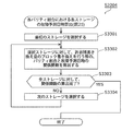
図19は、故障予測日時算出の処理のフローチャートである。先述された図9のS1401では、例えば、この図19の処理がされてもよい。
S1501では、図18の下欄に示される2つのグラフのうちの、左のグラフで示される関数fが特定される。
図18で示されるように、関数fは、日時と、その日時における、アレイ200への書き込み量の累積量との関係の関数である。
S1502では、最初のストレージが、選択ストレージとして選択される。
S1503では、選択された選択ストレージについての、図18の下欄の右のグラフで示される関数gjが特定される。図18で示されるように、関数gjは、アレイ200に対する書き込みの累積量(下欄のグラフの横軸)と、アレイ200に対して、その累積量の書き込みがされた日時における、選択ストレージへの書き込み量の累積量との関係を特定する関数である。
S1504では、選択ストレージにおける保証量が特定される。保証量は、その量のデータ量までの書き込みがされるまでは、その選択ストレージで故障が生じないことが、その選択ストレージのメーカなどにより保証された量である。つまり、保証量は、この量のデータ量だけの書き込みがされた日時(に近い日時)に、故障が生じることが推定される量である。
S1505では、選択ストレージに対して、保証量のデータ量だけの書き込みがされる際における、アレイ200に対する書き込みの累積量が特定される。
S1506では、アレイ200に対する書き込みの累積量が、特定された上述の累積量になる日時が、その選択ストレージの故障予測日時として特定される。
S1507では、全てのストレージの故障予測日時が、上述のS1506で特定されたか否かが判定される。そして、されていると判定された場合には(S1507:YES)、図19の処理が終了する。他方、S1508では、全てのストレージについての処理が終わってないと判定される場合に(S1507:YES)、直前のS1503~S1507での処理での選択ストレージの次のストレージ201が、次のS1504~S1507での処理での選択ストレージとして特定される。
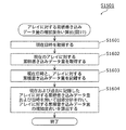
図20は、累積書き込みデータ量の増加度合い算出の処理のフローチャートである。上述された図19のS1501では、例えば、この図20の処理がされてもよい。
S1601では、現在の日時が取得される。なお、例えば、アレイ管理装置10に設けられた、現在の日時を計時する時計から、計時された、現在の日時が取得されてもよい。
S1602では、アレイ200に対する書き込みの、現在における累積量が取得される。なお、例えば、アレイ200などの、アレイ管理装置10の外部に設けられた所定の記憶部により、この累積量が記憶されて、記憶された累積量が、アレイ管理装置10へと取得されてもよい。
S1603では、アレイ管理装置10の記憶領域に、取得された、現在の日時と、アレイ200への書き込みの、現在の累積量とが、互いに対応付けて記憶される。
図18の下欄の2つのグラフのうちの左側のグラフにおける、それぞれの丸印は、アレイ管理装置10の記憶領域において対応付けて記憶された、日時、および、その日時における、アレイ200に対する書き込みの累積量を示す。
S1604では、それぞれの丸印での日時および累積量に基づいて、先述の関数f(図18の左のグラフを参照)が特定される。なお、この特定の処理としては、従来技術における、この種の処理における技術(回帰分析の処理など)が用いられてもよい。
図21は、ストレージに対する累積書き換え量の増加度合い算出の処理のフローチャートである。先述された図19のS1503では、この図21の処理がされてもよい。
S1701では、アレイ200に対する書き込みの、現在における累積量が取得される。S1702では、選択ストレージ(先述)に対する書き込みの、現在の累積量が取得される。なお、例えば、S1702で取得されるこの累積量が、選択ストレージに設けられた所定の記憶部により記憶されて、この記憶部により記憶された累積量が、アレイ管理装置10へと取得されてもよい。
S1703では、S1701で取得された累積量と、S1702で取得された累積量とが、それぞれ、アレイ管理装置10の記憶領域に記憶される。
S1704では、選択ストレージの関数gj(図18の右のグラフ参照)が特定される。なお、この特定の処理では、例えば、S1604での、関数fの特定の処理と同様に、回帰分析の技術などが用いられてもよい。
図22は、3つの故障予測関数のデータのグラフを示す図である。
図示されるように、ストレージjの故障予測関数は、「関数f×関数gj」(関数fと関数gjの合成関数)である。そして、互いに異なるストレージ201での故障予測関数は、通常は、互いに異なる関数である。また、図示されるように、例えば、互いに異なるストレージ201の保証量(先述)は、互いに異なってもよい。
図23は、同時故障発生のイメージ図である。
図23では、同時故障が発生する第1のケースを示す上段の欄と、第2のケースを示す中断の欄と、第3のケースを示す下段の欄とが示される。
(変更処理の具体例)
図24は、同時故障回避の処理のフローチャートである。図9のS1404では、例えば、この図24の処理がされてもよい。
図24は、同時故障回避の処理のフローチャートである。図9のS1404では、例えば、この図24の処理がされてもよい。
S1901では、それぞれのストレージ201における、適切(最適)なパリティ割合201rが算出される。
S1902では、情報101Iが作成される。作成される情報101Iは、その情報での、図5の表における、それぞれのストレージ201でのパリティ割合が、算出された、そのストレージ201での適切(最適)なパリティ割合201rである情報である。
S1903では、それぞれのストライプについて、適宜、スワップの処理がされる。これにより、それぞれのストレージ201のそれぞれのブロック1xB2について、そのブロック1xB2が、データのブロック1xB2dであるか、パリティのブロック1xB2pであるかが、作成された情報101I(図5参照)に沿ったものにされて、それぞれのストレージ201のデータ構造が、作成された情報101Iでのデータ構造にされる。
S1904では、作成された情報101Iが、この図24の処理がされる以前に、パリティ割合管理部101により記憶される情報101I(図8参照)に対して上書きされて、この上書きがされて以後は、パリティ割合管理部101により、作成された新しい情報101Iが記憶される。
図25は、最適パリティ割合算出の処理のフローチャートである。図24のS1901では、例えば、この図25の処理がされてもよい。
S2001では、関数f(先述の図18の左のグラフ参照)が特定される。S2002では、それぞれのストレージ201の許容残書き換え量が特定される。
図26は、各ストレージの許容残書き換え量算出の処理のフローチャートである。図25のS2002では、例えば、この図26の処理がされてもよい。
S2101では、最初のストレージが、選択ストレージとして選択される。S2102では、選択ストレージの保証量が取得される。S2103では、選択ストレージに対する書き込みの、現在における累積量が取得される。S2104では、取得された保証量から、現在の累積量が減じられた量が、許容残書き換え量として特定される。
S2105では、全ストレージ201の処理が終了したか否かが判定される。終了したと判定される場合には(S2105:YES)、図26の処理が終了する。一方で、S2106では、終了していないと判定される場合に(S2106:NO)、選択ストレージとして、次のストレージ201が選択される。
S2003(図26)では、関数が特定される。特定される関数は、ストレージ201における、パリティ割合201rと、そのパリティ割合201rでの、そのストレージ201への書き込み量との間の関係を特定する関数である(図33参照)。
図27は、ストレージのパリティ割合とブロック書き換え量との処理のフローチャートである。図25のS2003では、例えば、この図27の処理がされてもよい。
図28は、データブロック同時書き換えの説明図である。
図28の表では、アレイ200への書き込みに際における第1のパターンが上欄で示され、第2のパターンが中欄で示され、第3のパターンが下欄で示される。第1のパターンでは、1個のストレージ201(ストレージ3)に、パリティの書き込みがされると共に、1個のストレージ201(ストレージ0)に、データの書き込みがされる。第2のパターンでは、1個のストレージ201(ストレージ3)に、パリティの書き込みがされると共に、2個のストレージ201(ストレージ0、1)に、データの書き込みがされる。第3のパターンでは、1個のストレージ201(ストレージ3)に、パリティの書き込みがされると共に、3個のストレージ201(ストレージ0~2)に、データの書き込みがされる。
図29は、同時書き換えデータブロック数と、保存データ量との関係図である。
それぞれのパターンでの、アレイ200への書き込みでの、書き込みがされるデータ量は、例えば、図29で示される通りである。S2201(図27)では、頻度の情報が取得される。取得される、頻度の情報は、アレイ200への書き込みとして、第1のパターンの書き込みが生じる第1の頻度(確率)と、第2のパターンの書き込みが生じる第2の頻度(確率)と、第3のパターンの書き込みが生じる第3の頻度(確率)とをそれぞれ特定する。
図30は、データブロック同時書き換え発生頻度情報管理テーブルの例である。
図30では、取得される情報により、第1の頻度として25%が特定され、第2の頻度として40%が特定され、第3の頻度として35%が特定されるケースが示される。
図31は、データブロック同時書き換え発生頻度に応じたデータの割り当ての図である。
アレイ200に対して書き込みがされるのに際して、第1、第2、第3のパターンでの書き込みが、上述の第1、第2、第3の頻度(25%、40%、35%)で行われる。そして、それぞれのパターンでの書き込みでは、1MB、2MB、3MBの書き込みがされる。
このため、第1、第2、第3のパターンで書き込みがされるデータ量の比は、「25%×1MB:40%×2MB:35%×3MB」=「25MB:80MB:105MB」である。
このため、アレイ200に対して、あるデータ量(2520MB)の書き込みがされる際における、第1、第2、第3のパターンでの書き込みのデータ量は、2520MB×(25MB/(25MB+80MB+105MB))=2520MB×(25MB/210MB)=300MB、2520MB×(80MB/210MB)=960MB、2520MB×(105MB/210MB)=1260MBである(図31の最下部を参照)。
つまり、第1、第2、第3のパターンでの書き込みがされるストライプの数は、300MB/1MB=300個、960MB/2MB=480個、1260MB/3MB=420個である。
こうして、アレイ200に対する書き込みのデータ量(250MB)から、第1、第2、第3のパターンでの書き込みがされるストライプ数(300個、480個、420個)が特定される。
S2202(図27)では、アレイ200に対して、単位データ量(図31の2520MB参照)の書き込みがされる際における、第1、第2、第3のパターンでの書き込みがされる第1、第2、第3のストライプ数(300個、480個、420個を参照)が特定される。
そして、第1のパターンで、第1のストライプ数(300個)の書き込みがされるのに際して、ストレージ201に対して行われる書き込みの回数は、以下の通りである。
なお、以下では、説明の便宜上、ストレージ201のパリティ割合201rが、x%と略記される。
つまり、第1のストライプ数(300個)のうちの、(100-x)%の割合の個数(300個×(100-x)%)のストライプについては、それらのストライプのうちのそれぞれのストライプにおける、そのストレージ201のブロック1xB2は、データのブロックである。
そして、第1のパターンでの書き込みでは、図30の上欄に示されるように、ストライプに含まれる、3つの、データのブロックのうちの1つのブロックにのみ、書き込みがされる。
このため、それらの、上述された、(300個×(100-x)%)の個数のストライプのうちの、1/3の個数{(300個×(100-x)%)/3}のストライプの書き込みにおいて、そのストレージ201への書き込みがされる。
図32は、データブロックにおける書き換え処理発生率の説明図である。
なお、上述の1/3の点については、適宜、この図32も参照されたい。
一方で、上述された、第1のストライプ数(300個)のストライプのうちの、x%の割合の個数(300個×x%)のストライプについては、そのストライプにおける、そのストレージ201のブロック1xB2が、パリティのブロック1xB2pである。
このため、これら、(300個×x%)の個数のストライプの書き込みでは、必ず、そのストレージ201への書き込みがされる。
このため、第1のストライプ数(300個)のストライプのうちの、「{(300個×(100-x)%)/3} + (300個×x%)」の個数のストライプの書き込みにおいて、そのストレージ201への書き込みがされる。
こうして、アレイ200に対して、単位データ量(2520MB参照)の書き込みがされる際に生じる、第1のパターンでの、ストレージ201への書き込みの回数W1(x)が、上述された、「{(300個×(100-x)%)/3} + (300個×x%)」と特定される。
同様にして、第1のパターンでの、ストレージ201への書き込みの回数W2(x)、および、第3のパターンでの、ストレージ201への書き込みの回数W3(x)も特定される。
これにより、2520MBの書き込みがされる際における、ストレージ201への書き込みの回数J(x)が、J(x)=W1(x)+W2(x)+W3(x)と特定される。
図33は、パリティ割合201r(上述のx)と、回数J(x)だけの書き込みで書き込まれるデータ量との関係を特定する関数K(x)のグラフを示す図である。先述のJ(X)が特定されることにより、このK(x)が特定される。
図34は、同時書き換えデータブロック数を考慮したブロック書き換え量を示す図である。
すなわち、上述された、第1のパターンでの回数であるW1(x)は、図34の上欄の左、中央、右の3つのグラフのうちの左のグラフでの関数である。そして、W2(x)は、中央のグラフでの関数であり、W3(x)は、右のグラフでの関数である。
そして、下欄のグラフの関数は、上述された、J(x)=W1(x)+W2(x)+W3(x)から特定されるK(X)である。S2204~S2206(図27)では、上述のW1(x)、W2(x)、W3(x)が特定される。S2207では、特定された、これらW1(x)、W2(x)、W3(x)から、上述のK(x)、つまり、図34の下欄のグラフの関数が特定される。
図35Aは、複数のストレージ201(ストレージ0~3)でのパリティ割合201rの組合わせを示す図である。
図35Bは、図35Aの組合わせの状態でのアレイ200を示す図である。
図35Cは、パリティ割合201rの組合わせが、図35Aの組合わせである際における、それぞれのストレージ201での、書き込みがされるデータ量を示す図である。
図35Bの組合わせでは、図35Cで示されるように、ストレージ0~4での、書き込みのデータ量(上述のK(x))の比が、「1:1:1:3」である。
図36は、図35Aでの組合わせとは異なる組合わせを示す図である。
アレイ管理装置10により特定される適切な組合わせは、通常は、図35Aで示されるような組合わせでなく、図36で示されるような組合わせである。
図37は、3つのグラフを示す図である。
上段のグラフは、パリティ割合201rと、書き込みのデータ量との間の関係を示すグラフであり、上述のK(x)のグラフである(図34の下欄を参照)。中段のグラフは、パリティ割合201rと、アレイ200に対する書き込みのデータ量との間の関係を示すグラフ(L(x))である。上段のグラフ(J(x))から、この、中段のグラフ(L(x))が特定される。
下段のグラフは、パリティ割合201rと、ストレージ201の故障予測日時との関係を示すグラフ(M(x))である。中段のグラフ(L(x))から、この、下段のグラフ(M(x))が特定される。
S2004(図25)では、特定された上述のJ(x)から特定される、このM(X)に基づいて故障予測日時が特定される。つまり、例えば、それぞれのストレージ201での、そのストレージ201が、それぞれのパリティ割合201rのときにおける故障予測日時が特定される。
図38は、4つのグラフを示す図である。すなわち、S2004では、図38の4つのグラフが特定される。
図39は、各パリティ割合における各ストレージの故障予測日時算出の処理のフローチャートである。図25のS2004では、例えば、この図39の処理がされてもよい。
図26の処理では、それぞれのストレージ201を対象ストレージとして、S3302の処理が行われる。
S3302(図39)では、それぞれのストレージ201(対象ストレージ)についての、それぞれのパリティ割合201rでの故障予測日時が特定される。
S2005(図25)では、アレイ200に含まれる複数のストレージ201のパリティ割合201rの組合わせのそれぞれについて、その組合わせでの、それぞれのストレージ201の故障予測日時が特定される。つまり、S2005では、それぞれの組合わせについて、その組合わせにおける、複数の故障予測日時が特定される。
そして、S2005では、複数の組合わせ(上述)のうちから、特定される、複数の故障予測日時が、最も適切である組合わせを特定する(図38の処理1G、先述の図10Bなどを参照)。つまり、複数の組合わせから、最も適切な組合わせが特定される。なお、最も適切である組合わせでの、特定される複数の故障予測日時においては、例えば、先述された第1のストレージαの故障予測日時(図10Bの日時1t)と、第2のストレージβの故障予測日時1Bとの間の差1F1が、最大でもよい。
そして、図24のS1903~S1904では、特定された、最適である、パリティ割合の組合わせに基づいて、先述された処理が行われる。つまり、例えば、このS1903~S1904では、アレイ200の動作が制御されてもよい。つまり、制御がされた動作では、アレイ200における、それぞれのストレージ201でのパリティ割合が、特定された、最適な組合わせでの、そのストレージ201のパリティ割合と同じ割合でもよい(先述された、S1903、S904の説明などを参照)。
(数式等による説明)
以下では、より詳細な説明がされる。
以下では、より詳細な説明がされる。
まず、記号の説明がされる。以下の説明で、記号「Nstripe」は、アレイ200におけるストライプ1xB1の数(ストライプ数)を示す。つまり、ストライプ番号iは、0~Nstripe-1の値と取りうる。また、記号「Nstorage」は、アレイ200におけるストレージ201の数(ストレージ数)を示す。ただし、スペアストレージは含まない。つまり、ストレージ番号jは、0~Nstorage-1の値を取りうる。また、記号「Ndata」は、各ストライプにおける、データブロック(ブロック1xB2d)のストレージ数(図4等では3個)を示す。また、記号「Nparity」は、各ストライプにおける、パリティブロック(ブロック1xB2p)のストレージ数を示す。つまり、RAID5では、Nparity=1であり、また、RAID6ではNparity=2である。ここで、Nstripe、Nstorage、Ndata、Nparityは、一般に、アレイの新規構築時に決定し、運用中は変化しない。例として、Nstorage=4、Ndata=3、Nparity=1とする。
図3などにおいて、それぞれのブロック1xB2は、Bk○△という形で表現される。ここで、○はストライプ番号であり、△はストレージ番号である。
図4、図7、図5などにおいて、データに対応するブロック(データのブロック1xB2d)は、BD○#という形で表現される。なお、ここで、「#」は、「各ストライプにおけるデータブロックに対応するストレージ番号」である。一方、パリティに対応するブロック(ブロック1xB2p)は、BP○$という形で表現される。ここで、「$」は、「各ストライプにおけるパリティブロックに対応するストレージ番号」である。
次に、図18の2つのグラフのうちの、左のグラフについて述べる。
まず、記号の説明がされる。記号「Tnow」は、現在時刻を示す。記号「Dnow」は、アレイに対する、現在の累積データ書き込み量を示す。記号「Tj」は、アレイにおいて、ストレージjが破損すると予測される日時を示す。記号「Dj」は、日時Tjにおける、アレイに対する累積データ書き込み量を示す。記号「tj」は、現在時刻からストレージjの故障予測日時までの所要時間(Tj=Tnow+tj)を示す。記号「dj」は、日時Tjにおける、アレイに対する累積データ書き込み量(Dj=Dnow+dj)を示す。
ここで、Tnowは取得可能である。また、Dnowは、予め、過去のデータ書き込み量を記録しておく仕組みがアレイ管理装置10に設けられ、それを利用し、取得可能とする。そして、以下の説明では、tj、djを求めることが述べられる。これらtj、djより、Tj、Djを決定することが可能である。
故障予測関数fが、線形とすると、以下の式での表現がされる。ここで、aは係数である。

係数aについては、「過去のデータ書き込み量」と、「その時点の日時」の記録を用いた回帰分析等により決定される。
次に、図18の右のグラフについて説明される。
まず、記号の説明がされる。記号「Wjnow」は、ストレージjに対する現在の累積ブロック書き換え量を示す。記号「Wjmax」は、ストレージjに対するブロック書き換え量の保証値を示す。記号「wj」は、ストレージjに対する許容残書き換え量(wj=Wjmax-Wjnow)を示す。ここで、Wjnowは、予め、過去のブロック書き換え量を記録しておく仕組みをアレイ管理装置10に設けておき、それを利用し、取得可能とする。Wjmaxは、メーカ保証値、あるいは、加速度試験などにより、予め決定するとする(S.M.A.R.T.(Self-Monitoring, Analysis and Reporting Technology)を用いてもよい)。Wjnow、Wjmaxが決定可能なので、wjも決定可能である。
故障予測関数gjが線形とすると、以下の式で表現される(ここで、bjは係数)。

係数bjは、ストレージごとに異なる。「過去のブロック書き換え量」と、「その時点のアレイに対するデータ書き込み量」の記録を用いた回帰分析等により決定される。
Wjnow、Wjmax、a、bjが決定されることで、上述の式(1)(2)を用いて、tjを算出できる。
例として、以下の場合を考える(データ量の単位をMB、時間の単位をhとする)。アレイに対する書き込みデータ量は、平均して1時間あたり、400MB(a=400)である。アレイに対して、10MBのデータ書き込みが発生する際に、ストレージjに対して、4MBのブロック書き換えが発生するとする(bj=0.4)。ストレージjにおける許容残書き換え量は40000MB(wj=40000)である。式(1)、(2)より、dj=100000、tj=250であり、つまりストレージjは、250時間後に破損するという予測が算出できる。全ストレージに対して、同様に、tjを算出する。なお、故障予測関数f、gjは非線形でも良い。
次に、図10A~図10Cについて述べられる。
まず、記号の説明がされる。記号「M」は、冗長化アレイにおける最大許容故障台数を示す。つまり、RAID5ではM=1であり、RAID6ではM=2である。RAID5、6の場合には、Mは、Nparityと一致する。記号「Tα」は、アレイにおいて、最初にストレージが破損すると予測される日時を示す。ここで、最初に破損すると予測されているストレージをαとする。記号「Tβ」は、アレイにおいて、M+1番目にストレージが破損する(つまり、アレイが破損する)と予測される日時を示す。ここで、M+1番目に破損すると予測されているストレージをβとする。記号「Δαβ」は、ストレージαと、ストレージβの破損の間隔(Δαβ=Tβ-Tα)を示す。
ここで、Mは、一般に、アレイの新規構築時に決定し、運用中は変化しない。Tα、Tβは、全ストレージについてTjを算出後、並び替えることで、決定可能である。そして、Tα、Tβが決定可能なので、Δαβも決定可能である。そして、Δαβが、所定値以内である場合、同時故障発生の危険性があると判断する。
続けて、図10Cについて述べられる。
まず、記号の説明がされる。記号「Tγ」は、アレイにおいて、x番目にストレージが破損すると予測される日時を示す。ここで、x番目に破損すると予測されているストレージをγとする。xは、2~Mの値を取りうる。記号「Tγ1」は、アレイにおいて、x-1番目にストレージが破損すると予測される日時を示す。ここで、x-1番目に破損すると予測されているストレージをγ1とする。記号「Tγ2」は、アレイにおいて、x+1番目にストレージが破損すると予測される日時を示す。ここで、x-2番目に破損すると予測されているストレージをγ2とする。記号「Δγγ1」は、ストレージγと、ストレージγ1の破損の間隔の時間(Δγγ1=Tγ-Tγ1)を示す。記号「Δγγ2」は、ストレージγと、ストレージγ2の破損の間隔の時間(Δγγ2=Tγ2-Tγ)を示す。
ここで、xの値は2~Mの整数値を取りうる。xが決定すれば、Tγ、Tγ1、Tγ2、Δγγ1、Δγγ2も決定可能である。任意のxについて、それぞれΔγγ1、Δγγ2を算出する。そして、Δγγ1またはΔγγ2が、所定値以内である場合、同時故障発生の危険性があると判断する。
次に、図28、図30について述べられる。
記号の説明がされる。記号「v」は、同時書き換えデータブロック数を示す。vは、1~Ndataの値を取りうる。
以下の説明では、まず、vが、任意の値を取る場合について説明する。その後に、vの発生頻度を用いて、全てのvについて算出した結果を統合して考える。
次に、図29について述べられる。
まず、記号の説明がされる。記号「BK」は、ブロックサイズ(ここでは固定とするが、可変でもよい)を示す。記号「Cv」は、同時書き換えデータブロック数vにおいて、1回のストライプ書き込みで保存可能なデータ量を示す。
Cvは、以下の式により算出される。

次に、図31について述べられる。
まず、記号の説明がされる。記号「Rv」は、同時書き換えデータブロック数vにおける、書き込みストライプ数を示す。記号「Pv」は、同時書き換えデータブロック数vにおける、同時書き換え発生頻度。(Pvは0~1の値を取りうる。また、全同時書き換えデータブロック数における合計値はRAID5なら1、RAID6なら2となる)を示す。
ここで、媒介変数cを用いて、以下の式での表現ができる。

受付データのデータ量をdとすると、このdは、以下の式で算出される。
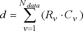
つまり、(3)、(4)より、下記の通りである。

例として、以下の場合を考える(データ量の単位をMBとする)。つまり、Ndata=3、P1=0.25、P2=0.4、P3=0.35、BK=1、d=2520の場合が考えられる。
式(6)を解くと、c=1200となる。つまり、R1=300、R2=480、R3=420と算出することができる。
次に、図32について述べられる。まず、記号の説明がされる。記号「Qv」は、同時書き換えデータブロック数vにおける、データブロックにおける書き換え処理発生率を示す。
Qvは、以下の式により算出可能である。

例として、Ndata=3、v=1なら、Q1=1/3である。
次に、図35A~図35Cについて述べられる。
同時書き換えデータブロック数vにおいて、Rv個のストライプに対して書き込みを行うことを考える。ここで、各ストレージに対してブロック書き換えが発生する。
まず、各ストレージにおけるパリティ割合が0%または100%である場合を考える。
最初に、記号の説明がされる。記号「wvdata」は、同時書き換えデータブロック数vにおいて、Rv個のストライプに対して書き込みを行う際に、「パリティ割合0%」のストレージに対して発生するブロック書き換え量を示す。記号「wvparity」は、同時書き換えデータブロック数vにおいて、Rv個のストライプに対して書き込みを行う際に、「パリティ割合100%」のストレージに対して発生するブロック書き換え量を示す。
wvdata、wvparityは、以下の式により算出される。


例として、以下の場合を考える(データ量の単位をMB)。つまり、Ndata=3、v=1、BK=1、Rv=300である場合が考えられる。
式(8)、(9)より、wvdata=100、wvparity=300、つまりアレイに対して300MBのデータ書き込みを行う際に、パリティ割合0%のストレージに対するブロック書き換え量は100MBであるといえる。
次に、図6、33、36について述べられる。
パリティ割合が0%および100%以外の場合について考える。
まず、記号の説明がされる。記号「wvr」は、同時書き換えデータブロック数vにおいて、Rv個のストライプに対して書き込みを行う際に、「パリティ割合r」のストレージに対して発生するブロック書き換え量。以下の式により算出される(ただしrは0~1の範囲を示す)。
wvrは、以下の式により算出される。

例として、wvdata=100、wvparity=300、R=0.3とすると、wvr=160と算出できる。
次に、図34について述べられる。ここでは、前記で各vについて算出した結果を統合して考える。まず、記号の説明がされる。記号「wr」は、「パリティ割合r」のストレージに対して発生するブロック書き換え量を示す。
ここで、wrは、各同時書き換えデータブロック数における合計値となる。つまり、wrは、以下の式により算出される。

・・・(11)
(10)より、

である。
(8)、(9)より、

である。
(7)より、

と表せる。
例として、以下の場合を考える(データ量の単位をMB)。つまり、Ndata=3、R1=300、R2=480、R3=420、BK=1である場合が考えられる。
式(14)への代入がされると、以下の式となる。

上記の式に、例えばr=0.3を代入すると、「アレイに対して2520MBの書き込みを行う際の、パリティ割合30%のストレージに対するブロック書き換え量」が、wr=948として算出できる。
さらに、(14)に対して(4)を適用すると

・・・(16)
である。(6)より、

なので、

・・・(18)
である。整理すると

・・・(19)
である。ここで、

なので、
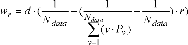
・・・(21)
である。
つまり、式(21)より、r、d、Ndata、およびそれぞれの同時書き換えデータブロック数vにおける、同時書き換え発生頻度Pvが決定すれば、wrを決定することができる。
ここで、

・・・(22)
をYとおく。Yの値は、同時書き換え発生頻度PvとNdataにより決定する。Ndataは、アレイ新規構成時に決定し、Pvは、ストレージに対して書き込みを行うアプリケーションやシステムなど外部の特性により決定する(シーケンシャルライト、ランダムライトの割合、その時のデータ量など)。つまり、Yは、アレイを構成する各ストレージのパリティ割合の影響を受けない。
・・・(22)
をYとおく。Yの値は、同時書き換え発生頻度PvとNdataにより決定する。Ndataは、アレイ新規構成時に決定し、Pvは、ストレージに対して書き込みを行うアプリケーションやシステムなど外部の特性により決定する(シーケンシャルライト、ランダムライトの割合、その時のデータ量など)。つまり、Yは、アレイを構成する各ストレージのパリティ割合の影響を受けない。
次に、図37について述べられる。
ストレージjのパリティ割合をrに再設定することを考える。まず、記号の説明がされる。記号「Tjr」は、ストレージjのパリティ割合をrに再設定した時に、アレイにおいて、ストレージjが破損すると予測される日時を示す。記号「Djr」は、日時Tjrにおける、アレイに対する累積データ書き込み量を示す。記号「tjr」は、現在時刻から、ストレージjのパリティ割合をrに再設定した時のストレージjの故障予測日時までの所要時間(Tjr=Tnow+tjr)を示す。記号「djr」は、日時Tjrにおける、アレイに対する累積データ書き込み量を示す(Djr=Dnow+djr)。
ストレージjのパリティ割合をrに変更することで、故障予測日時を変化させることができる。なお、故障予測関数fについては影響を受けない。ここで、式(20) においてwr=wj、d=djrとすることで、djrを算出できる。

変形すると

・・・(24)
である。さらに、故障予測関数fを用いて故障予測日時を算出する。(1)より、

・・・(25)
である。
例として、以下の場合を考える(データ量の単位をMB)。つまり、Ndata=3、P1=0.25、P2=0.4、P3=0.35、wj=40000である場合が考えられる。
式(24)への代入がされると、以下の式が成り立つ。

・・・(26)
さらに、a=400とすると、
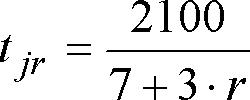
・・・(27)
という式が成り立つ。
上記の式に、例えばr=0.3を代入すると、「ストレージjのパリティ割合を30%とした際の、故障予測日時(現在日時からの経過時間)がtjr=266、つまり266時間後として算出できる。そして、例えば、パリティ割合を0%に変更すればtjr=300、つまり故障予測日時を34時間変化させることができる。
最後に、図38について述べられる。図38では、全てのストレージに対して、故障予測日時までの所要時間tjrと、パリティ割合rの関係関数を導出することが示される。
(その他)
なお、例えば、次のようでもよい。
なお、例えば、次のようでもよい。
すなわち、アレイ200により保持されるデータの消失は、第1のストレージαが故障する日時1tが第1の日時1t1である場合には、発生し難く、第2の日時1t2である場合には発生し易く、第1のストレージαは、第1のストレージαにより記憶されるデータ(領域201d参照)とパリティ(領域201p参照)との全体(領域201A参照)に占める、パリティの割合であるパリティ割合201rが、第1の割合201r1である場合と、第2の割合201r2である場合とがあるストレージであり、第1のストレージαの故障の日時1tは、第1の割合201r1である場合には、消失が発生し難い第1の日時1t1であり、第2の割合201r2である場合には、発生し易い第2の日時1t2であり、判断部100xは、予め定められた2つの割合のうちの一方の割合を第1の割合201r1と特定し、他方の割合を第2の割合201r2と特定し、変更制御部100yは、第1のストレージαでの割合201rを、特定された一方の割合(第1の割合201r1)にさせ、特定された他方の割合(第2の割合201r2)にはさせない制御をしてもよい。
そして、消失が発生し難い第1の日時1t1は、アレイ200に含まれる、第1のストレージαとは別の第2のストレージβが故障する日時1Bから閾値1F2以上に離れた日時であり、消失が発生し易い第2の日時1t2は、第2のストレージβが故障する日時1Bから閾値1F2以内の日時でもよい。
これにより、データの消失の発生が防げる。
しかも、単なる、パリティの割合に応じた処理がされるだけで済み、処理が簡単にできる。
なお、本実施例のアレイ管理装置は、典型的には半導体集積回路であるLSIとして実現される。これらは個別に1チップ化されてもよいし、一部またはすべてを含むように1チップ化されても良い。ここではLSIとしたが、集積度の違いにより、IC、システムLSI、スーパーLSI、ウルトラLSIと呼称されることもある。
また、集積回路化の手法はLSIに限るものではなく、専用回路または汎用プロセッサで実現しても良い。LSI製造後に、プログラムすることが可能なFPGA(Field Programmable Gate Array)や、LSI内部の回路セルの接続や設定を再構成可能なリコンフィギュラブル・プロセッサを利用しても良い。
さらには、半導体技術の進歩または派生する別技術によりLSIに置き換わる集積回路化の技術が登場すれば、当然、その技術を用いて機能ブロックの集積化を行っても良い。バイオ技術の適応などが可能性として有り得る。
さらに加えて、本実施例の~装置を集積化した半導体チップと、画像を描画するためのディスプレイとを組み合せて、様々な用途に応じた描画機器を構成することができる。携帯電話やテレビ、デジタルビデオレコーダ、デジタルビデオカメラ、カーナビゲーション等における情報描画手段として、本発明を利用することが可能である。ディスプレイとしては、ブラウン管(CRT)の他、液晶やPDP(プラズマディスプレイパネル)、有機ELなどのフラットディスプレイ、プロジェクターを代表とする投射型ディスプレイなどと組み合わせることが可能である。
なお、上記各実施の形態において、各構成要素は、専用のハードウェアで構成されるか、各構成要素に適したソフトウェアプログラムを実行することによって実現されてもよい。各構成要素は、CPUまたはプロセッサなどのプログラム実行部が、ハードディスクまたは半導体メモリなどの記録媒体に記録されたソフトウェアプログラムを読み出して実行することによって実現されてもよい。ここで、上記各実施の形態のアレイ管理装置などを実現するソフトウェアは、次のようなプログラムである。
すなわち、このプログラムは、複数のストレージが構成するアレイを管理するコンピュータに、前記複数のストレージのうち少なくとも2台のストレージが同時期に故障することによって、前記アレイが保持するデータが消失する可能性があるか否かを判断する判断ステップと、前記アレイが保持する前記データが消失する可能性があると判断された場合には、前記少なくとも2台のストレージのうちの少なくとも一つの故障時期を変更する、故障時期変更ステップとを実行させるためのコンピュータプログラムなどである。
本発明のアレイ管理装置は、様々な用途に利用可能である。例えば、携帯電話や携帯音楽プレーヤー、デジタルカメラ、デジタルビデオカメラ等の電池駆動の携帯表示端末や、テレビ、デジタルビデオレコーダ、カーナビゲーション等の高解像度の情報表示機器におけるメニュー表示やWebブラウザ、エディタ、EPG、地図表示等における情報表示手段として利用価値が高い。
将来、複数のストレージが同時期に故障することによって、アレイが保持するデータが消失する可能性があると判断した場合には、同時故障する可能性がある複数のストレージの故障時期をずらす。このことで、アレイが保持するデータ消失を防ぐことができる。
1xB2、1xB2d、1xB2p ブロック
10 アレイ管理装置
100x 判断部
100y 変更制御部
101 パリティ割合管理部
102 パリティ割合算出部
103 パリティ割合変更部
104 故障予測部
200 アレイ
201 ストレージ
201d 領域
201p 領域
10 アレイ管理装置
100x 判断部
100y 変更制御部
101 パリティ割合管理部
102 パリティ割合算出部
103 パリティ割合変更部
104 故障予測部
200 アレイ
201 ストレージ
201d 領域
201p 領域
Claims (8)
- 複数のストレージが構成するアレイを管理するアレイ管理装置であって、
前記複数のストレージのうち少なくとも2台のストレージが同時期に故障することによって、前記アレイが保持するデータが消失する可能性があるか否かを判断する判断部と、
前記アレイが保持する前記データが消失する可能性があると判断された場合には、前記少なくとも2台のストレージのうちの少なくとも一つの故障時期を変更する、故障時期変更部と、
を備えるアレイ管理装置。 - 前記故障時期変更部は、前記各ストレージに対して書き込む、パリティとデータとの割合を変更することによって、前記少なくとも2台のストレージのうちの少なくとも一つの故障時期を変更する、
請求項1記載のアレイ管理装置。 - 前記判断部は、
前記複数のストレージのうち少なくとも2台のストレージが同時期に故障する可能性があるか否かを判断する同時故障判断部と、
前記少なくとも2台のストレージが同時期に故障すると判断された場合に、前記少なくとも2台のストレージが同時期に故障することによって、前記アレイが保持するデータが消失する可能性があるか否かを判断するアレイ故障判断部とを含む
請求項1記載のアレイ管理装置。 - 前記アレイにより保持される前記データの消失は、第1の前記ストレージが故障する日時が第1の日時である場合には、発生し難く、第2の日時である場合には発生し易く、
第1の前記ストレージは、記憶されるデータとパリティとの全体に占める、前記パリティの割合が、第1の割合である場合と、第2の割合である場合とがあるストレージであり、
第1の前記ストレージの前記日時は、前記第1の割合である場合には、消失が発生し難い前記第1の日時であり、前記第2の割合である場合には、発生し易い前記第2の日時であり、
前記判断部は、2つの割合のうちの一方の前記割合を前記第1の割合と特定し、他方の前記割合を前記第2の割合と特定し、
前記故障時期変更部は、第1の前記ストレージでの前記割合を、特定された一方の前記割合にさせ、特定された他方の前記割合にはさせない、
請求項1記載のアレイ管理装置。 - 消失が発生し難い前記第1の日時は、第2の前記ストレージが故障する日時から閾値以上に離れた日時であり、
消失が発生し易い前記第2の日時は、第2の前記ストレージが故障する日時から閾値以内の日時である、
請求項4記載のアレイ管理装置。 - 複数のストレージが構成するアレイを管理する集積回路であって、
前記複数のストレージのうち少なくとも2台のストレージが同時期に故障することによって、前記アレイが保持するデータが消失する可能性があるか否かを判断する判断部と、
前記アレイが保持する前記データが消失する可能性があると判断された場合には、前記少なくとも2台のストレージのうちの少なくとも一つの故障時期を変更する、故障時期変更部と、
を備える集積回路。 - 複数のストレージが構成するアレイを管理するアレイ管理方法であって、
前記複数のストレージのうち少なくとも2台のストレージが同時期に故障することによって、前記アレイが保持するデータが消失する可能性があるか否かを判断する判断ステップと、
前記アレイが保持する前記データが消失する可能性があると判断された場合には、前記少なくとも2台のストレージのうちの少なくとも一つの故障時期を変更する、故障時期変更ステップと、
を含むアレイ管理方法。 - 複数のストレージが構成するアレイを管理するコンピュータに、
前記複数のストレージのうち少なくとも2台のストレージが同時期に故障することによって、前記アレイが保持するデータが消失する可能性があるか否かを判断する判断ステップと、
前記アレイが保持する前記データが消失する可能性があると判断された場合には、前記少なくとも2台のストレージのうちの少なくとも一つの故障時期を変更する、故障時期変更ステップと、
を実行させるためのコンピュータプログラム。
Applications Claiming Priority (2)
| Application Number | Priority Date | Filing Date | Title |
|---|---|---|---|
| JP2011081205 | 2011-03-31 | ||
| JP2011-081205 | 2011-03-31 |
Publications (1)
| Publication Number | Publication Date |
|---|---|
| WO2012132408A1 true WO2012132408A1 (ja) | 2012-10-04 |
Family
ID=46930183
Family Applications (1)
| Application Number | Title | Priority Date | Filing Date |
|---|---|---|---|
| PCT/JP2012/002116 Ceased WO2012132408A1 (ja) | 2011-03-31 | 2012-03-27 | アレイ管理装置、アレイ管理方法、コンピュータプログラム、集積回路 |
Country Status (1)
| Country | Link |
|---|---|
| WO (1) | WO2012132408A1 (ja) |
Cited By (2)
| Publication number | Priority date | Publication date | Assignee | Title |
|---|---|---|---|---|
| WO2015029249A1 (ja) * | 2013-09-02 | 2015-03-05 | 株式会社日立製作所 | ストレージ装置及びそのデータ処理方法 |
| JP2015528174A (ja) * | 2013-06-29 | 2015-09-24 | 華為技術有限公司Huawei Technologies Co.,Ltd. | ストレージアレイを管理する方法及び装置 |
Citations (3)
| Publication number | Priority date | Publication date | Assignee | Title |
|---|---|---|---|---|
| JP2007206993A (ja) * | 2006-02-02 | 2007-08-16 | Fujitsu Ltd | ストレージシステム、制御方法及びプログラム |
| JP2009037304A (ja) * | 2007-07-31 | 2009-02-19 | Hitachi Ltd | Raidレベルを変更する機能を有したストレージシステム |
| JP2010015516A (ja) * | 2008-07-07 | 2010-01-21 | Toshiba Corp | データ制御装置、ストレージシステムおよびプログラム |
-
2012
- 2012-03-27 WO PCT/JP2012/002116 patent/WO2012132408A1/ja not_active Ceased
Patent Citations (3)
| Publication number | Priority date | Publication date | Assignee | Title |
|---|---|---|---|---|
| JP2007206993A (ja) * | 2006-02-02 | 2007-08-16 | Fujitsu Ltd | ストレージシステム、制御方法及びプログラム |
| JP2009037304A (ja) * | 2007-07-31 | 2009-02-19 | Hitachi Ltd | Raidレベルを変更する機能を有したストレージシステム |
| JP2010015516A (ja) * | 2008-07-07 | 2010-01-21 | Toshiba Corp | データ制御装置、ストレージシステムおよびプログラム |
Cited By (7)
| Publication number | Priority date | Publication date | Assignee | Title |
|---|---|---|---|---|
| JP2015528174A (ja) * | 2013-06-29 | 2015-09-24 | 華為技術有限公司Huawei Technologies Co.,Ltd. | ストレージアレイを管理する方法及び装置 |
| US9292220B2 (en) | 2013-06-29 | 2016-03-22 | Huawei Technologies Co., Ltd. | Method, apparatus, and controller for managing storage array |
| US9696938B2 (en) | 2013-06-29 | 2017-07-04 | Huawei Technologies Co., Ltd. | Method, apparatus, and controller for managing storage array |
| US9747050B2 (en) | 2013-06-29 | 2017-08-29 | Huawei Technologies Co., Ltd. | Method, apparatus, and controller for managing storage array |
| US10095429B2 (en) | 2013-06-29 | 2018-10-09 | Huawei Technologies Co., Ltd. | Method, apparatus, and controller for managing storage array |
| WO2015029249A1 (ja) * | 2013-09-02 | 2015-03-05 | 株式会社日立製作所 | ストレージ装置及びそのデータ処理方法 |
| US8990523B1 (en) | 2013-09-02 | 2015-03-24 | Hitachi, Ltd. | Storage apparatus and its data processing method |
Similar Documents
| Publication | Publication Date | Title |
|---|---|---|
| CN102156738B (zh) | 数据块处理方法、数据块存储设备及系统 | |
| CN111858130B (zh) | 用于拆分盘集的方法、设备和计算机程序产品 | |
| CN105573681B (zh) | 一种ssd盘片内部raid组建方法及系统 | |
| EP2272001B1 (en) | Dynamically quantifying and improving the reliability of distributed data storage systems | |
| US9129699B2 (en) | Semiconductor storage apparatus and method including executing refresh in a flash memory based on a reliability period using degree of deterioration and read frequency | |
| CN102929786B (zh) | 非易失性存储设备集合的易失性存储器表示 | |
| US20120317437A1 (en) | Ranking Service Units to Provide and Protect Highly Available Services Using the Nway Redundancy Model | |
| US8904097B2 (en) | Measure of health for writing to locations in flash | |
| EP3579108B1 (fr) | Contrôleur de partage de ressources d'une plate-forme informatique et procédé associé de partage des ressources | |
| US9798476B2 (en) | Skewing expected wearout times of memory devices | |
| CN105659329A (zh) | 用于固态存储器中经改善电压分布的编程方案 | |
| US10846143B2 (en) | Predicting capacity of shared virtual machine resources | |
| US20200117386A1 (en) | Method and apparatus for calculating storage system available capacity | |
| Butler et al. | CMS Phase II upgrade scope document | |
| CN102096558A (zh) | 一种数据的存储方法和装置 | |
| CN110058789B (zh) | 用于管理存储系统的方法、存储系统以及计算机程序产品 | |
| WO2012132408A1 (ja) | アレイ管理装置、アレイ管理方法、コンピュータプログラム、集積回路 | |
| US20190220212A1 (en) | Method of storage allocation, electronic device, storage system and computer program product | |
| US20170255400A1 (en) | Managing storage devices having a lifetime of a finite number of operations | |
| CN104050975A (zh) | 分段式读取-修改-写入操作 | |
| CN105528303A (zh) | 用于管理存储系统的方法和装置 | |
| CN115878450A (zh) | 执行测试任务的方法及装置 | |
| US20250077475A1 (en) | Compaction method and device for sorted strings table files | |
| US20230229342A1 (en) | Read-disturb-based read temperature identification system | |
| US11023149B1 (en) | Doubly mapped cluster contraction |
Legal Events
| Date | Code | Title | Description |
|---|---|---|---|
| 121 | Ep: the epo has been informed by wipo that ep was designated in this application |
Ref document number: 12764773 Country of ref document: EP Kind code of ref document: A1 |
|
| NENP | Non-entry into the national phase |
Ref country code: DE |
|
| 122 | Ep: pct application non-entry in european phase |
Ref document number: 12764773 Country of ref document: EP Kind code of ref document: A1 |
|
| NENP | Non-entry into the national phase |
Ref country code: JP |