WO2012132459A1 - 車載用充電装置 - Google Patents
車載用充電装置 Download PDFInfo
- Publication number
- WO2012132459A1 WO2012132459A1 PCT/JP2012/002197 JP2012002197W WO2012132459A1 WO 2012132459 A1 WO2012132459 A1 WO 2012132459A1 JP 2012002197 W JP2012002197 W JP 2012002197W WO 2012132459 A1 WO2012132459 A1 WO 2012132459A1
- Authority
- WO
- WIPO (PCT)
- Prior art keywords
- input
- input current
- value
- straight line
- control unit
- Prior art date
- Legal status (The legal status is an assumption and is not a legal conclusion. Google has not performed a legal analysis and makes no representation as to the accuracy of the status listed.)
- Ceased
Links
Images





Classifications
-
- B—PERFORMING OPERATIONS; TRANSPORTING
- B60—VEHICLES IN GENERAL
- B60L—PROPULSION OF ELECTRICALLY-PROPELLED VEHICLES; SUPPLYING ELECTRIC POWER FOR AUXILIARY EQUIPMENT OF ELECTRICALLY-PROPELLED VEHICLES; ELECTRODYNAMIC BRAKE SYSTEMS FOR VEHICLES IN GENERAL; MAGNETIC SUSPENSION OR LEVITATION FOR VEHICLES; MONITORING OPERATING VARIABLES OF ELECTRICALLY-PROPELLED VEHICLES; ELECTRIC SAFETY DEVICES FOR ELECTRICALLY-PROPELLED VEHICLES
- B60L53/00—Methods of charging batteries, specially adapted for electric vehicles; Charging stations or on-board charging equipment therefor; Exchange of energy storage elements in electric vehicles
- B60L53/10—Methods of charging batteries, specially adapted for electric vehicles; Charging stations or on-board charging equipment therefor; Exchange of energy storage elements in electric vehicles characterised by the energy transfer between the charging station and the vehicle
- B60L53/14—Conductive energy transfer
-
- B—PERFORMING OPERATIONS; TRANSPORTING
- B60—VEHICLES IN GENERAL
- B60L—PROPULSION OF ELECTRICALLY-PROPELLED VEHICLES; SUPPLYING ELECTRIC POWER FOR AUXILIARY EQUIPMENT OF ELECTRICALLY-PROPELLED VEHICLES; ELECTRODYNAMIC BRAKE SYSTEMS FOR VEHICLES IN GENERAL; MAGNETIC SUSPENSION OR LEVITATION FOR VEHICLES; MONITORING OPERATING VARIABLES OF ELECTRICALLY-PROPELLED VEHICLES; ELECTRIC SAFETY DEVICES FOR ELECTRICALLY-PROPELLED VEHICLES
- B60L53/00—Methods of charging batteries, specially adapted for electric vehicles; Charging stations or on-board charging equipment therefor; Exchange of energy storage elements in electric vehicles
- B60L53/20—Methods of charging batteries, specially adapted for electric vehicles; Charging stations or on-board charging equipment therefor; Exchange of energy storage elements in electric vehicles characterised by converters located in the vehicle
- B60L53/22—Constructional details or arrangements of charging converters specially adapted for charging electric vehicles
-
- B—PERFORMING OPERATIONS; TRANSPORTING
- B60—VEHICLES IN GENERAL
- B60L—PROPULSION OF ELECTRICALLY-PROPELLED VEHICLES; SUPPLYING ELECTRIC POWER FOR AUXILIARY EQUIPMENT OF ELECTRICALLY-PROPELLED VEHICLES; ELECTRODYNAMIC BRAKE SYSTEMS FOR VEHICLES IN GENERAL; MAGNETIC SUSPENSION OR LEVITATION FOR VEHICLES; MONITORING OPERATING VARIABLES OF ELECTRICALLY-PROPELLED VEHICLES; ELECTRIC SAFETY DEVICES FOR ELECTRICALLY-PROPELLED VEHICLES
- B60L53/00—Methods of charging batteries, specially adapted for electric vehicles; Charging stations or on-board charging equipment therefor; Exchange of energy storage elements in electric vehicles
- B60L53/60—Monitoring or controlling charging stations
- B60L53/65—Monitoring or controlling charging stations involving identification of vehicles or their battery types
-
- H—ELECTRICITY
- H01—ELECTRIC ELEMENTS
- H01M—PROCESSES OR MEANS, e.g. BATTERIES, FOR THE DIRECT CONVERSION OF CHEMICAL ENERGY INTO ELECTRICAL ENERGY
- H01M10/00—Secondary cells; Manufacture thereof
- H01M10/42—Methods or arrangements for servicing or maintenance of secondary cells or secondary half-cells
- H01M10/44—Methods for charging or discharging
-
- H—ELECTRICITY
- H02—GENERATION; CONVERSION OR DISTRIBUTION OF ELECTRIC POWER
- H02J—ELECTRIC POWER NETWORKS; CIRCUIT ARRANGEMENTS OR SYSTEMS FOR SUPPLYING OR DISTRIBUTING ELECTRIC POWER; SYSTEMS FOR STORING ELECTRIC ENERGY
- H02J3/00—Circuit arrangements for AC mains or AC distribution networks
- H02J3/12—Arrangements for adjusting voltage in AC networks by changing a characteristic of the network load
- H02J3/14—Arrangements for adjusting voltage in AC networks by changing a characteristic of the network load by switching loads on to, or off from, the networks, e.g. progressively balanced loading
-
- H—ELECTRICITY
- H02—GENERATION; CONVERSION OR DISTRIBUTION OF ELECTRIC POWER
- H02J—ELECTRIC POWER NETWORKS; CIRCUIT ARRANGEMENTS OR SYSTEMS FOR SUPPLYING OR DISTRIBUTING ELECTRIC POWER; SYSTEMS FOR STORING ELECTRIC ENERGY
- H02J7/00—Circuit arrangements for charging or discharging batteries or for supplying loads from batteries
- H02J7/02—Circuit arrangements for charging or discharging batteries or for supplying loads from batteries for charging batteries from AC mains by converters
- H02J7/04—Regulation of charging current or voltage
-
- H—ELECTRICITY
- H02—GENERATION; CONVERSION OR DISTRIBUTION OF ELECTRIC POWER
- H02J—ELECTRIC POWER NETWORKS; CIRCUIT ARRANGEMENTS OR SYSTEMS FOR SUPPLYING OR DISTRIBUTING ELECTRIC POWER; SYSTEMS FOR STORING ELECTRIC ENERGY
- H02J7/00—Circuit arrangements for charging or discharging batteries or for supplying loads from batteries
- H02J7/90—Regulation of charging or discharging current or voltage
- H02J7/94—Regulation of charging or discharging current or voltage in response to battery current
-
- H—ELECTRICITY
- H02—GENERATION; CONVERSION OR DISTRIBUTION OF ELECTRIC POWER
- H02J—ELECTRIC POWER NETWORKS; CIRCUIT ARRANGEMENTS OR SYSTEMS FOR SUPPLYING OR DISTRIBUTING ELECTRIC POWER; SYSTEMS FOR STORING ELECTRIC ENERGY
- H02J7/00—Circuit arrangements for charging or discharging batteries or for supplying loads from batteries
- H02J7/90—Regulation of charging or discharging current or voltage
- H02J7/96—Regulation of charging or discharging current or voltage in response to battery voltage
-
- B—PERFORMING OPERATIONS; TRANSPORTING
- B60—VEHICLES IN GENERAL
- B60L—PROPULSION OF ELECTRICALLY-PROPELLED VEHICLES; SUPPLYING ELECTRIC POWER FOR AUXILIARY EQUIPMENT OF ELECTRICALLY-PROPELLED VEHICLES; ELECTRODYNAMIC BRAKE SYSTEMS FOR VEHICLES IN GENERAL; MAGNETIC SUSPENSION OR LEVITATION FOR VEHICLES; MONITORING OPERATING VARIABLES OF ELECTRICALLY-PROPELLED VEHICLES; ELECTRIC SAFETY DEVICES FOR ELECTRICALLY-PROPELLED VEHICLES
- B60L2210/00—Converter types
- B60L2210/30—AC to DC converters
-
- B—PERFORMING OPERATIONS; TRANSPORTING
- B60—VEHICLES IN GENERAL
- B60L—PROPULSION OF ELECTRICALLY-PROPELLED VEHICLES; SUPPLYING ELECTRIC POWER FOR AUXILIARY EQUIPMENT OF ELECTRICALLY-PROPELLED VEHICLES; ELECTRODYNAMIC BRAKE SYSTEMS FOR VEHICLES IN GENERAL; MAGNETIC SUSPENSION OR LEVITATION FOR VEHICLES; MONITORING OPERATING VARIABLES OF ELECTRICALLY-PROPELLED VEHICLES; ELECTRIC SAFETY DEVICES FOR ELECTRICALLY-PROPELLED VEHICLES
- B60L2240/00—Control parameters of input or output; Target parameters
- B60L2240/40—Drive Train control parameters
- B60L2240/52—Drive Train control parameters related to converters
- B60L2240/527—Voltage
-
- B—PERFORMING OPERATIONS; TRANSPORTING
- B60—VEHICLES IN GENERAL
- B60L—PROPULSION OF ELECTRICALLY-PROPELLED VEHICLES; SUPPLYING ELECTRIC POWER FOR AUXILIARY EQUIPMENT OF ELECTRICALLY-PROPELLED VEHICLES; ELECTRODYNAMIC BRAKE SYSTEMS FOR VEHICLES IN GENERAL; MAGNETIC SUSPENSION OR LEVITATION FOR VEHICLES; MONITORING OPERATING VARIABLES OF ELECTRICALLY-PROPELLED VEHICLES; ELECTRIC SAFETY DEVICES FOR ELECTRICALLY-PROPELLED VEHICLES
- B60L2240/00—Control parameters of input or output; Target parameters
- B60L2240/40—Drive Train control parameters
- B60L2240/52—Drive Train control parameters related to converters
- B60L2240/529—Current
-
- B—PERFORMING OPERATIONS; TRANSPORTING
- B60—VEHICLES IN GENERAL
- B60L—PROPULSION OF ELECTRICALLY-PROPELLED VEHICLES; SUPPLYING ELECTRIC POWER FOR AUXILIARY EQUIPMENT OF ELECTRICALLY-PROPELLED VEHICLES; ELECTRODYNAMIC BRAKE SYSTEMS FOR VEHICLES IN GENERAL; MAGNETIC SUSPENSION OR LEVITATION FOR VEHICLES; MONITORING OPERATING VARIABLES OF ELECTRICALLY-PROPELLED VEHICLES; ELECTRIC SAFETY DEVICES FOR ELECTRICALLY-PROPELLED VEHICLES
- B60L2240/00—Control parameters of input or output; Target parameters
- B60L2240/40—Drive Train control parameters
- B60L2240/54—Drive Train control parameters related to batteries
- B60L2240/547—Voltage
-
- B—PERFORMING OPERATIONS; TRANSPORTING
- B60—VEHICLES IN GENERAL
- B60L—PROPULSION OF ELECTRICALLY-PROPELLED VEHICLES; SUPPLYING ELECTRIC POWER FOR AUXILIARY EQUIPMENT OF ELECTRICALLY-PROPELLED VEHICLES; ELECTRODYNAMIC BRAKE SYSTEMS FOR VEHICLES IN GENERAL; MAGNETIC SUSPENSION OR LEVITATION FOR VEHICLES; MONITORING OPERATING VARIABLES OF ELECTRICALLY-PROPELLED VEHICLES; ELECTRIC SAFETY DEVICES FOR ELECTRICALLY-PROPELLED VEHICLES
- B60L2240/00—Control parameters of input or output; Target parameters
- B60L2240/40—Drive Train control parameters
- B60L2240/54—Drive Train control parameters related to batteries
- B60L2240/549—Current
-
- H—ELECTRICITY
- H01—ELECTRIC ELEMENTS
- H01M—PROCESSES OR MEANS, e.g. BATTERIES, FOR THE DIRECT CONVERSION OF CHEMICAL ENERGY INTO ELECTRICAL ENERGY
- H01M2220/00—Batteries for particular applications
- H01M2220/20—Batteries in motive systems, e.g. vehicle, ship, plane
-
- H—ELECTRICITY
- H02—GENERATION; CONVERSION OR DISTRIBUTION OF ELECTRIC POWER
- H02J—ELECTRIC POWER NETWORKS; CIRCUIT ARRANGEMENTS OR SYSTEMS FOR SUPPLYING OR DISTRIBUTING ELECTRIC POWER; SYSTEMS FOR STORING ELECTRIC ENERGY
- H02J2105/00—Networks for supplying or distributing electric power characterised by their spatial reach or by the load
- H02J2105/30—Networks for supplying or distributing electric power characterised by their spatial reach or by the load the load networks being external to vehicles, i.e. exchanging power with vehicles
- H02J2105/33—Networks for supplying or distributing electric power characterised by their spatial reach or by the load the load networks being external to vehicles, i.e. exchanging power with vehicles exchanging power with road vehicles
- H02J2105/37—Networks for supplying or distributing electric power characterised by their spatial reach or by the load the load networks being external to vehicles, i.e. exchanging power with vehicles exchanging power with road vehicles exchanging power with electric vehicles [EV] or with hybrid electric vehicles [HEV]
-
- H—ELECTRICITY
- H02—GENERATION; CONVERSION OR DISTRIBUTION OF ELECTRIC POWER
- H02J—ELECTRIC POWER NETWORKS; CIRCUIT ARRANGEMENTS OR SYSTEMS FOR SUPPLYING OR DISTRIBUTING ELECTRIC POWER; SYSTEMS FOR STORING ELECTRIC ENERGY
- H02J2105/00—Networks for supplying or distributing electric power characterised by their spatial reach or by the load
- H02J2105/40—Networks for supplying or distributing electric power characterised by their spatial reach or by the load characterised by the loads connecting to the networks or being supplied by the networks
- H02J2105/42—Home appliances
-
- Y—GENERAL TAGGING OF NEW TECHNOLOGICAL DEVELOPMENTS; GENERAL TAGGING OF CROSS-SECTIONAL TECHNOLOGIES SPANNING OVER SEVERAL SECTIONS OF THE IPC; TECHNICAL SUBJECTS COVERED BY FORMER USPC CROSS-REFERENCE ART COLLECTIONS [XRACs] AND DIGESTS
- Y02—TECHNOLOGIES OR APPLICATIONS FOR MITIGATION OR ADAPTATION AGAINST CLIMATE CHANGE
- Y02E—REDUCTION OF GREENHOUSE GAS [GHG] EMISSIONS, RELATED TO ENERGY GENERATION, TRANSMISSION OR DISTRIBUTION
- Y02E60/00—Enabling technologies; Technologies with a potential or indirect contribution to GHG emissions mitigation
- Y02E60/10—Energy storage using batteries
-
- Y—GENERAL TAGGING OF NEW TECHNOLOGICAL DEVELOPMENTS; GENERAL TAGGING OF CROSS-SECTIONAL TECHNOLOGIES SPANNING OVER SEVERAL SECTIONS OF THE IPC; TECHNICAL SUBJECTS COVERED BY FORMER USPC CROSS-REFERENCE ART COLLECTIONS [XRACs] AND DIGESTS
- Y02—TECHNOLOGIES OR APPLICATIONS FOR MITIGATION OR ADAPTATION AGAINST CLIMATE CHANGE
- Y02T—CLIMATE CHANGE MITIGATION TECHNOLOGIES RELATED TO TRANSPORTATION
- Y02T10/00—Road transport of goods or passengers
- Y02T10/60—Other road transportation technologies with climate change mitigation effect
- Y02T10/70—Energy storage systems for electromobility, e.g. batteries
-
- Y—GENERAL TAGGING OF NEW TECHNOLOGICAL DEVELOPMENTS; GENERAL TAGGING OF CROSS-SECTIONAL TECHNOLOGIES SPANNING OVER SEVERAL SECTIONS OF THE IPC; TECHNICAL SUBJECTS COVERED BY FORMER USPC CROSS-REFERENCE ART COLLECTIONS [XRACs] AND DIGESTS
- Y02—TECHNOLOGIES OR APPLICATIONS FOR MITIGATION OR ADAPTATION AGAINST CLIMATE CHANGE
- Y02T—CLIMATE CHANGE MITIGATION TECHNOLOGIES RELATED TO TRANSPORTATION
- Y02T10/00—Road transport of goods or passengers
- Y02T10/60—Other road transportation technologies with climate change mitigation effect
- Y02T10/7072—Electromobility specific charging systems or methods for batteries, ultracapacitors, supercapacitors or double-layer capacitors
-
- Y—GENERAL TAGGING OF NEW TECHNOLOGICAL DEVELOPMENTS; GENERAL TAGGING OF CROSS-SECTIONAL TECHNOLOGIES SPANNING OVER SEVERAL SECTIONS OF THE IPC; TECHNICAL SUBJECTS COVERED BY FORMER USPC CROSS-REFERENCE ART COLLECTIONS [XRACs] AND DIGESTS
- Y02—TECHNOLOGIES OR APPLICATIONS FOR MITIGATION OR ADAPTATION AGAINST CLIMATE CHANGE
- Y02T—CLIMATE CHANGE MITIGATION TECHNOLOGIES RELATED TO TRANSPORTATION
- Y02T10/00—Road transport of goods or passengers
- Y02T10/60—Other road transportation technologies with climate change mitigation effect
- Y02T10/72—Electric energy management in electromobility
-
- Y—GENERAL TAGGING OF NEW TECHNOLOGICAL DEVELOPMENTS; GENERAL TAGGING OF CROSS-SECTIONAL TECHNOLOGIES SPANNING OVER SEVERAL SECTIONS OF THE IPC; TECHNICAL SUBJECTS COVERED BY FORMER USPC CROSS-REFERENCE ART COLLECTIONS [XRACs] AND DIGESTS
- Y02—TECHNOLOGIES OR APPLICATIONS FOR MITIGATION OR ADAPTATION AGAINST CLIMATE CHANGE
- Y02T—CLIMATE CHANGE MITIGATION TECHNOLOGIES RELATED TO TRANSPORTATION
- Y02T90/00—Enabling technologies or technologies with a potential or indirect contribution to GHG emissions mitigation
- Y02T90/10—Technologies relating to charging of electric vehicles
- Y02T90/12—Electric charging stations
-
- Y—GENERAL TAGGING OF NEW TECHNOLOGICAL DEVELOPMENTS; GENERAL TAGGING OF CROSS-SECTIONAL TECHNOLOGIES SPANNING OVER SEVERAL SECTIONS OF THE IPC; TECHNICAL SUBJECTS COVERED BY FORMER USPC CROSS-REFERENCE ART COLLECTIONS [XRACs] AND DIGESTS
- Y02—TECHNOLOGIES OR APPLICATIONS FOR MITIGATION OR ADAPTATION AGAINST CLIMATE CHANGE
- Y02T—CLIMATE CHANGE MITIGATION TECHNOLOGIES RELATED TO TRANSPORTATION
- Y02T90/00—Enabling technologies or technologies with a potential or indirect contribution to GHG emissions mitigation
- Y02T90/10—Technologies relating to charging of electric vehicles
- Y02T90/14—Plug-in electric vehicles
-
- Y—GENERAL TAGGING OF NEW TECHNOLOGICAL DEVELOPMENTS; GENERAL TAGGING OF CROSS-SECTIONAL TECHNOLOGIES SPANNING OVER SEVERAL SECTIONS OF THE IPC; TECHNICAL SUBJECTS COVERED BY FORMER USPC CROSS-REFERENCE ART COLLECTIONS [XRACs] AND DIGESTS
- Y02—TECHNOLOGIES OR APPLICATIONS FOR MITIGATION OR ADAPTATION AGAINST CLIMATE CHANGE
- Y02T—CLIMATE CHANGE MITIGATION TECHNOLOGIES RELATED TO TRANSPORTATION
- Y02T90/00—Enabling technologies or technologies with a potential or indirect contribution to GHG emissions mitigation
- Y02T90/10—Technologies relating to charging of electric vehicles
- Y02T90/16—Information or communication technologies improving the operation of electric vehicles
-
- Y—GENERAL TAGGING OF NEW TECHNOLOGICAL DEVELOPMENTS; GENERAL TAGGING OF CROSS-SECTIONAL TECHNOLOGIES SPANNING OVER SEVERAL SECTIONS OF THE IPC; TECHNICAL SUBJECTS COVERED BY FORMER USPC CROSS-REFERENCE ART COLLECTIONS [XRACs] AND DIGESTS
- Y02—TECHNOLOGIES OR APPLICATIONS FOR MITIGATION OR ADAPTATION AGAINST CLIMATE CHANGE
- Y02T—CLIMATE CHANGE MITIGATION TECHNOLOGIES RELATED TO TRANSPORTATION
- Y02T90/00—Enabling technologies or technologies with a potential or indirect contribution to GHG emissions mitigation
- Y02T90/10—Technologies relating to charging of electric vehicles
- Y02T90/16—Information or communication technologies improving the operation of electric vehicles
- Y02T90/167—Systems integrating technologies related to power network operation and communication or information technologies for supporting the interoperability of electric or hybrid vehicles, i.e. smartgrids as interface for battery charging of electric vehicles [EV] or hybrid vehicles [HEV]
-
- Y—GENERAL TAGGING OF NEW TECHNOLOGICAL DEVELOPMENTS; GENERAL TAGGING OF CROSS-SECTIONAL TECHNOLOGIES SPANNING OVER SEVERAL SECTIONS OF THE IPC; TECHNICAL SUBJECTS COVERED BY FORMER USPC CROSS-REFERENCE ART COLLECTIONS [XRACs] AND DIGESTS
- Y04—INFORMATION OR COMMUNICATION TECHNOLOGIES HAVING AN IMPACT ON OTHER TECHNOLOGY AREAS
- Y04S—SYSTEMS INTEGRATING TECHNOLOGIES RELATED TO POWER NETWORK OPERATION, COMMUNICATION OR INFORMATION TECHNOLOGIES FOR IMPROVING THE ELECTRICAL POWER GENERATION, TRANSMISSION, DISTRIBUTION, MANAGEMENT OR USAGE, i.e. SMART GRIDS
- Y04S30/00—Systems supporting specific end-user applications in the sector of transportation
- Y04S30/10—Systems supporting the interoperability of electric or hybrid vehicles
- Y04S30/12—Remote or cooperative charging
-
- Y—GENERAL TAGGING OF NEW TECHNOLOGICAL DEVELOPMENTS; GENERAL TAGGING OF CROSS-SECTIONAL TECHNOLOGIES SPANNING OVER SEVERAL SECTIONS OF THE IPC; TECHNICAL SUBJECTS COVERED BY FORMER USPC CROSS-REFERENCE ART COLLECTIONS [XRACs] AND DIGESTS
- Y04—INFORMATION OR COMMUNICATION TECHNOLOGIES HAVING AN IMPACT ON OTHER TECHNOLOGY AREAS
- Y04S—SYSTEMS INTEGRATING TECHNOLOGIES RELATED TO POWER NETWORK OPERATION, COMMUNICATION OR INFORMATION TECHNOLOGIES FOR IMPROVING THE ELECTRICAL POWER GENERATION, TRANSMISSION, DISTRIBUTION, MANAGEMENT OR USAGE, i.e. SMART GRIDS
- Y04S30/00—Systems supporting specific end-user applications in the sector of transportation
- Y04S30/10—Systems supporting the interoperability of electric or hybrid vehicles
- Y04S30/14—Details associated with the interoperability, e.g. vehicle recognition, authentication, identification or billing
Definitions
- the present invention relates to an on-vehicle charging device for charging a storage battery, which is a power source of a vehicle such as an electric vehicle, using a power supply at home, for example.
- a storage battery mounted on a vehicle such as an electric car has been charged using a home power supply. Since the power supply of a house (home) supplies power to various electric devices such as an air conditioner, the current flowing in the power supply circuit may become an overcurrent due to an increase in the number of electric devices used. In the case of an overcurrent, the power supply circuit is shut off to stop the supply of power from the power supply to the electric device, and all the electric devices can not be used temporarily.
- Patent Document 1 Conventionally, as a method of preventing the current flowing in the power supply circuit of a house from becoming an overcurrent, there is known an electric device system that suppresses the amount of current according to a decrease in received voltage (for example, Patent Document 1).
- the electric device system of Patent Document 1 when the voltage detector detects a drop in the received voltage, the power converter is controlled according to the drop to suppress the amount of current in the entire system.
- Patent Document 1 since the amount of current is controlled without considering the fluctuation range of the output voltage of the power supply, the power supply capacity can be reduced when the output voltage of the power supply decreases even if the amount of current is suppressed Load is applied to the power supply circuit, and the power supply circuit is interrupted and can not be charged, and all electrical devices can not be used temporarily.
- the object of the present invention is to control the input current of the in-vehicle charger in consideration of the fluctuation range of the output voltage of the power supply, so that it is possible to prevent that it can not be charged, and use of other electric devices in the house etc. It is an object of the present invention to provide an on-vehicle charging device capable of preventing a situation where it is impossible to
- the in-vehicle charging apparatus is an in-vehicle charging apparatus for charging a storage battery mounted on the vehicle from a power supply located outside the vehicle, and connected to the power supply located outside the vehicle for charging the storage battery.
- a charger having a variable input current, a measuring unit for measuring the input current of the charger and an input voltage corresponding to the input current, and changing the input current of the charger to a plurality of values While determining the lower limit threshold of the appropriate range of the input current and the input voltage according to the correspondence between the input current at the time of the input and the input voltage measured by the measurement unit, and after starting charging, the correspondence and the lower limit
- a controller configured to control the input current when the input voltage changes in accordance with a threshold value.
- the present invention by controlling the input current of the in-vehicle charger in consideration of the fluctuation range of the output voltage of the power supply, it is possible to prevent the battery from being unable to be charged and use of other electric devices in the house etc Can prevent the situation that can not be done.
- the figure which shows the structure of the charging system in embodiment of this invention The figure which shows the 1st method of determining the lower limit threshold value in embodiment of this invention.
- change_quantity of the input voltage measured by the voltage measurement part in embodiment of this invention The figure which shows the 7th method of determining the lower limit threshold value in embodiment of this invention.
- Flow chart showing a method of controlling the input current of the charger after the start of charging in the embodiment of the present invention The figure which shows control which reduces the input current of a charger after charge start in embodiment of this invention.
- FIG. 1 is a diagram showing a configuration of a charging system 100 according to an embodiment of the present invention.
- House 150 is, for example, the home of the owner of vehicle 160.
- the house 150 is provided with a socket 105 connected to the in-vehicle charging device 170 of the vehicle 160.
- the house 150 has a power supply circuit 180 that supplies a power supply current from the power supply 101.
- the house 150 is provided with a breaker board 106 for interrupting the power supply circuit 180 when an overcurrent flows in the power supply circuit 180.
- Vehicle 160 charges storage battery 115 mounted on vehicle 160 by on-vehicle charging device 170 connected to socket 105 using power supply 101 supplied from, for example, a power plant or the like in the house of house 150.
- Vehicle 160 is an electric vehicle or the like that travels using storage battery 115 as a drive source.
- the on-vehicle charging device 170 charges the storage battery 115 mounted on the vehicle 160.
- the details of the configuration of the on-vehicle charging device 170 will be described later.
- the power supply circuit 180 includes a power supply 101, an output impedance 102 of the power supply 101, and an impedance 104 of a wire connecting the power supply 101 and the charger 114.
- the power supply circuit 180 is a circuit for supplying power from the power supply 101 to the electric device 103 or the in-vehicle charging device 170.
- the in-vehicle charging device 170 includes a voltage measurement unit 111, a current measurement unit 112, a control unit 113, and a charger 114.
- the voltage measurement unit 111 measures the input voltage of the charger 114, and outputs a voltage measurement value to the control unit 113.
- the current measurement unit 112 measures the input current of the charger 114 with respect to the input voltage of the charger 114, and outputs a current measurement value to the control unit 113.
- the control unit 113 acquires the input voltage of the charger 114 measured a plurality of times by the voltage measurement unit 111 while the charging is stopped, and determines the lower limit threshold of the appropriate range of the input voltage from the acquired input voltages. .
- the control unit 113 sets each relationship between a plurality of voltage measurement values input from the voltage measurement unit 111 and a plurality of current measurement values corresponding to the plurality of voltage measurement values input from the current measurement unit 112 as a first-order approximation straight line
- the determined values are stored as a table.
- the control unit 113 performs control to reduce the input current when the input voltage decreases according to the lower limit threshold value and the table of the linear approximate straight line after the start of charging.
- the method of determining the lower limit threshold and the method of controlling the input current after the start of charging will be described later.
- the charger 114 charges the storage battery 115 with the input current controlled by the control unit 113 using the power supply 101.
- Lower limit threshold Vkmin is a value set as the lower limit of voltage Vk at point A of breaker board 106, and when the use of electric device 103 is started after charging of storage battery 115 is started, overcurrent does not flow in power supply circuit 180 As such, it is a parameter used with a first-order approximation straight line to control the input current. Control for reducing the input current Ic when the input voltage Vc becomes lower than the lower limit threshold and control for increasing the input current Ic when the input voltage Vc is higher than the lower limit threshold are performed. The relationship between the current control and the first-order approximate straight line will be described later.
- the lower limit threshold Vkmin is determined by the following method based on the intercept of the first-order approximate straight line.
- FIG. 2 illustrates a first method of determining the lower threshold.
- the control unit 113 determines the minimum value of the input voltage Vc measured a plurality of times by the voltage measurement unit 111 while charging is stopped and the minimum measurement time point of the intercept Vk of the linear approximate straight line obtained from the input current Ic.
- a value # 201 is set as the lower limit threshold Vkmin.
- Vkave is an average value of the voltage Vk at the point A obtained from the average value of the input voltages Vc measured a plurality of times by the voltage measurement unit 111.
- the processing load when determining the lower limit threshold Vkmin can be reduced.
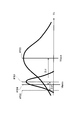
- FIG. 3 illustrates a second method of determining the lower threshold.
- the control unit 113 averages the average of the minimum values of the intercepts Vk of the respective primary approximation straight lines obtained from the input voltage Vc measured a plurality of times by the voltage measurement unit 111 while charging is stopped.
- a value # 301 (Vkmin_ave) is determined, and a value # 302 lower than the determined average value # 301 by a predetermined deviation (for example, 3 ⁇ ) is set as the lower limit threshold Vkmin.
- Vkave is an average value of the intercept Vk of the first-order approximate straight line obtained from the input voltage Vc measured a plurality of times by the voltage measurement unit 111.
- the lower limit threshold value Vkmin is set to a value lower than the average value # 301 of a plurality of minimum values of the intercept Vk of the linear approximation straight line by a predetermined deviation, so that the reliability of the lower limit threshold value Vkmin can be improved. it can.
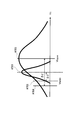
- FIG. 4 is a diagram illustrating a third method of determining the lower threshold.
- the control unit 113 sets a value # 402 lower by a predetermined deviation (for example, 3 ⁇ ) than the average value # 401 of the input voltage Vc measured a plurality of times by the voltage measurement unit 111 while charging is stopped.
- the lower threshold Vkmin is set.
- the lower limit threshold Vkmin can be set higher by determining the lower limit threshold Vkmin based on the average value # 401 of the input voltage, so that the input can be input earlier when the input voltage decreases.
- the current can be reduced, and high safety can be ensured.
- FIG. 5 is a diagram illustrating a fourth method of determining the lower limit threshold.
- the control unit 113 obtains the minimum value # 501 of the input voltage Vc measured a plurality of times by the voltage measurement unit 111 while charging is stopped. Furthermore, the control unit 113 obtains a value # 503 lower by a predetermined deviation (for example, 3 ⁇ ) than the average value # 502 of the input voltage measured a plurality of times by the voltage measurement unit 111 while the charging is stopped. The control unit 113 compares the minimum value # 501 with the value # 503, and sets the higher value # 503 as the lower limit threshold Vkmin.
- FIG. 6 is a diagram illustrating a fifth method of determining the lower limit threshold.
- the control unit 113 obtains the minimum value # 601 of the input voltage Vc measured a plurality of times by the voltage measurement unit 111 while charging is stopped. Further, the control unit 113 obtains a value # 603 lower by a predetermined deviation (for example, 3 ⁇ ) than the average value # 602 of the input voltage measured a plurality of times by the voltage measurement unit 111 while the charging is stopped. The control unit 113 compares the minimum value # 601 with the value # 603, and sets the higher minimum value # 601 as the lower limit threshold Vkmin.
- FIG. 7 is a diagram illustrating an example of a sixth method of determining the lower limit threshold.
- FIG. 8 is a diagram illustrating another example of the sixth method of determining the lower limit threshold.
- control unit 113 sets a value lower by a predetermined deviation (for example, 3 ⁇ ) than average value # 701 of the minimum value of input voltage Vc measured a plurality of times by voltage measurement unit 111 while charging is stopped. Ask for 702. Furthermore, the control unit 113 obtains a value # 704 lower by a predetermined deviation (for example, 3 ⁇ ) than the average value # 703 of the input voltage measured a plurality of times by the voltage measurement unit 111 while the charging is stopped.
- a predetermined deviation for example, 3 ⁇
- the control unit 113 compares the value # 702 with the value # 704, and sets the higher value as the lower limit threshold Vkmin. Specifically, in the case of FIG. 7, the value # 704 is set as the lower limit threshold Vkmin, and in the case of FIG. 8, the value # 702 is set as the lower limit threshold Vkmin.
- any one of the lower limit threshold values obtained by any two methods of the first method to the third method described above may be set as the lower limit threshold value Vkmin. Is also possible. By combining a plurality of methods, it is possible to more accurately consider the fluctuation range of the output voltage of the power supply.
- FIG. 9 is a diagram showing a method of obtaining the amount of change of the input voltage measured by the voltage measurement unit 111.
- FIG. 10 is a diagram illustrating a seventh method of determining the lower limit threshold.
- the control unit 113 calculates the change amount ( ⁇ Vk) of the input voltage Vc measured by the voltage measurement unit 111 every predetermined time ( ⁇ t).
- the control unit 113 obtains the total amount of change by averaging the absolute values of the results, and the above-mentioned temporary threshold # 1001 determined by any one of the first to sixth methods described above.
- a lower threshold value Vkmin is set to a value (# 1002) which is higher by the entire amount of change.
- Vkave is an average value of input voltages measured a plurality of times by the voltage measurement unit 111.
- a margin can be provided by the amount of change, and security can be further secured as compared with the first to sixth methods described above.
- FIG. 11 is a flowchart showing a method of controlling the input current of the charger 114 after the start of charging.
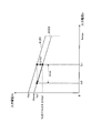
- FIG. 12 is a diagram showing control for reducing the input current of the charger 114 after the start of charging.
- FIG. 13 is a diagram showing control for increasing the input current of the charger 114 after the start of charging.
- Vc1 is an input voltage before reduction
- Vc2 is a reduced input voltage
- Ic1 is an input current before reduction
- Ic2 is an input current after reduction.
- ⁇ Vcr is a voltage drop due to the increase of the load current Id flowing to the electric device 103.
- ⁇ Icr is a current that is reduced by the control of the control unit 113.
- Vkr is the value of the input voltage Vc at the intersection of the first-order approximate straight line # 1201 and the vertical axis.
- Vc3 is an input voltage before rising
- Vc4 is an input voltage after rising
- Ic3 is an input current after rising
- Ic4 is an input current before rising.
- ⁇ Vcs is a voltage increase due to the decrease of the load current Id flowing to the electric device 103.
- ⁇ Ics is a current that is increased by the control of the control unit 113.
- Vks is the value of the input voltage Vc at the intersection of the control straight line # 1301 and the vertical axis.
- control unit 113 controls the input current of charger 114 using first-order approximate straight line # 1201 obtained in advance. The method of determining the first-order approximate straight line # 1201 will be described later.
- control unit 113 determines the lower limit threshold Vkmin according to the method described above (step ST1101).
- control unit 113 obtains the measurement value of the input voltage Vc from the voltage measurement unit 111, and obtains the measurement value of the input current Ic from the current measurement unit 112.
- Control unit 113 determines whether or not charging is required (step ST1102). For example, the control unit 113 determines that charging is unnecessary when the storage battery 115 is in a fully charged state, and determines that charging is necessary when the storage battery 115 is not in a fully charged state.
- step ST1102 NO
- the control unit 113 ends the process.
- step ST1102 determines whether the obtained measured value of the input voltage and the measured value of the input current are on the first approximation straight line # 1201. Is determined (step ST1103).
- step ST 1103 YES
- the current flowing through the power supply circuit does not become an overcurrent even if the input current of the charger 114 is not adjusted.
- the controller 113 continues charging with the input current as it is.
- step ST1104 NO
- the control unit 113 follows the control straight line # 1202 to input current Icr.
- the charger 114 is controlled so as to reduce (step ST1105).
- the charger 114 is controlled to reduce the input current from Ic1 so as to be a voltage.
- the range of the input voltage Vc substantially the same as the input voltage Vc1 is not less than the input voltage Vc1 and a value larger than the input voltage Vc1 by a predetermined amount ⁇ ( ⁇ > 0) or less (Vc1 ⁇ Vc ⁇ (Vc1 + ⁇ )) It is. That is, the concept includes reducing the input current from Ic1 until the input current becomes a voltage higher by a predetermined amount ⁇ than the input voltage Vc1 before reduction.
- step ST1104 when the input voltage Vc is equal to or higher than the lower limit threshold Vkmin (when the voltage-dropped input voltage is equal to or higher than the control straight line # 1202) (step ST1104: YES), the controller 113 increases the input current Ic. The charger 114 is controlled (step ST1106).
- control unit 113 controls the charger 114 to raise the input current from Ic4 so that the obtained control straight line # 1301 has substantially the same input voltage as the input voltage Vc3 before rising. However, at this time, the control unit 113 performs control so as not to exceed the maximum allowable current value Icmax.
- the range of the input voltage Vc substantially the same as the input voltage Vc3 is not less than the input voltage Vc3 and a value smaller than the input voltage Vc3 by a predetermined amount ⁇ (where ⁇ > 0) or more (Vc3 ⁇ Vc ⁇ (Vc3- ⁇ ) )). That is, the concept includes raising the input current from Ic4 until the input current becomes a voltage lower by a predetermined amount ⁇ than the input voltage Vc3 before rising.
- step ST 1102 may be performed to determine whether charging is necessary, and the process of step ST 1101 for determining the lower limit threshold may be performed after it is determined that charging is necessary. .
- the voltage drop ⁇ Vc to the control straight line # 1202 due to the start of the operation of the electric device 103 can be obtained by the equation (2).
- ⁇ Vc ⁇ ZP * ⁇ Id (2)
- Id is the current flowing through the electric device 103
- ZP is the output impedance of the power supply 101.
- the control unit 113 reduces the input current Ic to compensate for the influence of the voltage drop ⁇ Vc obtained from the equation (2).
- Vc Vp-ZP (Ic + Id)-ZL * Ic (3)
- Vp is the voltage Ic of the power source 101
- the output impedance ZL of the power source 101 is Impedance of the wiring between the power supply 101 and the charger 114
- Vc (Vp-ZP * Id) -ZS * Ic (4)
- Zs is the combined impedance of ZP and ZL
- Vk Vp-ZP * Id (5)
- Vp the voltage of the power supply 101
- Id the current flowing through the electric device 103
- ZP the output impedance of the power supply 101
- Vc1 Vk-ZS * Ic1 (6)
- Vc2 Vk-ZS * Ic2 (7)
- equation (10) is obtained by substituting equation (1) into equation (9).
- ⁇ Id ⁇ (ZS / ZP) * ⁇ Ic (10)
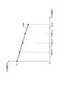
- FIG. 14 is a diagram showing the relationship between the input voltage and the input current in the method of obtaining the relationship between the input voltage and the input current as the first-order approximate straight line # 1201.
- the control unit 113 obtains, for example, a linear approximate straight line # 1201 before the start of charging.
- the control unit 113 sequentially changes the input current Ic at predetermined time intervals, and acquires the measured value of the input voltage Vc at each timing. For example, as shown in FIG. 14, the control unit 113 sequentially changes the input current Ic in the order of “0”, “1/4 Icmax”, “2/4 Icmax”, “3/4 Icmax”, and “Icmax”. To obtain the measured value of the input voltage Vc. Then, the acquired input current Ic and the input voltage Vc are associated with each other and stored as a table.
- the control unit 113 obtains the relationship between the value of each input current Ic changed and the measured value of each input voltage Vc with respect to each input current Ic as a first-order approximate straight line # 1201.
- the first-order approximate straight line # 1201 is obtained by, for example, the least squares method.
- the method of obtaining the first-order approximate straight line # 1201 is not limited to the least square method, and methods other than the least square method can be used.
- the present embodiment when the voltage drop of the input voltage occurs due to the use of another electric device during charging, only the input current for compensating the influence of the voltage drop to the lower limit threshold is reduced. Therefore, it can be charged at the maximum input current that can be used for charging.
- control is performed to reduce the input current of the charger 114 in one step.
- control may be performed so as to reduce in multiple steps.
- calculation of Vkmin, Vkave, deviation 3 ⁇ , etc. is performed while charging is stopped, but the present invention is not limited to this, and even after charging is started (during charging), Vkmin, The calculation of Vkave, deviation 3 ⁇ , etc. may be performed. By doing this, it is possible to perform control in consideration of the fluctuation of the output voltage of the power supply during charging.
- a first-order approximation straight line is obtained before the start of charging, and the input current of the charger is controlled according to the first-order approximation straight line after the start of charging.
- the first approximation line may be obtained at timing.
- the control unit 113 shuts off the power supply circuit 180 at the breaker board 106 and shuts off the supply of power from the power supply 101 to the storage battery 115.
- the maximum Ic it is possible to store the maximum Ic at the time of interruption.
- control unit 113 when charging storage battery 115, control unit 113 does not exceed maximum allowable current value Icmax as the maximum Ic stored when obtaining the first approximation line. Can adjust the input current Ic.
- the on-vehicle charging device is suitable, for example, for charging a storage battery, which is a power source of a vehicle such as an electric vehicle, using a home power supply.
Landscapes
- Engineering & Computer Science (AREA)
- Power Engineering (AREA)
- Transportation (AREA)
- Mechanical Engineering (AREA)
- Manufacturing & Machinery (AREA)
- Chemical & Material Sciences (AREA)
- Chemical Kinetics & Catalysis (AREA)
- Electrochemistry (AREA)
- General Chemical & Material Sciences (AREA)
- Charge And Discharge Circuits For Batteries Or The Like (AREA)
- Electric Propulsion And Braking For Vehicles (AREA)
Abstract
Description
<充電システムの構成>
図1は、本発明の実施の形態に係る充電システム100の構成を示す図である。
車載用充電装置170は、電圧測定部111と、電流測定部112と、制御部113と、充電器114とを有する。
下限閾値Vkminは、ブレーカ盤106のA点の電圧Vkの下限とする値であり、蓄電池115の充電開始後において電気機器103の使用を開始した際に、電源供給回路180に過電流が流れないように入力電流を制御するために、一次近似直線と共に用いられるパラメータである。入力電圧Vcが下限閾値以下になった場合に入力電流Icを低下させる制御が、また入力電圧Vcが下限閾値以上である場合に入力電流Icを増加させる制御が、それぞれ行われる。この電流制御と一次近似直線との関係については、後述する。
Vc=Vk-Zs*Ic (1)
ただし、Vcは、充電器114の入力電圧
Vkは、一次近似直線の切片
Zsは、電源101の出力インピーダンスと、電源101と充電器114との間の配線のインピーダンスとの合成インピーダンス
Icは、充電器114の入力電流
図2は、下限閾値を決定する第1の方法を示す図である。
図3は、下限閾値を決定する第2の方法を示す図である。
図4は、下限閾値を決定する第3の方法を示す図である。
図5は、下限閾値を決定する第4の方法を示す図である。
図6は、下限閾値を決定する第5の方法を示す図である。
図7は、下限閾値を決定する第6の方法の一例を示す図である。図8は、下限閾値を決定する第6の方法の他の一例を示す図である。
図9は、電圧測定部111で測定した入力電圧の変化量を求める方法を示す図である。図10は、下限閾値を決定する第7の方法を示す図である。
車載用充電装置170の充電中に、家屋150側の電気機器103の電力使用量が増加し、充電器114への入力電圧が低下した場合の制御は、以下のように行われる。
電気機器103が停止している状態において、車載用充電装置170が電源101を用いて蓄電池115の充電を開始した後に、電気機器103が電源101から電源の供給を受けて動作を開始する場合を例に、図12を用いて説明する。
ΔVc=-ZP*ΔId (2)
ただし、Idは、電気機器103に流れる電流
ZPは、電源101の出力インピーダンス
Vc=Vp-ZP(Ic+Id)-ZL*Ic (3)
ただし、Vpは、電源101の電圧
Icは、ブレーカ盤106のA点(図1参照)から充電器114に流れる電流
Idは、電気機器103に流れる電流
ZPは、電源101の出力インピーダンス
ZLは、電源101と充電器114との間の配線のインピーダンス
Vc=(Vp-ZP*Id)-ZS*Ic (4)
ただし、Zsは、ZPとZLとの合成インピーダンス
Vk=Vp-ZP*Id (5)
ただし、Vpは、電源101の電圧
Idは、電気機器103に流れる電流
ZPは、電源101の出力インピーダンス
Vc1=Vk-ZS*Ic1 (6)
Vc2=Vk-ZS*Ic2 (7)
ΔVc=-ZS*ΔIc (8)
ΔIc=-ΔVc/ZS (9)
ΔId=-(ZS/ZP)*ΔIc (10)
図14は、入力電圧と入力電流との関係を一次近似直線#1201として求める方法における入力電圧と入力電流との関係を示す図である。
このように、本実施の形態によれば、電源の出力電圧の変動幅を考慮して車載用充電器の入力電流を制御することにより、不安定な電源を用いて充電する場合であっても、充電できなくなることを防ぐことができるとともに、家屋等で他の電気機器の使用ができない状態を防ぐことができる。
上記の実施の形態において、充電器114の入力電流を一段階で低減する制御を行ったが、本発明はこれに限らず、複数段階に分けて低減するように制御してもよい。
101 電源
102 出力インピーダンス
103 電気機器
104 インピーダンス
105 ソケット
106 ブレーカ盤
111 電圧測定部
112 電流測定部
113 制御部
114 充電器
115 蓄電池
150 家屋
160 車両
170 車載用充電装置
180 電源供給回路
Claims (10)
- 車両の外部にある電源から前記車両に搭載された蓄電池を充電する車載用充電装置であって、
前記外部にある電源と接続し、前記蓄電池を充電するための入力電流が可変である充電器と、
前記充電器の入力電流と前記入力電流に対応する入力電圧とを測定する測定部と、
前記充電器の入力電流を複数の値に変化させ、それぞれ変化させた際の前記入力電流と前記測定部により測定した前記入力電圧との対応関係に従って、前記入力電流および前記入力電圧の適正範囲の下限閾値を決定するとともに、充電開始後に、前記対応関係及び前記下限閾値に従って、前記入力電圧が変化した際に前記入力電流を制御する制御部と、
を具備する車載用充電装置。 - 前記制御部は、前記対応関係を一次近似直線として求めるとともに前記下限閾値を前記一次近似直線の切片に基づいて決定し、前記一次近似直線及び前記下限閾値に従って、前記入力電圧が変化した際に前記入力電流を制御する、
請求項1記載の車載用充電装置。 - 前記制御部は、充電開始後に前記入力電圧が前記一次近似直線と同一の傾きでかつ前記下限閾値を通る制御用直線を求め、前記制御用直線上において低下前の前記入力電圧と略同一の入力電圧となる入力電流まで前記入力電流を低下させる制御を行い、充電開始後に前記入力電圧が上昇した場合には、前記一次近似直線と同一の傾きでかつ上昇前の前記入力電圧と略同一の入力電圧となる入力電流まで前記入力電流を上昇させる制御を行う、
請求項2記載の車載用充電装置。 - 前記制御部は、複数回に渡って測定した前記一次近似直線の切片の測定時点までの最小値を前記下限閾値とする、
請求項2記載の車載用充電装置。 - 前記制御部は、所定回数に渡って測定した前記一次近似直線の切片の最小値を前記所定回数毎に求め、求めた各々の前記最小値の平均値を求めるとともに、前記平均値よりも所定の偏差だけ小さい値を前記下限閾値とする、
請求項2記載の車載用充電装置。 - 前記制御部は、複数回に渡って測定した前記一次近似直線の切片の平均値よりも所定の偏差だけ小さい値を前記下限閾値とする、
請求項2記載の車載用充電装置。 - 前記制御部は、複数回に渡って測定した前記一次近似直線の切片の変化量を求めるとともに、前記変化量の平均値を暫定閾値とし、前記下限閾値より前記暫定閾値だけ大きい値を新たな前記下限閾値とする、
請求項2記載の車載用充電装置。 - 前記制御部は、
複数回に渡って測定した前記一次近似直線の切片の測定時点までの最小値、
所定回数に渡って測定した前記一次近似直線の切片の最小値を前記所定回数毎に求め、求めた各々の前記最小値の平均値を求めるとともに、前記平均値よりも所定の偏差だけ小さい値、
および複数回に渡って測定した前記一次近似直線の切片の平均値よりも所定の偏差だけ小さい値、
の少なくとも2つの値を算出し、前記2つの値のうちいずれか大きい方の値を前記下限閾値とする、
請求項2記載の車載用充電装置。 - 前記制御部は、前記対応関係を求める過程において前記外部にある電源からの前記蓄電池に対する電源の供給が遮断された場合には、次回に前記対応関係を求める際には、前記遮断の前に設定した入力電流のうちの最大値以下の入力電流により前記対応関係を求める
請求項1記載の車載用充電装置。 - 前記制御部は、充電開始前、および、充電開始後の少なくとも一方において、前記対応関係に従って前記下限閾値を決定する、
請求項1記載の車載用充電装置。
Priority Applications (2)
| Application Number | Priority Date | Filing Date | Title |
|---|---|---|---|
| US14/008,225 US20140015486A1 (en) | 2011-03-30 | 2012-03-29 | Vehicle charging device |
| JP2013507201A JP5942171B2 (ja) | 2011-03-30 | 2012-03-29 | 車載用充電装置 |
Applications Claiming Priority (2)
| Application Number | Priority Date | Filing Date | Title |
|---|---|---|---|
| JP2011076124 | 2011-03-30 | ||
| JP2011-076124 | 2011-03-30 |
Publications (1)
| Publication Number | Publication Date |
|---|---|
| WO2012132459A1 true WO2012132459A1 (ja) | 2012-10-04 |
Family
ID=46930229
Family Applications (1)
| Application Number | Title | Priority Date | Filing Date |
|---|---|---|---|
| PCT/JP2012/002197 Ceased WO2012132459A1 (ja) | 2011-03-30 | 2012-03-29 | 車載用充電装置 |
Country Status (3)
| Country | Link |
|---|---|
| US (1) | US20140015486A1 (ja) |
| JP (1) | JP5942171B2 (ja) |
| WO (1) | WO2012132459A1 (ja) |
Cited By (2)
| Publication number | Priority date | Publication date | Assignee | Title |
|---|---|---|---|---|
| WO2015007236A1 (en) | 2013-07-18 | 2015-01-22 | Mediatek Inc. | Method, charger device, and adaptor capable of maximum output power point tracking |
| AU2014306867B2 (en) * | 2013-08-12 | 2017-10-26 | Genentech, Inc. | Compositions and method for treating complement-associated conditions |
Families Citing this family (4)
| Publication number | Priority date | Publication date | Assignee | Title |
|---|---|---|---|---|
| US10661501B2 (en) | 2014-06-20 | 2020-05-26 | Carbon, Inc. | Three-dimensional printing method using increased light intensity and apparatus therefor |
| KR20170017941A (ko) | 2014-06-20 | 2017-02-15 | 카본, 인크. | 중합성 액체의 왕복 공급을 통한 3차원 프린팅 |
| US11390062B2 (en) | 2014-08-12 | 2022-07-19 | Carbon, Inc. | Three-dimensional printing with supported build plates |
| JP7544083B2 (ja) * | 2022-02-08 | 2024-09-03 | トヨタ自動車株式会社 | 車両 |
Citations (3)
| Publication number | Priority date | Publication date | Assignee | Title |
|---|---|---|---|---|
| JPH05137276A (ja) * | 1991-11-12 | 1993-06-01 | Oki Electric Ind Co Ltd | 電子機器用充電装置 |
| JP2003092829A (ja) * | 2001-09-18 | 2003-03-28 | Hitachi Ltd | 電気機器システム |
| JP2012039685A (ja) * | 2010-08-04 | 2012-02-23 | Hitachi Ltd | 蓄電池制御装置,充電スタンド及び蓄電池制御方法 |
Family Cites Families (5)
| Publication number | Priority date | Publication date | Assignee | Title |
|---|---|---|---|---|
| US7486056B2 (en) * | 2006-11-15 | 2009-02-03 | Elster Electricity, Llc | Input current or voltage limited power supply |
| US8736224B2 (en) * | 2007-03-09 | 2014-05-27 | Ford Global Technologies, Llc | Charging a battery using a circuit having shared loads |
| WO2010137144A1 (ja) * | 2009-05-28 | 2010-12-02 | トヨタ自動車株式会社 | 充電システム |
| US20120153895A1 (en) * | 2010-12-20 | 2012-06-21 | Ford Global Technologies, Llc | System And Method For Controlling AC Line Current And Power During Vehicle Battery Charging |
| CN103392133A (zh) * | 2011-03-07 | 2013-11-13 | 株式会社日立制作所 | 电池状态推定方法和电池管理系统 |
-
2012
- 2012-03-29 US US14/008,225 patent/US20140015486A1/en not_active Abandoned
- 2012-03-29 WO PCT/JP2012/002197 patent/WO2012132459A1/ja not_active Ceased
- 2012-03-29 JP JP2013507201A patent/JP5942171B2/ja not_active Expired - Fee Related
Patent Citations (3)
| Publication number | Priority date | Publication date | Assignee | Title |
|---|---|---|---|---|
| JPH05137276A (ja) * | 1991-11-12 | 1993-06-01 | Oki Electric Ind Co Ltd | 電子機器用充電装置 |
| JP2003092829A (ja) * | 2001-09-18 | 2003-03-28 | Hitachi Ltd | 電気機器システム |
| JP2012039685A (ja) * | 2010-08-04 | 2012-02-23 | Hitachi Ltd | 蓄電池制御装置,充電スタンド及び蓄電池制御方法 |
Cited By (3)
| Publication number | Priority date | Publication date | Assignee | Title |
|---|---|---|---|---|
| WO2015007236A1 (en) | 2013-07-18 | 2015-01-22 | Mediatek Inc. | Method, charger device, and adaptor capable of maximum output power point tracking |
| EP3022826A4 (en) * | 2013-07-18 | 2016-12-21 | Mediatek Inc | METHOD, LOADING DEVICE DEVICE AND ADAPTER FOR MPP TRACKING |
| AU2014306867B2 (en) * | 2013-08-12 | 2017-10-26 | Genentech, Inc. | Compositions and method for treating complement-associated conditions |
Also Published As
| Publication number | Publication date |
|---|---|
| US20140015486A1 (en) | 2014-01-16 |
| JP5942171B2 (ja) | 2016-06-29 |
| JPWO2012132459A1 (ja) | 2014-07-24 |
Similar Documents
| Publication | Publication Date | Title |
|---|---|---|
| JP5455705B2 (ja) | 充電装置と充電方法 | |
| JP5682433B2 (ja) | 充電制御システム | |
| US9876353B2 (en) | Method and apparatus for transmitting electrical power | |
| WO2019155751A1 (ja) | 車載充電装置、及び車載充電装置の制御方法 | |
| JP5942171B2 (ja) | 車載用充電装置 | |
| CN112106288B (zh) | 电力变换装置以及电力变换系统 | |
| CN105277909B (zh) | 混合动力功率电池soc校准方法 | |
| US10355320B2 (en) | Power storage device for a battery group and connection control of capacitor and switching device | |
| KR101871020B1 (ko) | 태양광 인버터를 이용한 에너지 저장 장치의 배터리 충전 시스템 | |
| JP2015186316A (ja) | 二次電池の充電システム及び方法並びに電池パック | |
| WO2015162877A1 (ja) | リチウムイオン二次電池システム及びリチウム二次電池システムの運転方法 | |
| JP5657602B2 (ja) | 車載用充電装置 | |
| CN103597705B (zh) | 电动车辆用充电装置和电动车辆用充电系统 | |
| JP7071229B2 (ja) | 電源システム | |
| EP4266524A1 (en) | Droop control in a dc operated system | |
| US20150115872A1 (en) | Power Converter | |
| JP5919517B2 (ja) | 車載用充電装置 | |
| KR101927670B1 (ko) | 충전 모드 자동 변경 무선 충전 장치 및 방법 | |
| JP6256976B2 (ja) | 電動車に接続して使用される電力変換装置 | |
| JP2019106771A (ja) | 車載充電システム | |
| JP6433314B2 (ja) | 充電装置 | |
| JP2023110252A (ja) | 電力供給設備 | |
| KR101846683B1 (ko) | 전기차량의 충전시스템 및 충전 제어방법 | |
| JP2022122617A (ja) | 充放電要素の充放電制御方法、及び充放電要素の充放電制御装置 | |
| JP2015192585A (ja) | 電動車両の充電装置及び方法 |
Legal Events
| Date | Code | Title | Description |
|---|---|---|---|
| 121 | Ep: the epo has been informed by wipo that ep was designated in this application |
Ref document number: 12764558 Country of ref document: EP Kind code of ref document: A1 |
|
| ENP | Entry into the national phase |
Ref document number: 2013507201 Country of ref document: JP Kind code of ref document: A |
|
| WWE | Wipo information: entry into national phase |
Ref document number: 14008225 Country of ref document: US |
|
| NENP | Non-entry into the national phase |
Ref country code: DE |
|
| 122 | Ep: pct application non-entry in european phase |
Ref document number: 12764558 Country of ref document: EP Kind code of ref document: A1 |