WO2012132476A1 - Grille pour batterie au plomb, plaque positive utilisant une grille, groupe de plaques, batterie au plomb, et procédé de fabrication de plaque positive pour batterie au plomb - Google Patents
Grille pour batterie au plomb, plaque positive utilisant une grille, groupe de plaques, batterie au plomb, et procédé de fabrication de plaque positive pour batterie au plomb Download PDFInfo
- Publication number
- WO2012132476A1 WO2012132476A1 PCT/JP2012/002286 JP2012002286W WO2012132476A1 WO 2012132476 A1 WO2012132476 A1 WO 2012132476A1 JP 2012002286 W JP2012002286 W JP 2012002286W WO 2012132476 A1 WO2012132476 A1 WO 2012132476A1
- Authority
- WO
- WIPO (PCT)
- Prior art keywords
- lead
- grid
- electrode plate
- lattice
- positive electrode
- Prior art date
- Legal status (The legal status is an assumption and is not a legal conclusion. Google has not performed a legal analysis and makes no representation as to the accuracy of the status listed.)
- Ceased
Links
Images

Classifications
-
- H—ELECTRICITY
- H01—ELECTRIC ELEMENTS
- H01M—PROCESSES OR MEANS, e.g. BATTERIES, FOR THE DIRECT CONVERSION OF CHEMICAL ENERGY INTO ELECTRICAL ENERGY
- H01M4/00—Electrodes
- H01M4/02—Electrodes composed of, or comprising, active material
- H01M4/64—Carriers or collectors
- H01M4/70—Carriers or collectors characterised by shape or form
- H01M4/72—Grids
- H01M4/73—Grids for lead-acid accumulators, e.g. frame plates
-
- H—ELECTRICITY
- H01—ELECTRIC ELEMENTS
- H01M—PROCESSES OR MEANS, e.g. BATTERIES, FOR THE DIRECT CONVERSION OF CHEMICAL ENERGY INTO ELECTRICAL ENERGY
- H01M4/00—Electrodes
- H01M4/02—Electrodes composed of, or comprising, active material
- H01M4/64—Carriers or collectors
- H01M4/70—Carriers or collectors characterised by shape or form
- H01M4/72—Grids
- H01M4/74—Meshes or woven material; Expanded metal
- H01M4/745—Expanded metal
-
- H—ELECTRICITY
- H01—ELECTRIC ELEMENTS
- H01M—PROCESSES OR MEANS, e.g. BATTERIES, FOR THE DIRECT CONVERSION OF CHEMICAL ENERGY INTO ELECTRICAL ENERGY
- H01M2220/00—Batteries for particular applications
- H01M2220/20—Batteries in motive systems, e.g. vehicle, ship, plane
-
- Y—GENERAL TAGGING OF NEW TECHNOLOGICAL DEVELOPMENTS; GENERAL TAGGING OF CROSS-SECTIONAL TECHNOLOGIES SPANNING OVER SEVERAL SECTIONS OF THE IPC; TECHNICAL SUBJECTS COVERED BY FORMER USPC CROSS-REFERENCE ART COLLECTIONS [XRACs] AND DIGESTS
- Y02—TECHNOLOGIES OR APPLICATIONS FOR MITIGATION OR ADAPTATION AGAINST CLIMATE CHANGE
- Y02E—REDUCTION OF GREENHOUSE GAS [GHG] EMISSIONS, RELATED TO ENERGY GENERATION, TRANSMISSION OR DISTRIBUTION
- Y02E60/00—Enabling technologies; Technologies with a potential or indirect contribution to GHG emissions mitigation
- Y02E60/10—Energy storage using batteries
-
- Y—GENERAL TAGGING OF NEW TECHNOLOGICAL DEVELOPMENTS; GENERAL TAGGING OF CROSS-SECTIONAL TECHNOLOGIES SPANNING OVER SEVERAL SECTIONS OF THE IPC; TECHNICAL SUBJECTS COVERED BY FORMER USPC CROSS-REFERENCE ART COLLECTIONS [XRACs] AND DIGESTS
- Y02—TECHNOLOGIES OR APPLICATIONS FOR MITIGATION OR ADAPTATION AGAINST CLIMATE CHANGE
- Y02P—CLIMATE CHANGE MITIGATION TECHNOLOGIES IN THE PRODUCTION OR PROCESSING OF GOODS
- Y02P70/00—Climate change mitigation technologies in the production process for final industrial or consumer products
- Y02P70/50—Manufacturing or production processes characterised by the final manufactured product
Definitions
- the present invention relates to a lead-acid battery grid, a positive electrode plate using the grid, an electrode plate group, a lead-acid battery, and a method for producing a lead-acid battery positive electrode plate.
- Lead-acid batteries have advantages such as low cost, stable output, and applicability to large-current discharge, and have been widely used in fields such as vehicle start-up, main power sources for electric vehicles or electric tools, and backup power sources.
- the lead acid battery mainly includes an open type liquid lead acid battery and a sealed valve control type lead acid battery.
- Valve controlled lead-acid batteries have the advantage of being maintenance-free and are therefore more widely used.
- the valve-controlled lead-acid battery is composed of a positive electrode plate, a negative electrode plate, a separator, an electrolyte, a casing with a safety valve, and the like.
- the positive electrode plate and the negative electrode plate are formed by filling an active material into an alloy lattice.
- Lead-acid battery grids are mainly divided into two types: cast grids made by casting and expanded grids made by expanding.
- the expanded lattice produced by the expanding process can not only reduce the material cost but also reduce the variation in weight as compared with the cast lattice produced by the casting process, and the productivity can be greatly improved.
- Rotational (rotary) expanding methods and reciprocating (reciprocating) expanding methods are well known as methods for producing expanded lattices.
- a metal sheet has a disk-shaped cutter and is carried in between a pair of rotating rollers to perform an expanding process. Since the lattice is subjected to high stress twice in the slit formation and stretching processes, the lattice lines at the node are easily broken, which adversely affects the life of the battery.
- a metal sheet is intermittently carried into a mold having a pair of cutters, and slits arranged intermittently in the width direction are formed in the metal sheet by the reciprocating movement of the cutter. While forming one row at a time, the slits are pulled vertically downward by a cutter to form a mesh.
- the grid line is not twisted regardless of the pressure at the nodes of the lattice, and therefore, a lead-acid battery manufactured using such an expanded lattice exhibits excellent life characteristics.
- the reciprocating expand method has a drawback that the production speed is low.
- a plurality of plate-like cutters are overlapped so as to be V-shaped at a predetermined interval, whereby a diagonal slit is formed in the length direction by one punching.
- a method capable of forming a plurality of rows is disclosed. By this method, a rolled grid sheet having a fine mesh can be produced with high production efficiency.
- a lead-acid battery used for an electric bicycle or the like that needs to be repeatedly subjected to deep discharge may require high-rate discharge even when the charge depth (SOC) is shallow. Under such use conditions, overdischarge tends to occur. In order to suppress a rapid drop in the positive electrode voltage during overdischarge, it is necessary to reduce the current collecting property of the positive electrode.
- the outer frame does not exist at the edge of the expanded grid, the current collecting property is lower than that of the cast grid.
- the active material tends to overflow from the edge of the lattice, the carrying amount is limited. Therefore, when an expanded lattice is used for both the positive electrode plate and the negative electrode plate of the lead storage battery, the battery capacity is low, the active material overflows, and an internal short circuit may occur.
- Patent Document 2 discloses that the voltage drop during high-rate discharge can be improved by using an expanded grid for the positive electrode plate and a cast grid for the negative electrode plate.
- Patent Document 3 discloses using an expanded lattice for the positive electrode and a cast lattice for the negative electrode in order to prevent the active material from overflowing from the positive electrode lattice and causing an internal short circuit.
- the alloy lattice mainly has a function of supporting an active material and a current collecting function. If the adhesiveness between the lattice and the active material is insufficient, the active material is easily peeled off during the charge / discharge process. In addition, non-uniformity of current collection occurs inside the active material, and the active material far from the lattice is likely to deteriorate during overdischarge.
- Patent Documents 4 to 7 the grid line width, grid line thickness, node cross section, grid thickness, mesh shape, and the like are optimized and designed. It is disclosed to avoid the corrosion and breakage of the wire, improve the adhesiveness of the active material, and improve the battery life characteristics. However, the cycle characteristics under high-rate discharge conditions are insufficient.
- the main object of the present invention is to provide a lead-acid battery having an excellent cycle life even when high-rate discharge is repeated under a shallow depth of charge (SOC).
- the lead-acid battery grid according to the present invention is a lead-acid battery grid composed of an expanded grid formed by a reciprocating method, where the width of the grid line of the expanded grid is W and the thickness of the expanded grid is T. / W is in the range of 1.5 to 1.9.
- W / t is preferably in the range of 1.25 to 1.60, where t is the thickness of the expanded lattice.
- P / T is in the range of 1.1 to 1.4, where P is the thickness of the positive electrode plate. It is preferable that it exists in.
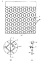
- (A) is the front view which showed typically the expanded lattice in one Embodiment of this invention
- (b) is the figure which expanded a part of expanded lattice of (a)
- (c) is 2B is a cross-sectional view taken along line AA in FIG.
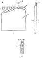
- (A) is the front view which showed typically the positive electrode plate in one Embodiment of this invention
- (b) is a side view of a positive electrode plate
- (c) is the thickness direction of a positive electrode plate. It is a fragmentary sectional view when cut along. It is a partially cutaway perspective view of a lead acid battery in one embodiment of the present invention. It is the table
- both the positive electrode plate and the negative electrode plate can have a slightly longer battery life than the case where an expanded lattice or a cast lattice is used, but cannot reach a desired level.
- the inventor of the present application pays attention to the design improvement of the positive electrode grid, and as a result of repeated studies for improving the adhesion between the active material and the grid, improving the high rate discharge characteristics of the battery, etc., the following knowledge was obtained. .
- a shaping process is generally performed on a lattice-shaped sheet formed by an expanding process in order to easily perform a subsequent application process.
- the grid sheet is pressed into a sheet shape thinner than the original lead sheet, thereby reducing the thickness of the grid and corroding near the node of the positive plate grid.
- interval of the slit in an expanding process is made small, the width
- Patent Document 6 and Patent Document 7 disclose that the interval between the slits is controlled to be equal to or less than the thickness of the lead sheet in order to reduce the weight of the lattice.
- the present inventor has discovered the following.
- the grid-like sheet obtained by the expanding process if the grid-like sheet is not pressed thinly and the bending degree of the expanded grid after shaping is controlled within a suitable range, an excellent lead paste Application property is obtained.
- the lead paste is not easily deteriorated even when high rate discharge is repeatedly performed at a shallow depth of charge, and excellent high rate discharge cycle characteristics are obtained.
- the present invention is a lead-acid battery grid composed of an expanded grid formed by a reciprocating system, where the width of the expanded grid line is W and the thickness of the expanded grid is T, T / W is in the range of 1.5 to 1.9. T / W is a ratio representing the degree of bending of the lattice.
- the ratio W / t of the width W of the lattice line to the thickness t of the lattice line is preferably in the range of 1.25 to 1.60.
- the thickness of the positive electrode plate is P
- the thickness P of the positive electrode plate and the thickness T of the positive electrode plate is preferably in the range of 1.1 to 1.4.
- the grid of the negative electrode plate is formed by a casting method. It preferably consists of a cast grid formed.
- the manufacturing method of the positive electrode plate for lead acid batteries in the present invention is as follows.
- step (1) the width direction of the lead sheet is such that T / W is in the range of 1.5 to 1.9, where W is the width of the expanded lattice line and T is the thickness of the expanded lattice.
- step (2) the pitch between the pair of rollers and the roller pressure are adjusted.
- the W / t is in the range of 1.25 to 1.60 according to the thickness of the lead sheet.
- the interval of the slits in the width direction of the lead sheet is adjusted.
- the coating amount of the lead paste is adjusted in step (3) so that P / T is in the range of 1.1 to 1.4.
- the action of the lattice in the electrode plate is the support of the active material and the transmission of current between the active material and the terminal.
- the grid is usually designed in a rectangular shape and has ears for connection to the bus bar.
- the cast grid produced by the casting method has outer and inner and vertical grid lines, while the expanded grid produced by the expand method is formed by forming a slit on a lead sheet using a press die and then pulling it. This is a formed mesh sheet.
- the expanded grid is lighter in weight and superior in uniformity, so that the productivity is higher.
- the lattice of the present invention is an expanded lattice obtained by expanding a lead sheet by the reciprocating expanding method.
- a lead sheet for example, a Pb alloy foil containing at least one of Ca and Sn can be used. In consideration of corrosion resistance and mechanical strength, it is preferable to use a Pb—Ca—Sn ternary alloy.
- a reciprocating press mold having a pair of movable mold and fixed mold.
- the movable mold (upper mold) has a plurality of continuous cutter parts, and these cutter parts are arranged in a V shape in the lead sheet conveyance direction (that is, the length direction).
- a cutter portion is not provided at a position corresponding to the central portion in the vertical direction.
- the fixed mold (lower mold) has a plurality of continuous rib portions, and the rib-like surfaces of the rib portions are provided at positions corresponding to the upper cutter portion.
- ⁇ Fix the fixed mold and press the lead sheet from the top to the bottom of the movable mold.
- the cutter part of the movable mold passes through the rib line between adjacent rib parts, it forms multiple intermittent slits on the lead sheet, and the tip of the cutter part continues to press downward, along the rib-shaped surface
- the slit is widened in a direction perpendicular to the lead sheet surface.
- the lead sheet is processed into a lattice-like sheet having a plurality of meshes by repeating the press while conveying the lead sheet along the length direction of the lead sheet.
- the central part in the width direction of the lead sheet becomes a plain part without a mesh, and the part is formed by the cutting frame described later and the upper frame of the grid and the electrode plate. It becomes the ear.
- the pitch between the pair of rollers and the roller pressure are controlled, and a small pressure is applied to the node portion, thereby increasing the height of the node portion.
- the bending degree of the lattice is maintained as it is with little compression.
- the corrosion resistance is excellent, the variation in the size of the lattice is small, and the variation in the thickness of the lattice is also reduced.
- FIGS. 1A to 1C are diagrams schematically showing the expanded lattice 1 of the present invention obtained by the above method.
- the expanded lattice 1 has a substantially rhombic mesh i formed by intersecting a plurality of lattice lines g, and each mesh i is surrounded by four lattice lines g.
- the mesh i is connected by the node f.
- the expanded lattice 1 is a plain portion in which the mesh i is not formed at the center in the width direction.
- FIG. 1A only the lower part from the center of the expanded lattice 1 is shown. Since the other half has a symmetrical shape, the illustration is omitted.
- FIG. 1B After expanding the slits cut out from the lead sheet by expanding, lattice lines g having a certain width and thickness are formed.
- the width W of the grid line g is such that adjacent slits correspond to gaps in the width direction of the lead sheet (slit spacing), and the thickness t of the grid line g is Corresponds to the thickness.
- the plane on which the grid line g is located is shown to coincide with the paper surface. However, in reality, the plane on which the grid line g is located has a certain inclination with respect to the paper surface.
- FIG. 1C is a cross-sectional view taken along the line AA in FIG.
- the grid line g having a width W has a bent zigzag shape.
- the two lattice lines g overlap each other, the length of the overlapping portion is twice the width W of the lattice line g, and the thickness of the overlapping portion ((hatched portion) is the thickness t of the lattice line g.
- the maximum height in the thickness direction of the entire lattice that is, the height in the thickness direction of the node f
- the ratio (T / W) is defined as the degree of bending of the lattice.
- the bending degree (T / W) of the lattice is controlled within the range of 1.5 to 1.9. can do.
- the filling property of the lead paste as the active material is improved in the subsequent filling step.
- the lead paste can be smoothly filled in each mesh of the grid, but also the lead paste can be filled higher than the height of the surface of the grid.
- filling the lead paste higher than the height of the surface of the lattice is called “overfilling” of the lead paste.
- an excellent applicability of lead paste can be obtained by increasing the bending degree (T / W) of the expanded lattice as compared with the conventional one.
- the edge of the expanded lattice is not supported by the outer frame, so in order to avoid the active material from overflowing from the edge of the lattice, the amount of active material to be filled must be limited. If the applied active material layer is too thin, the capacity of the battery is limited, and the current collection of the grid becomes relatively excessive, which tends to cause deterioration of the active material. On the other hand, if the applied active material layer is too thick, the surface of the outer layer of the active material is too far from the lattice, the adhesiveness with the lattice is insufficient, and the current collection is not uniform in the active material. . As a result, the active material is liable to be peeled off at the end of discharge, which causes deterioration of the battery recycling life. Therefore, it is necessary to control the overfilling rate of the lead paste within an appropriate range.
- the bending degree (T / W) of the lattice is preferably in the range of 1.5 to 1.9, more preferably in the range of 1.6 to 1.8, and 1.65. More preferably, it is in the range of ⁇ 1.75.
- the degree of bending of the lattice is too small, the adhesion of the active material on the surface of the lead paste is poor, and peeling is easily caused when repeated deep discharges are performed, thereby shortening the cycle life of the battery.
- the degree of bending of the lattice is too large, excess current collection occurs, the deterioration of the active material during overdischarge proceeds, and the cycle life of the battery is shortened.
- a lattice having a preferred range of bending degree (T / W) can be manufactured using a reciprocating press mold without destroying the lattice node.
- a characteristic of the reciprocating press is that it hardly compresses the nodes of the lattice, so that a lattice-like sheet having a high degree of bending can be produced.
- a shaping mold with a small pressure applied to the node portion of the lattice is adopted. Therefore, the expanded lattice obtained after the shaping has a large degree of bending and the node portion hardly receives pressure. Therefore, high strength is maintained, corrosion becomes difficult, and battery life can be extended.
- the magnitude of the bending degree (T / W) of the grating is determined by two elements, namely, the grating thickness T and the grating line width W.
- the grating thickness T is mainly determined by the grating. Is related to the ratio of the thickness before the rolling of the sheet-like sheet and the thickness before and after the grid-like sheet is rolled in the shaping process.
- the thickness of the grid-like sheet is such as the size of the mesh and the width W of the grid line. Determined by the element. Therefore, a desired bending degree (T / W) can be obtained by appropriately controlling process conditions in the expanding process and the shaping process.
- the size of the mesh to be formed can be controlled by appropriately adjusting the downward stroke size or the slit length of the movable die of the reciprocating press die.
- the interval of the slits on the lead sheet can be adjusted by adjusting the pitch of the rib-shaped surfaces of the fixed mold and the distance between the cutter parts of the movable mold.
- the ratio of the thickness of the grid sheet before and after the grid sheet is rolled can be controlled by adjusting the pitch of the pair of rollers for rolling the grid sheet, the pressing force of the rollers, and the like.
- the thickness of the lead sheet to be used that is, the thickness t of the lattice line g
- the thickness W of the lattice line g there is a certain preferable range for the slit interval. Specifically, if the gap between the slits is too large for a certain lead sheet thickness (the width W of the grid line g is too wide), the thickness T of the produced grid is too thick, and the overall weight is also large. It becomes large and it is difficult to realize a high capacity of the battery. If the interval between the slits is too small (the width W of the lattice line g is too small), breakage due to corrosion tends to occur, and the life characteristics of the high rate discharge are deteriorated.
- the ratio (W / t) of the width W of the lattice line g to the thickness t of the lattice line g in the range of 1.20 to 1.65.
- W / t after shaping is 1.20 or more, it becomes easy to increase the thickness T of the lattice, and it becomes easy to overfill the lead paste.
- W / t is 1.65 or less, the weight of the lattice can be reduced.
- the W / t is preferably in the range of 1.25 to 1.60, more preferably in the range of 1.30 to 1.50, and in the range of 1.30 to 1.40. Further preferred.
- the expanded lattice obtained as described above is used as a positive electrode lattice, and a lead paste as a positive electrode active material is applied along the length direction of the expanded lattice.
- the lead paste as the positive electrode active material is obtained by kneading water and sulfuric acid into a lead powder composed of 60 to 90% by mass of lead oxide and 40 to 10% by mass of metal lead. If necessary, other additives may be added to the lead paste.
- the lead paste may be filled from one side of the grid sheet, or from both sides of the grid sheet.
- the grid filled with the lead paste is cut into a predetermined size to form an electrode plate shape having electrode plate ears, and when dried, the positive electrode plate 4 shown in FIGS. 2 (a) to (c) is formed. It is formed.
- the positive electrode plate 4 includes an expanded lattice 1 having an electrode plate ear portion 2 and a lead paste 3 as a positive electrode active material filled in the expanded lattice 1.
- the thickness P of the electrode plate containing the lead paste is a difference in height in the thickness direction of the lead paste filled in the lattice. The greater the amount of lead paste applied, the greater the thickness P of the electrode plate.
- the ratio (P / T) of the thickness P of the electrode plate to the thickness T of the grid is defined as the overfilling rate of the lead paste.
- a lattice having an appropriate bending degree (T / W) is manufactured, and lead paste is filled on the lattice with a predetermined overfill rate (P / T) to obtain excellent high-rate discharge cycle characteristics.
- the inventor of the present application has examined the relationship between the overfilling rate (P / T) of the lead paste and the cycle characteristics of the high-rate discharge, and as a result, the overfilling rate (P / T) of the lead paste is 1.10 to 1.40. It was found that excellent high rate discharge characteristics can be obtained when it is within the range.
- the lead paste overfilling rate (P / T) of the lead paste is smaller than 1.10, the lead paste filling amount is substantially the same as the range of filling amount in a normal lattice, The effect of improving the obtained high rate discharge characteristics cannot be obtained.
- the overfilling ratio (P / T) of the lead paste is greater than 1.40, the filled active material layer is too thick, and the lead paste on the outer surface tends to peel off, and conversely high rate discharge characteristics. Cause a decline. That is, the lead paste overfilling rate (P / T) is preferably controlled in the range of 1.10 to 1.40, more preferably in the range of 1.14 to 1.30. More preferably, it is controlled within the range of 16 to 1.26.
- the inventor of the present application has the degree of bending of the lattice (T / W), the ratio of the width W of the lattice line g to the thickness t of the lattice line g (W / t), and lead paste It has been found that it is effective to control the overfilling ratio (P / T) of each. However, first, it must be ensured that the degree of bending (T / W) of the lattice is in a preferable range.
- the overfilling rate (P / T) of the lead paste is in a preferred range (1.10 to 1.40)
- the lattice bending degree (T / W) is in a preferred range (1.50 to 1.90).
- the cycle life characteristics of the battery are insufficient.
- the negative electrode plate includes a negative electrode grid and lead paste as a negative electrode active material filled in the negative electrode grid.
- the lead paste is kneaded by adding water and sulfuric acid to a lead powder composed of 60 to 90% by mass of lead oxide and 40 to 10% by mass of metallic lead. Other additives may be added to the lead paste as necessary.
- Lead paste may be filled from one side of the negative electrode grid, or from both sides of the negative electrode grid. When the negative electrode grid filled with the lead paste is dried, a negative electrode plate is formed.
- the negative grid may be an expanded grid or a cast grid.
- the expanded lattice is a lattice of the negative electrode plate, it is necessary to cut into a shape having an ear portion of the electrode plate.
- the electrode plate group includes a positive electrode plate, a negative electrode plate, a separator between the positive electrode plate and the negative electrode plate, and an electrolytic solution.
- the separator is for partitioning the adjacent positive electrode plate and negative electrode plate, and the acid in the electrolyte solution enters and exits the electrode plate by having a sufficient porosity.
- a sheet-like thing may be sufficient and the bag-like thing which wraps a positive electrode or a negative electrode may be sufficient.
- the material of a separator is not specifically limited, For example, materials, such as glass fiber and polyolefin, can be used.
- the electrode plate group includes a plurality of positive and negative electrode plates, the ears having the same polarity are collected and welded to form a bus bar.
- Such a plate group constitutes one cell.
- a casting grid is used as the negative electrode plate and an expanded grid is used as the positive electrode plate.
- the lead storage battery 11 includes a plurality of single battery cases in which the battery case 8 is partitioned by a partition wall.
- Each single battery case accommodates one electrode plate group (cell).
- the electrode plate group is formed by alternately laminating a plurality of positive plates 4, a plurality of negative plates 5, and a plurality of separators 6 between the positive plates and the negative plates.
- the bus bar 7 is formed by welding the ears of the electrode plates having the same polarity.
- the bus bar 7 on the positive electrode side of each cell is welded to the bus bar 7 on the negative electrode side of the adjacent electrode plate group (cell) directly or via the pole column, and the electrode plate groups (cells) are connected in series. Has been.
- An inner lid 9 having a built-in safety valve is attached to the opening of the battery case 8, and the positive pole and the negative pole at both ends of the battery case 8 are connected to the positive terminal and the negative terminal provided on the inner lid 9, respectively.
- the battery case 8 and the inner lid 9 are hermetically fixed with an adhesive. After the electrolytic solution (not shown) is injected into the battery case 8, the upper lid 10, the battery case 8, and the inner lid 9 are hermetically fixed to complete the lead storage battery 11.
- the electrolytic solution is not particularly limited, and for example, a sulfuric acid solution or the like can be used.
- the lead storage battery 11 of the present invention employs an expanded lattice as a positive electrode plate, the degree of bending of the lattice (T / W), the ratio of the width W of the lattice line g to the thickness t of the lattice line g (W / t), and Since the overfilling rate (P / T) of the lead paste is controlled within a suitable range, the current collecting property of the positive electrode is appropriately reduced, the adhesiveness between the active material and the lattice is improved, and the current collecting property is uniform. . Therefore, overdischarge of the positive electrode active material at the time of high rate discharge can be prevented, and it can be applied to charge / discharge equipment that repeatedly performs deep discharge, for example, an electric bicycle, and a battery having a long life can be obtained.
- the manufacturing method of the positive electrode plate for lead acid batteries in this invention includes the following processes.
- a grid-like sheet having a mesh in which a plurality of grid lines intersect by forming a plurality of slits in the lead sheet in a direction perpendicular to the lead sheet and extending the slits in the direction perpendicular to the lead sheet.
- Step of shaping the lattice sheet into an expanded lattice using a pair of rollers (3) Step of filling the expanded lattice with a positive electrode active material made of lead paste (4) Positive electrode active material Cutting the expanded lattice filled with a positive electrode plate of a predetermined size where the width of the lattice line g of the expanded lattice is W and the thickness of the expanded lattice is T, the bending degree of the lattice (T / In the expanding process (1), the slit spacing in the width direction of the lead sheet is adjusted and adjusted so that W) is in the range of 1.5 to 1.9. In the forming step (2), the pitch between the pair of rollers and the roller pressure are adjusted.
- the ratio (W / t) of the width W of the lattice line to the thickness t of the lattice line is in the range of 1.25 to 1.60.
- the lead paste overfill ratio (P / T) is in the range of 1.1 to 1.4. It is preferable to adjust the coating amount of the lead paste.
- the lead-acid battery provided with the positive electrode plate obtained in the production method of the present invention has excellent cycle characteristics in high-rate discharge, and can be applied to charge / discharge equipment that repeats deep discharge, such as an electric bicycle, A battery with a long life can be obtained.
- values such as the width W of the grid line, the thickness t of the grid line, and the thickness T of the grid are average values of values measured at a plurality of measurement locations.
- the measurement locations are a plurality of portions selected at a constant pitch in the lattice.
- Example 1 (Preparation of positive electrode plate) A lead sheet made of a Pb—Ca—Sn ternary alloy sheet was carried into a reciprocating press mold and subjected to an expanding process. Each time it was pressed, a plurality of intermittent slits were formed along the length direction of the lead sheet. At this time, the plurality of slits were arranged obliquely in the width direction at predetermined intervals. Next, the movable mold was pressed downward to widen the slit in a direction perpendicular to the lead sheet surface. This press was repeated a plurality of times to obtain a lattice sheet having a mesh in which a plurality of lattice lines intersected.
- the center part of the lead sheet was made into the plain part which does not have a mesh by adjusting the position of the cutter part provided in the movable metal mold
- the width W of the lattice line, the thickness t of the lattice line, and the thickness T of the lattice are set. , Controlled within the desired range.
- the measured grid thickness T was 2.2 mm
- the grid line width W was 1.4 mm
- the grid line thickness t was 1.05 mm.
- lead powder powder obtained by mixing lead dioxide and metal lead in a mass ratio of 70:30
- water and sulfuric acid were mixed in a mass ratio of 100: 15: 10 to obtain a positive electrode lead paste.
- 87.9 g of positive electrode lead paste was filled along the length direction of the lattice on the shaped lattice.
- the grid filled with the lead paste was cut into a predetermined size and shape and dried to obtain an unformed positive electrode plate (vertical: 139 mm, horizontal: 64 mm).
- the measured thickness P of the electrode plate was 1.70 mm.
- the casting grid produced by the casting method is a negative grid (vertical: 142 mm, horizontal: 65 mm, thickness: 1.5 mm).
- Lead powder powder in which lead dioxide and metal lead were mixed at a mass ratio of 70:30
- water and sulfuric acid were mixed at a mass ratio of 100: 5: 10 to obtain a negative electrode lead paste.
- 59.6 g of negative electrode lead paste was filled in the negative electrode grid, and then dried to obtain an unformed negative electrode plate.
- the thickness P of the electrode plate measured after drying was 1.70 mm.
- a positive electrode plate and a negative electrode plate were alternately laminated via a separator mainly composed of glass fibers, and the ears of the electrode plates having the same polarity were welded to form a bus bar. Then, each electrode plate group (cell) is accommodated in a battery case partitioned into six single battery cases by a partition wall. The series connection between the electrode plate groups was performed by welding using a bus bar.
- Example 2 The positive electrode plate was prepared by adjusting the pitch and roller pressure of the pair of rollers and the coating amount of the lead paste so that the thickness T of the grid was 2.3 mm and the thickness of the electrode plate was 2.9 mm. Otherwise, a lead storage battery was produced in the same manner as in Example 1.
- Example 3 A positive electrode plate was fabricated by adjusting the pitch and roller pressure of the pair of rollers and the amount of lead paste applied so that the thickness T of the grid was 2.4 mm and the thickness of the electrode plate was 2.9 mm. Otherwise, a lead storage battery was produced in the same manner as in Example 1.
- Example 4 The positive electrode plate was prepared by adjusting the pitch and roller pressure of the pair of rollers and the amount of lead paste applied so that the thickness T of the grid was 2.5 mm and the thickness of the electrode plate was 2.9 mm. Otherwise, a lead storage battery was produced in the same manner as in Example 1.
- Example 5 A positive electrode plate was prepared by adjusting the pitch and roller pressure of the pair of rollers and the amount of lead paste applied so that the thickness T of the grid was 2.6 mm and the thickness of the electrode plate was 2.9 mm. Otherwise, a lead storage battery was produced in the same manner as in Example 1.
- Example 6 A positive electrode plate was produced in the same manner as in Example 3.
- a negative electrode plate was prepared using an expanded lattice similar to the positive electrode lattice. The thickness of the expanded lattice was adjusted to 1.6 mm. Otherwise, a lead storage battery was produced in the same manner as in Example 3.
- Comparative Example 1 The positive electrode plate was prepared by adjusting the pitch and roller pressure of the pair of rollers and the coating amount of the lead paste so that the thickness T of the lattice was 2.0 mm and the thickness of the electrode plate was 2.9 mm. Otherwise, a lead storage battery was produced in the same manner as in Example 1.
- Comparative Example 2 The positive electrode plate was prepared by adjusting the pitch and roller pressure of the pair of rollers and the amount of lead paste applied so that the thickness T of the grid was 2.7 mm and the thickness of the electrode plate was 2.9 mm. Otherwise, a lead storage battery was produced in the same manner as in Example 1.
- Comparative Example 3 The expander grid of the positive electrode plate is obtained by adjusting the thickness of the lead sheet and the expanded line so that the grid line thickness of the expanded grid obtained after shaping is 1.25 mm and the grid line width is 1.7 mm. The slit spacing was adjusted.
- the positive electrode plate is manufactured by adjusting the pitch and roller pressure of the pair of rollers and the amount of the lead paste applied so that the thickness T of the grid is 2.4 mm and the thickness of the electrode plate is 2.9 mm. did. Otherwise, a lead storage battery was produced in the same manner as in Example 1.
- Comparative Example 4 As an expanded grid of the positive electrode plate, a cast grid having a grid thickness of 2.0 mm was used. Otherwise, a lead storage battery was produced in the same manner as in Example 1.
- Example 7 The thickness of the lead sheet was adjusted so that the expander lattice of the positive electrode plate was 1.15 mm in the thickness of the expanded lattice obtained after shaping. Otherwise, a lead storage battery was produced in the same manner as in Example 1.
- Example 8 The thickness of the lead sheet was adjusted so that the expander lattice of the positive electrode plate had a lattice line thickness of 1.10 mm obtained after shaping. Otherwise, a lead storage battery was produced in the same manner as in Example 1.
- Example 9 The thickness of the lead sheet was adjusted so that the expander lattice of the positive electrode plate was 0.90 mm in thickness of the expanded lattice obtained after shaping. Otherwise, a lead storage battery was produced in the same manner as in Example 1.
- Example 10 The thickness of the lead sheet was adjusted so that the expander lattice of the positive electrode plate was 0.85 mm in the thickness of the expanded lattice obtained after shaping. Otherwise, a lead storage battery was produced in the same manner as in Example 1.
- the number of cycles is 500 times or more ⁇ : The number of cycles is 400 to 500 times ⁇ : The number of cycles is 200 to 400 times ⁇ : The number of cycles is 100 to 200 times ⁇ : The number of cycles is 100 times or less ( (Evaluation of deterioration of lead paste of positive electrode)
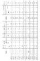
- FIG. 4 shows the results of evaluating the high-rate discharge cycle characteristics and the deterioration of the positive electrode lead paste.
- the lead storage batteries of Examples 1 to 10 had more than 300 cycles, but the batteries of Comparative Examples 1 to 4 had less than 150 cycles. From this, it was found that the lead storage battery of the present invention has an excellent high rate discharge cycle life.
- the bending degree (T / W) of the lattice is in the range of 1.50 to 1.90
- the overfilling rate (P / T) of the lead paste is in the range of 1.10 to 1.40.
- the lead storage battery inside provided good lead paste applicability and excellent high-rate discharge life. Further, as can be seen from the comparison results with Examples 3, 8, 9 and Examples 7, 10, the width / thickness of the lattice lines can be obtained even if the bending degree of the same lattice and the overfilling rate of the lead paste are provided.
- a battery having a ratio (W / t) in the range of 1.25 to 1.60 gave a better high rate discharge life.
Landscapes
- Chemical & Material Sciences (AREA)
- Chemical Kinetics & Catalysis (AREA)
- Electrochemistry (AREA)
- General Chemical & Material Sciences (AREA)
- Cell Electrode Carriers And Collectors (AREA)
- Secondary Cells (AREA)
- Battery Electrode And Active Subsutance (AREA)
Abstract
L'invention concerne une grille pour une batterie au plomb qui est configurée à partir d'une grille étendue formée par un procédé réciproque. Quand la largeur d'une ligne de grille (g) de la grille étendue est représentée par W et l'épaisseur de la grille étendue est représentée par T, la flexibilité (T/W) de la grille se situe dans une plage de valeurs entre 1,5 et 1,9.
Priority Applications (1)
| Application Number | Priority Date | Filing Date | Title |
|---|---|---|---|
| JP2012535477A JP5230845B2 (ja) | 2011-03-31 | 2012-04-02 | 鉛蓄電池用の極板群、鉛蓄電池、及び鉛蓄電池用の極板群の製造方法 |
Applications Claiming Priority (2)
| Application Number | Priority Date | Filing Date | Title |
|---|---|---|---|
| CN201110085830.5A CN102738470B (zh) | 2011-03-31 | 2011-03-31 | 铅蓄电池用格栅、正极板、极板组、铅蓄电池及其制造方法 |
| CN201110085830.5 | 2011-03-31 |
Publications (1)
| Publication Number | Publication Date |
|---|---|
| WO2012132476A1 true WO2012132476A1 (fr) | 2012-10-04 |
Family
ID=46930244
Family Applications (1)
| Application Number | Title | Priority Date | Filing Date |
|---|---|---|---|
| PCT/JP2012/002286 Ceased WO2012132476A1 (fr) | 2011-03-31 | 2012-04-02 | Grille pour batterie au plomb, plaque positive utilisant une grille, groupe de plaques, batterie au plomb, et procédé de fabrication de plaque positive pour batterie au plomb |
Country Status (3)
| Country | Link |
|---|---|
| JP (1) | JP5230845B2 (fr) |
| CN (1) | CN102738470B (fr) |
| WO (1) | WO2012132476A1 (fr) |
Families Citing this family (5)
| Publication number | Priority date | Publication date | Assignee | Title |
|---|---|---|---|---|
| CN103715397B (zh) * | 2013-12-07 | 2016-01-13 | 河南超威电源有限公司 | 一种板栅表面浸粘液及极板固化工艺方法 |
| CN104752643B (zh) * | 2013-12-27 | 2019-03-15 | 松下蓄电池(沈阳)有限公司 | 铅蓄电池 |
| CN106025383B (zh) * | 2016-05-24 | 2020-01-07 | 淄博火炬能源有限责任公司 | 阀控式铅酸蓄电池及其制备方法 |
| JP6456537B1 (ja) | 2018-02-28 | 2019-01-23 | 古河電池株式会社 | 鉛蓄電池用正極格子体及び鉛蓄電池 |
| CN116833263B (zh) * | 2023-09-01 | 2023-10-31 | 太原科技大学 | 燃料电池金属双极板辊冲复合成形工艺及精度调控方法 |
Citations (6)
| Publication number | Priority date | Publication date | Assignee | Title |
|---|---|---|---|---|
| JPS56114282A (en) * | 1980-02-14 | 1981-09-08 | Yuasa Battery Co Ltd | Pasted lead acid battery |
| JPS56149772A (en) * | 1980-04-18 | 1981-11-19 | Yuasa Battery Co Ltd | Grid for lead battery |
| JPS56159065A (en) * | 1980-05-13 | 1981-12-08 | Yuasa Battery Co Ltd | Grid for lead acid battery |
| JPS585969A (ja) * | 1981-07-02 | 1983-01-13 | Japan Storage Battery Co Ltd | 鉛蓄電池 |
| JPH09223502A (ja) * | 1996-02-19 | 1997-08-26 | Matsushita Electric Ind Co Ltd | 密閉形鉛蓄電池 |
| JP2001006685A (ja) * | 1999-06-18 | 2001-01-12 | Matsushita Electric Ind Co Ltd | 鉛蓄電池用エキスパンド格子体の製造方法 |
Family Cites Families (2)
| Publication number | Priority date | Publication date | Assignee | Title |
|---|---|---|---|---|
| US5582936A (en) * | 1994-11-16 | 1996-12-10 | Globe-Union, Inc. | Lead-acid batteries with optimum current collection at grid lugs |
| US5989749A (en) * | 1997-11-26 | 1999-11-23 | Johnson Controls Technology Company | Stamped battery grid |
-
2011
- 2011-03-31 CN CN201110085830.5A patent/CN102738470B/zh not_active Expired - Fee Related
-
2012
- 2012-04-02 JP JP2012535477A patent/JP5230845B2/ja not_active Expired - Fee Related
- 2012-04-02 WO PCT/JP2012/002286 patent/WO2012132476A1/fr not_active Ceased
Patent Citations (6)
| Publication number | Priority date | Publication date | Assignee | Title |
|---|---|---|---|---|
| JPS56114282A (en) * | 1980-02-14 | 1981-09-08 | Yuasa Battery Co Ltd | Pasted lead acid battery |
| JPS56149772A (en) * | 1980-04-18 | 1981-11-19 | Yuasa Battery Co Ltd | Grid for lead battery |
| JPS56159065A (en) * | 1980-05-13 | 1981-12-08 | Yuasa Battery Co Ltd | Grid for lead acid battery |
| JPS585969A (ja) * | 1981-07-02 | 1983-01-13 | Japan Storage Battery Co Ltd | 鉛蓄電池 |
| JPH09223502A (ja) * | 1996-02-19 | 1997-08-26 | Matsushita Electric Ind Co Ltd | 密閉形鉛蓄電池 |
| JP2001006685A (ja) * | 1999-06-18 | 2001-01-12 | Matsushita Electric Ind Co Ltd | 鉛蓄電池用エキスパンド格子体の製造方法 |
Also Published As
| Publication number | Publication date |
|---|---|
| JP5230845B2 (ja) | 2013-07-10 |
| CN102738470A (zh) | 2012-10-17 |
| CN102738470B (zh) | 2015-07-29 |
| JPWO2012132476A1 (ja) | 2014-07-24 |
Similar Documents
| Publication | Publication Date | Title |
|---|---|---|
| JP5106712B2 (ja) | 鉛蓄電池及び電動車両 | |
| EP2122725B1 (fr) | Grille négative pour batterie | |
| JP6162136B2 (ja) | 耐食性を変化させた電池グリッド | |
| CN100517819C (zh) | 蓄电池及其制备方法 | |
| JP5325358B1 (ja) | 電池用極板及びその製造方法、該極板を有する極板群並びに鉛蓄電池 | |
| JP5230845B2 (ja) | 鉛蓄電池用の極板群、鉛蓄電池、及び鉛蓄電池用の極板群の製造方法 | |
| JP2019153385A (ja) | 鉛蓄電池用正極格子体及び鉛蓄電池 | |
| JP2019029068A (ja) | 鉛蓄電池 | |
| KR100721638B1 (ko) | 납축전지용 격자체의 제조방법 및 납축전지 | |
| JP4092816B2 (ja) | 鉛蓄電池用格子体およびその製造方法 | |
| JP6921037B2 (ja) | 鉛蓄電池 | |
| JP2000348734A (ja) | 鉛蓄電池及びその製造法 | |
| CN202094213U (zh) | 铅蓄电池用格栅、正极板、极板组、以及铅蓄电池 | |
| JP4834912B2 (ja) | 蓄電池用格子体の製造方法と、その製造方法により製造した蓄電池用格子体を用いる鉛蓄電池の製造方法 | |
| JP2004273400A (ja) | 蓄電池用格子体とそれを用いた鉛蓄電池 | |
| JP5594039B2 (ja) | 鉛蓄電池用極板およびこれを用いた鉛蓄電池 | |
| JP2000348732A (ja) | 鉛蓄電池とその製造方法 | |
| JP2001135318A (ja) | 密閉鉛蓄電池用格子体及びその製造方法 | |
| CN101567463A (zh) | 蓄电池、膨胀栅格及其制备方法 | |
| JPH10188995A5 (fr) | ||
| JP2004192990A (ja) | 電池用エキスパンド格子体とそれを用いた電池および鉛蓄電池 | |
| HK1139237B (en) | Negative grid for battery |
Legal Events
| Date | Code | Title | Description |
|---|---|---|---|
| ENP | Entry into the national phase |
Ref document number: 2012535477 Country of ref document: JP Kind code of ref document: A |
|
| 121 | Ep: the epo has been informed by wipo that ep was designated in this application |
Ref document number: 12765638 Country of ref document: EP Kind code of ref document: A1 |
|
| NENP | Non-entry into the national phase |
Ref country code: DE |
|
| 122 | Ep: pct application non-entry in european phase |
Ref document number: 12765638 Country of ref document: EP Kind code of ref document: A1 |