WO2012132505A1 - Dispositif de colonne de direction - Google Patents
Dispositif de colonne de direction Download PDFInfo
- Publication number
- WO2012132505A1 WO2012132505A1 PCT/JP2012/051227 JP2012051227W WO2012132505A1 WO 2012132505 A1 WO2012132505 A1 WO 2012132505A1 JP 2012051227 W JP2012051227 W JP 2012051227W WO 2012132505 A1 WO2012132505 A1 WO 2012132505A1
- Authority
- WO
- WIPO (PCT)
- Prior art keywords
- steering
- steering wheel
- steering column
- vehicle body
- column
- Prior art date
- Legal status (The legal status is an assumption and is not a legal conclusion. Google has not performed a legal analysis and makes no representation as to the accuracy of the status listed.)
- Ceased
Links
Images











Classifications
-
- B—PERFORMING OPERATIONS; TRANSPORTING
- B62—LAND VEHICLES FOR TRAVELLING OTHERWISE THAN ON RAILS
- B62D—MOTOR VEHICLES; TRAILERS
- B62D1/00—Steering controls, i.e. means for initiating a change of direction of the vehicle
- B62D1/02—Steering controls, i.e. means for initiating a change of direction of the vehicle vehicle-mounted
- B62D1/16—Steering columns
- B62D1/18—Steering columns yieldable or adjustable, e.g. tiltable
- B62D1/184—Mechanisms for locking columns at selected positions
-
- B—PERFORMING OPERATIONS; TRANSPORTING
- B62—LAND VEHICLES FOR TRAVELLING OTHERWISE THAN ON RAILS
- B62D—MOTOR VEHICLES; TRAILERS
- B62D1/00—Steering controls, i.e. means for initiating a change of direction of the vehicle
- B62D1/02—Steering controls, i.e. means for initiating a change of direction of the vehicle vehicle-mounted
- B62D1/16—Steering columns
- B62D1/18—Steering columns yieldable or adjustable, e.g. tiltable
- B62D1/187—Steering columns yieldable or adjustable, e.g. tiltable with tilt adjustment; with tilt and axial adjustment
-
- B—PERFORMING OPERATIONS; TRANSPORTING
- B60—VEHICLES IN GENERAL
- B60R—VEHICLES, VEHICLE FITTINGS, OR VEHICLE PARTS, NOT OTHERWISE PROVIDED FOR
- B60R21/00—Arrangements or fittings on vehicles for protecting or preventing injuries to occupants or pedestrians in case of accidents or other traffic risks
- B60R21/02—Occupant safety arrangements or fittings, e.g. crash pads
- B60R21/09—Control elements or operating handles movable from an operative to an out-of-the way position, e.g. pedals, switch knobs, window cranks
-
- B—PERFORMING OPERATIONS; TRANSPORTING
- B62—LAND VEHICLES FOR TRAVELLING OTHERWISE THAN ON RAILS
- B62D—MOTOR VEHICLES; TRAILERS
- B62D1/00—Steering controls, i.e. means for initiating a change of direction of the vehicle
- B62D1/02—Steering controls, i.e. means for initiating a change of direction of the vehicle vehicle-mounted
- B62D1/16—Steering columns
- B62D1/18—Steering columns yieldable or adjustable, e.g. tiltable
- B62D1/19—Steering columns yieldable or adjustable, e.g. tiltable incorporating energy-absorbing arrangements, e.g. by being yieldable or collapsible
- B62D1/195—Yieldable supports for the steering column
-
- B—PERFORMING OPERATIONS; TRANSPORTING
- B62—LAND VEHICLES FOR TRAVELLING OTHERWISE THAN ON RAILS
- B62D—MOTOR VEHICLES; TRAILERS
- B62D1/00—Steering controls, i.e. means for initiating a change of direction of the vehicle
- B62D1/02—Steering controls, i.e. means for initiating a change of direction of the vehicle vehicle-mounted
- B62D1/16—Steering columns
- B62D1/18—Steering columns yieldable or adjustable, e.g. tiltable
- B62D1/19—Steering columns yieldable or adjustable, e.g. tiltable incorporating energy-absorbing arrangements, e.g. by being yieldable or collapsible
- B62D1/197—Steering columns yieldable or adjustable, e.g. tiltable incorporating energy-absorbing arrangements, e.g. by being yieldable or collapsible incorporating devices for preventing ingress of the steering column into the passengers space in case of accident
Definitions
- the present invention relates to a steering column device including a tilt mechanism for adjusting the vertical position of a steering wheel and a mechanism for protecting a driver from an impact caused by a secondary collision.
- the steering apparatus for an automobile transmits the rotation of the steering wheel 1 to the input shaft 3 of the steering gear unit 2, and pushes and pulls the pair of left and right tie rods 4 as the input shaft 3 rotates. And it is comprised so that a steering angle may be provided to a front wheel.
- the steering wheel 1 is supported and fixed at the rear end portion of the steering shaft 5.
- the steering shaft 5 is rotatably supported by the steering column 6 with the cylindrical steering column 6 inserted in the axial direction. ing. Further, the front end portion of the steering shaft 5 is connected to the rear end portion of the intermediate shaft 8 via the universal joint 7, and the front end portion of the intermediate shaft 8 is connected to the input shaft 3 via another universal joint 9. is doing.
- a tilt mechanism for adjusting the vertical position of the steering wheel 1 and a telescopic mechanism for adjusting the front-rear position according to the physique and driving posture of the driver have been widely applied.
- the steering column 6 is supported with respect to the vehicle body 10 so as to be capable of swinging displacement about the pivot 11 installed in the width direction.
- the width direction means the width direction of the vehicle body and coincides with the left-right direction.
- a displacement bracket fixed to a portion near the rear end of the steering column 6 is supported with respect to the support bracket 12 supported on the vehicle body 10 so as to be able to be displaced in the vertical direction and the front-rear direction.
- the front-rear direction means the front-rear direction of the vehicle body.
- the steering column 6 has a structure in which the outer column 13 and the inner column 14 are telescopically combined, and the steering shaft 5 is The outer shaft 15 and the inner shaft 16 are combined with each other so as to be able to transmit torque and expand and contract by spline engagement or the like.
- the illustrated example also incorporates an electric power steering device that reduces the force required to operate the steering wheel 1 using the electric motor 17 as an auxiliary power source.
- the position of the steering wheel 1 is made adjustable or fixed at an adjusted position based on the operation of the adjustment lever, except for an electric mechanism.
- the axial dimension of the cam device 20 is expanded and contracted simultaneously with the cam member 21 based on the rotation of the adjustment rod 19 by the adjustment lever 18.
- a structure for swinging and displacing is described.
- the structure of a cam device disclosed in Japanese Patent Application Laid-Open No. 2002-87286, in which the axial dimension is enlarged / reduced by an adjusting lever has been widely known.
- the displacement bracket 22 fixed to the outer column 13a is engaged with and disengaged from the support bracket 12a based on the expansion and contraction of the cam device 20. Further, based on the rocking displacement of the cam member 21, whether or not the inner column 14a can slide with respect to the outer column 13a is switched.
- the adjustment rod 19 is formed by inserting, in the width direction, a vertical hole 24 formed in the pair of left and right support plate portions 23 constituting the support bracket 12a and a front / rear direction long hole 25 formed in the displacement bracket 22. Yes.
- the adjustment lever 18 is moved in a predetermined direction.
- the cam device 20 is swung (generally downward) to reduce the axial dimension of the cam device 20, and the cam member 21 is separated from the outer peripheral surface of the inner column 14a.
- the cam device 20 is disposed at the axial end portion (left end portion in FIG.
- a drive cam 26 supported and fixed in a state in which both relative rotation and axial displacement are prevented, and an object to be supported that is capable of both relative rotation and axial displacement with respect to the adjustment rod 19 at an intermediate portion in the axial direction of the adjustment rod 19. And a driving cam 27.
- the adjustment rod 19 a that allows the cam device 20 a and the drive cam 26 a to be displaced only along the vertical slot 24 and prevents rotation about its own central axis. Further, it is supported in a state in which relative rotation with respect to the adjusting rod 19a is possible and axial displacement is prevented, and the driven cam 27a is in a state in which relative rotation with respect to the adjusting rod 19a is suppressed and axial displacement is suppressed.
- a structure that can be supported is also possible.
- the adjustment lever 18 in order to adjust the vertical position or the front-rear position of the steering wheel 1, the adjustment lever 18 is rotated in a predetermined direction, so that as shown in FIG. 26a) is engaged with the concave portion 29 provided on the driven cam 27 (27a), and the axial dimension of the cam device 20 is reduced.
- the outer column 13a is displaced within a range in which the adjustment rod 19 (19a) can be displaced within the vertical slot 24 and the longitudinal slot 25. Then, the position of the steering wheel 1 supported and fixed to the rear end portion of the steering shaft 5a rotatably supported in the outer column 13a is adjusted.
- the adjustment lever 18 is swung in a direction opposite to the predetermined direction, and is provided on the drive side cam 26 (26a) as shown in FIG.
- the convex portion 28 is engaged with a stepped portion 30 provided on the driven cam 27 (27a), and the axial dimension of the cam device 20 (20a) is expanded.
- the outer peripheral surface of the inner column 14a is simultaneously suppressed by the cam member 21.
- the inner diameter of the outer column 13a is reduced. As a result, in any structure, the steering wheel 1 is held at the adjusted position.
- a structure having a mechanism for protecting a driver from an impact caused by a secondary collision in which the driver collides with the steering wheel in a vehicle collision accident as shown in FIG. 35 has been conventionally known. It has been.
- the entire length of the steering shaft 5b and the steering column 6a is reduced, so that the impact caused by the secondary collision is reduced.
- the support bracket 12b that supports the outer column 13a is disengaged forward from the vehicle body 10 (see FIG. 30), and the overall length of the steering column 6a is reduced. Allow that.
- the steering column 6a may be displaced upward along these vertical holes 24a. That is, a component force in a direction perpendicular to the central axis of the steering column 6a is generated by the impact load accompanying the secondary collision.
- the attachment angle ⁇ is larger than the inclination angle ⁇ , this component force increases, and when a force larger than the tightening force by the adjustment rod 19b and the cam device 20 (20a) is applied, the adjustment rod 19b. May be displaced upward along the up-down direction long hole 24a, and the steering column 6a may be displaced upward.
- the collision position between the airbag installed on the steering wheel 1 and the driver deviates from the normal position, and the impact mitigating effect by this airbag may not be sufficiently obtained.
- the head may not be supported by the airbag.
- the force acting at the time of the secondary collision is not efficiently transmitted in the direction in which the entire length of the steering column 6a is contracted, and the shock absorption due to the contraction of the entire length of the steering column 6a cannot be performed smoothly.
- the vehicle body 10 does not come off smoothly and the shock absorbing performance is not stably exhibited.
- Japanese Patent Application Laid-Open No. 2010-52639 discloses a steering column 6b regardless of the vertical position of the steering wheel 1, as shown in FIG. A technique is described in which the inclination angle ⁇ of the vertical elongated hole 24b with respect to the virtual plane A orthogonal to the central axis is larger than the inclination angle ⁇ of the central axis of the steering column 6b with respect to the front-rear direction B ( ⁇ > ⁇ ). .
- the adjusting rod 19b in order to displace the adjusting rod 19b to the upper side of the vehicle body even when an impact force directed to the upper side of the vehicle body is input to the adjusting rod 19b, against the collapse load acting in the axial direction, the adjusting rod 19b must be moved backward along the axial direction of the steering column 6b to prevent the outer column 13a from being displaced upward.
- the airbag can effectively catch the driver.
- the steering column device of this document is provided with a telescopic mechanism, and a longitudinal bracket 22 is provided in the displacement bracket 22. Therefore, the steering column 6b starts to move from the vehicle body mounting bracket 12c to the vehicle body front side against the tightening force due to an impact load applied to the vehicle body front side at the time of the secondary collision. That is, in the state where the friction of the fastening surface that fastens the steering column 6b to the vehicle body mounting bracket 12c is changed from static friction to dynamic friction, the tilted vertical slot 24b prevents the steering column 6b from being displaced upward. As a result, the function of preventing displacement above the steering column 6b may be reduced.
- the vertically elongated hole 24b is disposed on the vehicle body lower side with respect to the central axis of the steering column 6b. Accordingly, the distance from the mounting surface of the support bracket 12c to the vehicle body to the adjustment rod 19 is long, and the locking capsule 34 is distorted by the impact load to the front side of the vehicle body at the time of the secondary collision. There is also a risk that the shock absorbing performance will not be stable.
- the following problems may occur. That is, the state in which the vertical position or the front / rear position of the steering wheel 1 can be adjusted and the state in which these positions are maintained are switched by expanding / contracting the axial dimension of the cam device 20 (20a) described above.
- the driving side cam 26 (26a) and the driven side cam 27 (27a) of the cam device 20 (20a) one member is supported so as to be rotatable relative to the adjusting rod 19b, and the other member is not allowed to rotate relative to the adjusting rod 19b. It is supported by.
- the driven cam 27 (27a) is engaged with the vertical long hole 24b so that only displacement along the vertical long hole 24b is possible.
- an object of the present invention is to provide a support bracket for supporting a steering column on a vehicle body at the time of a secondary collision while preventing the steering column from being displaced upward at the time of a secondary collision.
- An object of the present invention is to provide a steering column device that can be smoothly detached from the vehicle.
- Another object of the present invention is to realize a structure in which the distance between the steering column and the tip of the adjusting lever can be made the same regardless of the vertical position of the steering wheel in the apparatus capable of obtaining such an effect. It is said.
- the steering column device includes: A steering column that pivotally supports a steering shaft on which a front end portion is supported on the vehicle body side so as to be capable of swinging displacement about a pivot installed in the width direction and a steering wheel is mounted; A displacement bracket fixed to the intermediate portion of the steering column in the axial direction and provided with a through hole formed in the width direction; A pair of support plate portions, and a pair of vertically elongated holes formed in portions of the pair of support plate portions that are aligned with the through-holes, and the pair of support plate portions A support bracket supported on the vehicle body side with the displacement bracket sandwiched from the left and right; A hook-shaped member that is inserted into the through hole and the pair of vertically elongated holes and is displaceable along the vertically elongated hole; An adjustment comprising a main body portion having a base end portion connected to an end portion of the hook-shaped member and a tip portion positioned away from the base end portion, and capable of rotating the hook-shaped member.
- the cam device is supported at the end of the bowl-shaped member in a state in which axial displacement is suppressed, and can be rotated based on an operation of the adjustment lever.
- the one of the pair of vertically elongated holes is engaged with only the displacement along the vertically elongated hole so as to be supported, and is supported by the saddle-like member axially intermediate portion so as to be capable of axial displacement.
- a driven cam a driven cam.
- the cam device can expand and contract the axial dimension of the pair of support plate portions as the driving cam rotates with respect to the driven cam. .
- the steering column device of the present invention can adjust the vertical position of the steering wheel, and can displace the steering column forward in the event of a secondary collision. It is designed to support the vehicle body.
- the vertical slot is inclined at a predetermined angle with respect to a virtual plane orthogonal to the central axis of the steering column, and becomes longer in a downward direction toward the front,
- the predetermined angle is larger than the inclination angle of the central axis of the steering column with respect to the front-rear direction regardless of the vertical position of the steering wheel;
- a stopper step portion is provided on the outer surface of the support plate portion facing the adjustment lever, and a base end portion of the adjustment lever has a steering wheel In a state where the adjustment lever is positioned in a state where the vertical position can be maintained, the bumper hits the stepped portion for stopper, and in a state where the vertical position of the steering wheel can be adjusted, the adjustment lever is positioned.
- a locking arm provided with a tip portion is provided apart from the stepped portion for stopper,
- the extending direction of the stepped portion for the stopper is inclined at a predetermined angle with respect to the extending direction of the up-and-down elongated hole, and the stopper for which the tip end portion of the locking arm comes into contact with the vertical position of the steering wheel
- the state in which the vertical position of the steering wheel can be maintained means that the adjustment lever is rotated in a predetermined direction (generally upward) to expand the axial dimension of the cam device. In this state, the distance between the pair of support plate portions is reduced, and the displacement bracket is sandwiched from the left and right by these support plate portions.
- the state in which the vertical position of the steering wheel can be adjusted means that the adjustment lever is rotated in a direction opposite to the predetermined direction (generally downward), and the axial dimension of the cam device is reduced. The interval between the pair of support plate portions is expanded, and the pair of support plate portions and the displacement bracket are separated from each other.
- the adjustment lever is configured so that the stepped portion for the stopper and the vertical position of the steering wheel can be adjusted on the outer surface of the support plate portion facing the adjustment lever.
- a convex portion is provided between the flat portion and the front end portion of the locking arm between the convex portion and the stepped portion for stopper. Is formed so that the front end of the locking arm can easily ride on the convex portion on both side surfaces of the convex arm in the rotation direction. It is preferable to provide an inclined surface portion.
- the distal end portion of the locking arm engages with the upper end portion of the locking groove, and the vertical position of the steering wheel is set to the lower side.
- the distal end portion of the locking arm engages with the lower end portion of the locking groove.
- the rigidity of the locking arm is lower than the rigidity of the main body portion of the adjusting lever.
- the steering column device of the second aspect of the present invention basically includes a steering column, a support bracket, a hook-shaped member, an adjustment lever, and a cam device, as in the conventional structure and the device of the first aspect.
- the steering column is supported on the vehicle body side so that the vertical position of the steering wheel can be adjusted and the steering column can be displaced forward during a secondary collision.
- the vertical slot is rearward of the vehicle body with respect to a plane orthogonal to a straight line connecting the pivot center of the steering column (center of the pivot) and the center of the bowl-shaped member. It is characterized by being inclined to the side.
- the steering column includes an outer column and an inner column fitted to the outer column so that the outer peripheral surface is slidable on the inner peripheral surface of the outer column, and the pair of support plate portions In a state in which the distance between the outer column and the inner column is expanded, the inner circumferential surface of the outer column is preferably expanded so that the outer column and the inner column can move relative to each other in the axial direction.
- the steering column device may be provided with not only a tilt mechanism but also a telescopic mechanism that enables adjustment of the front-rear position of the steering wheel.
- the outer column or the displacement bracket fixed to the outer column is provided with a front / rear direction elongated hole extending in the front / rear direction, and a side connected to the adjustment lever at both ends of the bowl-shaped member; Between the head provided at the opposite end and the outer surface of the support plate facing the head of the pair of support plates, there are a plurality of friction plates for telescoping with each other. It is preferable that it is arranged.
- the hook-like member is disposed above the center axis of the steering column and the vehicle body is located on the upper side of the vehicle body. It is formed so as to be inclined to the rear side of the vehicle body with respect to a plane orthogonal to a straight line connecting the center of movement and the center of the bowl-shaped member.
- the support bracket since the distance from the mounting surface of the support bracket to the vehicle body side to the flange-like member is short, the support bracket is caused to collide with the vehicle body side by the impact load to the vehicle body front side at the time of the secondary collision.
- the capsule for detachably supporting the front side of the vehicle body is distorted, and the support bracket can be smoothly detached from the capsule. As a result, the function of reducing the impact load applied to the driver at the time of the secondary collision is effectively exhibited.
- the present invention it is possible to make the distance between the steering column and the tip of the adjusting lever the same regardless of the vertical position of the steering wheel while preventing the steering column from being displaced upward during a secondary collision. . Therefore, regardless of the vertical position of the steering wheel, the distance between the tip of the adjustment lever and the steering column is prevented from changing, and the amount of protrusion of the adjustment lever from the column cover that covers the steering column device It is possible to prevent the driver from feeling uncomfortable.
- FIG. 1 is a side view showing a first example of the first embodiment of the present invention.
- FIG. 2 is an enlarged view of the center of FIG.
- FIG. 3 is a perspective view of the right half of FIG. 1 as viewed from below.
- FIG. 4 is a perspective view of the main part of the first example of the first embodiment as viewed from below.
- FIG. 5 is a side view showing a first example of the first embodiment with the adjustment lever removed.
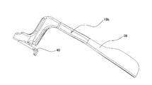
- FIG. 6 is a perspective view of the adjusting lever taken out from the first example of the first embodiment and viewed from below.
- FIG. 7 is a plan view of the adjustment lever shown in FIG.
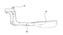
- FIG. 8 is a side view of the adjustment lever shown in FIG.
- FIG. 9 is a view of the adjustment lever shown in FIG. 6 as viewed from the rear.
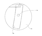
- FIG. 10 is a schematic diagram for explaining the operation of the cam device incorporated in the first example of the first embodiment.
- FIG. 11 is a side view which shows the state (A) which made the steering wheel the upper direction, and the state (B) which made the steering wheel the downward direction about the 1st example of 1st Embodiment.
- FIG. 12 is a side view showing a second example of the first embodiment of the present invention.
- FIG. 13 is a view similar to FIG. 5 showing a second example of the first embodiment.
- FIG. 14 is an enlarged view of a portion X in FIG.
- FIG. 15 is a front view showing a steering column device of a first example of the second embodiment of the present invention.
- 16 is a cross-sectional view taken along the line CC of FIG. FIG.
- FIG. 17A is a front view of a single outer column of the steering column device of the first example of the second embodiment
- FIG. 17B is a plan view of FIG.
- FIG. 18 is a front view of the vehicle body mounting bracket of the steering column device of the first example of the second embodiment.
- FIG. 18 is a front view showing a modified example of the vehicle body mounting bracket applied to the first example of the second embodiment.
- FIG. 20 is a front view showing a steering column device of a second example of the second embodiment of the present invention.
- 21 is a cross-sectional view taken along the line DD of FIG. 22 is a rear view of FIG.
- FIG. 23 is a perspective view of the steering column device of the second example of the second embodiment as viewed from above the vehicle body rear side.
- FIG. 24 is an exploded perspective view in which a part of FIG. 23 is exploded.
- FIG. 25 is a front view showing a steering column device of a third example of the second embodiment of the present invention.
- 26 is a cross-sectional view taken along line EE in FIG. 27 is a rear view of FIG.
- FIG. 28 is a perspective view of the steering column device of the third example of the second embodiment as viewed from above the vehicle body rear side.
- FIG. 29 is an exploded perspective view in which a part of FIG. 28 is exploded.
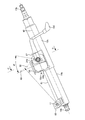
- FIG. 30 is a partially cut schematic side view of a steering apparatus that includes a telescopic mechanism and a tilt mechanism, which is conventionally known.
- FIG. 31 is a longitudinal side view showing a second example of the conventional structure.
- FIG. 31 is a longitudinal side view showing a second example of the conventional structure.
- FIG. 32 is an enlarged YY sectional view of FIG.
- FIG. 33 is a view similar to FIG. 32, showing a third example of the conventional structure.
- FIG. 34 is a schematic diagram for explaining the operation of the cam device.
- FIG. 35 is a side view showing a fourth example of the conventional structure.
- FIG. 36 is a side view showing a state in which the steering wheel is upward in the fifth example of the conventional structure.
- FIG. 1 to 11 show a first example of the first embodiment of the present invention.
- the features of the steering column device according to the first embodiment of the present invention including this example are related to the vertical position of the steering wheel 1 in a structure that prevents the steering column 6c from being displaced upward during a secondary collision.
- a structure in which the distance D between the steering column 6c and the tip of the lever portion 36 of the adjusting lever 18b is the same is realized.
- the distance D is the same includes a case where there is only a small difference that does not give the driver a sense of incongruity. Since the configuration and operation of the other parts are the same as those of a conventionally known steering column device, the illustration and explanation of the equivalent parts are omitted or simplified, and the following description will focus on the characteristic parts of this example.
- the weight of the portion that moves up and down together with the steering column 6c is supported and fixed to the support bracket 12c that is a portion fixed to the vehicle body 10 (see FIG. 30) and the front end portion of the steering column 6c. It swings with the steering column 6c, and is supported by a balance spring 33 installed between a housing 32 provided with a through hole 31 for inserting the pivot 11 (see FIG. 30) at the front end. For this reason, even when the position of the steering wheel 1 is adjusted, it is not necessary for the driver to support the entire weight of the steering column device. Further, an energy absorbing member 35 is provided between the support bracket 12c that is displaced forward together with the outer column 13b at the time of the secondary collision, and the locking capsule 34 that is not displaced forward at the time of the secondary collision.
- the base end is connected to one end of the adjustment rod 19b, which is a rod-shaped member, and the rod-like adjustment extends from the base end to the tip positioned away from the base end.
- the adjustment rod 19b is provided with a vertically elongated hole 24b formed in the support bracket 12c, and an outer column.
- the outer column 13b is displaced within a range that can be displaced in the longitudinal hole 25a formed in the front and rear direction 13b. Then, the position of the steering wheel 1 supported and fixed to the rear end portion of the steering shaft 5b rotatably supported in the outer column 13b is adjusted.
- the lever portion 36 is rotated upward to extend the axial dimension of the cam device 20b.
- the cam device 20b expands and contracts the axial dimension as the lever portion 36 of the adjustment lever 18b rotates.
- the cam device 20b itself does not have a function of regulating the rotation amount of the adjustment lever 18b.
- a click feeling moderate feeling
- the amount that the drive-side convex portion 37 rides on the driven-side convex portion 38 is the smallest, and even when the steering wheel 1 is at the lowest position, the drive-side convex portion 37 and the driven-side convex portion The tip surfaces of the portions 38 are in contact with each other with a sufficient area so that the state in which the axial dimension of the cam device 20b is expanded can be sufficiently maintained.
- the cam device 20b expands and contracts in the axial direction.
- the driving cam 26 (26a) is more than a predetermined angle with respect to the driven cam 27 (27a).
- the stopper surface 39 that prevents the rotation is not provided.
- the adjustment lever 18b is excessively rotated, and the axial dimension of the cam device 20 (20a) is reduced. It may shrink again.
- even if the amount of rotation of the adjusting lever 18b is appropriate, it is not possible to give a sense of moderation to those who operate the adjusting lever 18b.
- the amount of rotation of the adjustment lever 18b is properly regulated, a sense of moderation is given to the person who operates the adjustment lever 18b, and the adjustment lever 18b is rotated to a position where the steering wheel 1 can be held at the adjusted position.
- a pair of locking arms 40 is provided at the base end of the adjustment lever 18b, and the outer column 13b provided on the support bracket 12c is sandwiched from the width direction.
- the locking piece 41 is provided on the outer surface of one support plate portion 23a facing the adjustment lever 18b.
- the locking arm 40 is made thinner than the lever portion 36, so that the rigidity of the adjusting lever 18b is lower than the remaining portion (main body portion) excluding the locking arm 40.
- the locking piece 41 is made by injection molding of a synthetic resin, casting or forging of a metal material such as a light alloy, or by bending a metal plate, and is almost in the same direction as the vertically elongated hole 24b.
- a long locking groove 42 is provided. The locking groove 42 engages with the distal end portion of the locking arm 40 in a state where the adjustment lever 18b is rotated downward.
- the height dimension of the inner side surface on the opposite side to the up-and-down direction long hole 24b is enlarged among the width direction both inner side surfaces of the latching ditch
- the tip of the locking arm 40 abuts against the stopper step 47 in a state where the adjustment lever 18b is rotated downward.
- the stopper step portion 47 is provided directly on one of the support plate portions 23a of the pair of support plate portions 23a provided with the displacement bracket 22 interposed therebetween. You can also.
- such a locking groove 42 is adjusted in a state in which the adjustment lever 18 b is rotated downward and the distal end portion of the locking arm 40 of the adjustment lever 18 b is engaged.
- the distance D between the tip of the lever portion 36 of the lever 18b and the steering column 6c is always the same.
- the locking groove 42 and the stopper stepped portion 47 are inclined rearward by a predetermined angle with respect to the up-down direction long hole 24b (the upward direction is the backward direction). In a larger state).
- the upper end portion of the locking groove 42 and the tip end portion of the locking arm 40 are engaged, preferably (particularly, when the locking groove 42 is not provided).
- the front end of the locking arm 40 is abutted against the upper end of the stopper step 47.
- the phase of the driven cam 27b is shifted as shown by a one-dot chain line x in FIG. 10A.
- the drive side convex part 37 of the cam 26b increases the amount of riding on the driven side convex part 38 of the driven cam 27b.
- the lower end portion of the locking groove 42 and the tip end portion of the locking arm 40 are engaged, preferably (particularly, the locking groove 42 is not provided). ), The tip of the locking arm 40 is brought into contact with the lower end of the stepped portion 47 for stopper.
- the phase of the driven cam 27b is shifted as shown by a two-dot chain line y in FIG. 10A, but as shown in FIG. 10B.
- the amount by which the driving side convex portion 37 of the driving side cam 26b rides on the driven side convex portion 38 of the driven side cam 27b is reduced.
- the amount of rotation of the adjustment lever 18b does not change regardless of the vertical position of the steering wheel 1, and therefore the distance D between the steering column 6c and the tip of the lever portion 36 of the adjustment lever 18b is the same. Can do.
- the adjustment lever 18 b when the adjustment lever 18 b is rotated downward, the tip of the locking arm 40 and the flat provided on the locking piece 41 are provided.
- the adjustment lever 18b is prevented from rotating more than necessary by lightly contacting the portion 43 with the elasticity of the locking arm 40. Thereby, the adjustment lever 18b does not droop down greatly.
- the structure for locking the locking arm 40 at this position is not limited to such a flat surface 43, and other locking structures can be employed.
- a mountain-shaped convex portion 45 having a pair of inclined surface portions 44 a and 44 b inclined in the rotation direction of the locking arm 40 is provided between the locking groove 42 and the flat portion 43.
- the inclined surface portion 44a on the side of the concave groove 42 protrudes toward the direction in which the locking arm 40 moves when the adjustment lever 18b is rotated downward.
- the inclined surface portion 44b on the flat portion 43 side is inclined in the direction in which the height of the convex portion 45 increases, and the height of the convex portion 45 increases toward the direction in which the locking arm 40 moves when the adjustment lever 18b is rotated upward. It is inclined in the direction of increasing.
- the convex portion 45 of the mountain shape together with the stepped portion 47 for the stopper is connected to one of the pair of support plate portions 23a provided with the displacement bracket 22 interposed therebetween. It can also be provided directly on the support plate portion 23a.
- the distance D between the steering column 6c and the tip of the lever portion 36 of the adjusting lever 18b can be made the same regardless of the vertical position of the steering wheel 1. For this reason, when the distance D fluctuates, it is possible to prevent the amount of protrusion of the adjusting lever 18b from a column cover (not shown) covering the steering column device from changing, and giving the driver an uncomfortable feeling.
- the tip of the locking arm 40 of the adjustment lever 18 b is brought into contact with the flat portion 43 of the locking piece 41 while the adjustment lever 18 b is rotated downward. Since the contact is made, the adjustment lever 18b does not rotate more than necessary. For this reason, after moving the steering wheel 1 to a desired position, the operation of turning the adjustment lever 18b upward can be easily performed.
- the locking concave portion is provided.
- a relatively steep inclined surface portion 44a is provided on the groove 42 side, and the width dimension of the bottom portion of the locking concave groove 42 is set to be equal to or smaller than the width dimension of the distal end portion of the locking arm 40. It is possible to prevent the adjusting lever 18b from rattling in a state where the concave groove 42 is engaged. Furthermore, it is possible to prevent the adjusting lever 18b from rotating carelessly from the state in which the steering wheel 1 is held at the adjusted position.
- the lever portion 36 of the adjustment lever 18b is operated (rotated) after the steering wheel 1 is moved to a desired position. In doing so, it is possible to improve the operational feeling of the adjusting lever 18b by imparting an appropriate resistance to this rotation.
- the resistance against the rotation of the adjusting lever 18b can be adjusted by adjusting the inclination angles of the inclined surface portions 44a and 44b. Therefore, by adjusting the inclination angles of these inclined surface portions 44a and 44b, the operational feeling of the adjusting lever 18b can be tuned according to the vehicle.
- the inclined surface portions 44a and 44b may be formed by combining a plurality of inclined surfaces, or the cross-sectional shape may be a partially arcuate inclined surface.
- the driver's knee portion is at the tip of the lever portion 36 of the adjusting lever 18b at the time of a secondary collision. With the impact load at the time of collision, the locking arm 40 is broken. Then, the adjustment lever 18b is allowed to rotate, and the knee portion colliding with the adjustment lever 18b is protected. Since the knee portion can be protected by breaking the locking arm 40, the rigidity of the lever portion 36 which is the remaining portion (main body portion) can be sufficiently increased.
- FIG. 5 shows a second example of the first embodiment of the present invention.
- the steering column device of this example includes a tilt mechanism but does not include a telescopic mechanism. That is, the front / rear direction long hole 25b (see FIG. 5) is not provided. For this reason, the outer column 13b can be displaced in the axial direction due to the impact load at the time of the secondary collision, and can be slightly displaced in the axial direction along with the vertical position adjustment along the vertical hole 24c. Regardless of the position adjustment, the front-rear position adjustment cannot be performed independently.
- the upper half of the vertically elongated hole 24c is represented by a chain arc in FIG. 14 with respect to a partially arc-shaped elongated hole centering on the pivot 11 (see FIG. 30) inserted through the through hole 31.
- the shape of the locking arm 40a of the adjusting lever 18c and the shape of the locking groove 42a of the locking piece 41a are matched to the shape of the vertically elongated hole 24c. Is different. Further, in order to adjust the vertical position of the steering wheel 1 (see FIG.
- the adjustment lever 18c is turned downward, and is bent downward in front of the locking arm 40a and the support bracket 12d.
- the adjustment lever 18c is prevented from rotating more than necessary by contacting the rear side surface of the provided hanging plate portion 46.
- the structure and operation of the other parts are the same as in the first example of the first embodiment.
- 1st Embodiment of this invention is applied to the structure which provides this displacement bracket in the lower part of this steering bracket. It is also possible to do so.
- the displacement bracket is provided at the lower part of the steering bracket, the distance from the mounting surface of the support bracket to the vehicle body to the adjustment rod becomes long, and the impact load on the front side of the vehicle during a secondary collision causes the locking capsule to
- the first embodiment of the present invention be applied to a structure in which the displacement bracket is provided on the upper portion because the support bracket may not be smoothly detached from the vehicle body and the shock absorption performance may not be stable due to stagnation.
- 1st Embodiment to the structure of 2nd Embodiment demonstrated below.
- FIG. 15 to 18 show a first example of the second embodiment of the present invention.
- the outer column 13c is fitted to the outer periphery of the inner column 14b disposed on the front side of the vehicle body so as to be slidable in the axial direction.
- An outer shaft (upper steering shaft) 15b is rotatably supported on the outer column 13c, and the steering wheel 1 is fixed to the right end (rear side of the vehicle body) of the outer shaft 15b.
- the outer column 13c is an integrally molded product made of an aluminum alloy die-cast, but may be a steel pipe welded with a displacement bracket (distance bracket). Further, for the purpose of weight reduction, it may be made of a magnesium alloy die casting.
- a support bracket (vehicle body mounting bracket) 12d is attached to the left side (front side of the vehicle body) of the outer column 13c so as to sandwich the outer column 13c from both the left and right sides.
- the support bracket 12d is detachably attached to the front side of the vehicle body via a capsule 68 made of aluminum alloy or the like fixed to the vehicle body 67 (see FIG. 16).
- the support bracket 12d In the outer column 13c, when a driver collides with the steering wheel 1 during a secondary collision and a large impact force is applied, the support bracket 12d is detached from the capsule 68 toward the front side of the vehicle body, and is guided to the inner column 14b. It collapses to absorb the impact energy.
- the lower bracket 60 is integrally fixed to the vehicle body front side (left side) of the inner column 14b.
- the lower bracket 60 is supported by the vehicle body 67 via a pivot (pivot pin) 11 so as to be tiltable.
- An inner shaft (lower steering shaft) 16b is rotatably supported on the inner column 14b, and the vehicle body rear side of the inner shaft 16b is spline-engaged with the vehicle body front side of the outer shaft 15b.
- the inner shaft 16b is connected to the steering gear unit 2 via the intermediate shaft 8, and can change the steering angle of the wheel.
- the support bracket 12d has an upper plate 64 and a pair of support plate portions 23b extending downward from the upper plate 64.
- the outer column 13c is integrally formed with a displacement bracket (distance bracket) 57 that protrudes above the outer column 13c.
- the side surfaces 58 of the displacement brackets 57 are slidably in contact with the inner side surfaces 65 of the pair of support plate portions (side plates) 23b of the support bracket 12d.
- the outer column 13c is formed with a slit 56 communicating with the inner peripheral surface 52 of the outer column 13c.
- the support plate portion 23b of the support bracket 12d is formed with a vertical hole (tilt adjustment long groove) 24d.
- the vertically long hole 24d is formed on the vehicle body upper side with respect to the central axis 48 of the outer column 13c, and is inclined to the vehicle body rear side from the vehicle body lower side toward the vehicle body upper side.
- the up-and-down direction long hole 24d is formed so as to be inclined toward the rear side of the vehicle body with respect to the arc 50 centered on the pivot 11.
- a round hole 59 extending in the left-right direction in FIG. 16 is formed as a through hole on the vehicle body upper side than the central axis 48 of the outer column 13c.
- a round rod-shaped adjustment rod (clamping rod) 19c which is a bowl-shaped member, is inserted from the right side of FIG. 16 through the vertical elongated hole 24d and the round hole 59.
- the up-and-down direction long hole 24d is formed so as to be inclined to the rear side of the vehicle body by an inclination angle ⁇ with respect to a plane 49 orthogonal to a straight line 51 connecting the center of the pivot 11 (the pivot center) and the center of the adjustment rod 19c. .
- a cylindrical head 69 is formed at the right end of the adjusting rod 19c.
- a driven cam (fixed cam) 27c, a driving cam (movable cam) 26c, and an adjusting lever 18d are externally fitted in this order on the left end of the adjusting rod 19c outside the outer surface 66 of the support plate portion 23b.
- a female screw (not shown) formed on the inner diameter portion of the nut 70 is screwed into a male screw 71 formed on the left end of the adjusting rod 19c, and the right end surface of the nut 70 is in contact with the adjusting lever 18d.
- Complementary inclined cam surfaces are formed on the opposed end surfaces of the driven cam 27c and the driving cam 26c and mesh with each other.
- the support plate portion 23b is pushed rightward by the right end surface of the driven cam 27c, the support plate portion 23b is deformed inward, and the inner side surface 65 of the support plate portion 23b is strongly pressed against the side surface 58 of the displacement bracket 57.
- the right-side head 69 presses the outer surface 66 of the support plate portion 23b to deform the support plate portion 23b inward, and strongly presses the inner surface 65 of the support plate portion 23b against the side surface 58 of the displacement bracket 57. .
- the displacement bracket 57 of the outer column 13c can be firmly fastened to the support bracket 12d. Then, the width of the slit 56 of the outer column 13c is narrowed, the inner peripheral surface 52 of the outer column 13c is reduced in diameter, the inner peripheral surface 52 of the outer column 13c is tightened to the outer peripheral surface of the inner column 14b, and the outer column 13c is The relative movement with respect to the inner column 14b is prevented. In this manner, the outer column 13c is fixed to the support bracket 12d, and displacement of the outer column 13c in the tilt direction is prevented.
- the outer column 13c is in a free state with respect to the support plate portion 23b of the support bracket 12d. Therefore, the tilt direction of the steering wheel 1 can be arbitrarily adjusted by displacing the adjustment rod 19c in the vertical direction (tilt direction) while guiding the adjustment rod 19c through the vertical hole 24d.
- the up-and-down direction long hole 24d is formed so as to incline toward the rear side of the vehicle body by an inclination angle ⁇ with respect to a plane 49 orthogonal to a straight line 51 connecting the center of the pivot 11 (the pivot center) and the center of the adjustment rod 19c. . Therefore, even if an impact force directed toward the upper side of the vehicle body is input to the outer column 13c, the outer column 13c is disposed on the rear side of the vehicle body in the column axial direction against the collapse load in the column axial direction toward the front side of the vehicle body that acts simultaneously. The rear column 13c must be moved backward, and the outer column 13c can be prevented from moving upward in the vehicle body, and the airbag can effectively catch the driver.
- the outer column 13c is not provided with a longitudinal hole (telescopic adjustment long groove) as a through hole, and a round hole 59 is formed instead. Therefore, the outer column 13c does not start moving from the support bracket 12d to the front side of the vehicle body against the tightening force due to an impact load to the front side of the vehicle body at the time of the secondary collision. Therefore, the friction of the tightening surface (the inner surface 65 of the support plate portion 23b) that tightens the outer column 13c (the side surface 58 of the displacement bracket 57) to the support bracket 12d maintains a static friction state, so the outer column 13c is tilted upward. There is no risk that the ability to stop moving to the side will be reduced.
- the vertically elongated hole 24d is disposed on the vehicle body upper side with respect to the central axis 48 of the outer column 13c. Therefore, the distance from the mounting surface of the support bracket 12d to the vehicle body 67 to the adjustment rod 19c is short, and there is little risk of sag in the capsule 68 due to the impact load on the vehicle body front side at the time of the secondary collision. By smoothly detaching from the capsule 68, the impact load applied to the driver can be reduced.
- FIG. 19 is a front view showing a modified example of the support bracket.
- the vertical hole 24d is formed in a straight line shape, but is not limited to a straight line shape, and may be formed in an arc shape. That is, as indicated by a solid line in FIG. 19, the support plate portion 23b of the support bracket 12d is formed with an arc-shaped vertical elongated hole 24e.
- a conventional long groove 24 for tilt adjustment shown by a two-dot chain line in FIG. 19 is formed in an arc shape centered on the pivot 11.
- the vertically long hole 24e is formed in an arc shape centering on a center 61 spaced from the pivot 11 to the upper side of the vehicle body. Therefore, the vertical elongate hole 24e is formed on the vehicle body upper side than the central axis 48 of the outer column 13c, and is inclined to the vehicle body rear side from the vehicle body lower side toward the vehicle body upper side.
- the up-down direction long hole 24e is formed so as to be inclined to the rear side of the vehicle body with respect to the arc-shaped up-down direction long hole 24 having the pivot 11 as the center.
- FIG. 20 to 24 show a second example of the second embodiment of the present invention.
- the steering column device of the present example has not only a tilt function but also a telescopic function, and is therefore characterized in that a telescopic friction plate for increasing clamp rigidity in the front-rear direction (telescopic direction) is attached.
- the rear end of the vehicle body of the housing 32 of the steering assisting portion 53 (electric assist mechanism) is fixed by press-fitting to the front side of the inner column 14b.
- the steering assisting portion 53 includes the electric motor 17, a reduction gear box portion 62, an output shaft 63, and the like.
- the steering assisting portion 53 is supported by the vehicle body 67 via the pivot 11 so as to be tiltable.
- the steering assist unit 53 detects the torque acting on the inner shaft, drives the electric motor 17, rotates the output shaft 63 with a required steering assist force, and passes the intermediate shaft 8 to the steering gear unit 2. It is connected.
- the support bracket 12d has an upper plate 64 and a support plate portion 23b extending downward from the upper plate 64.
- a displacement bracket (distance bracket) 57 is integrally formed on the outer column 13c so as to protrude above the outer column 13c.
- the side surface 58 of the displacement bracket 57 in the vehicle width direction is slidably in contact with the inner side surface of the support plate portion (side plate) 23b of the support bracket 12d.
- a longitudinal hole (telescopic adjustment long groove) 25b is formed in the side surface 58 of the displacement bracket 57, and is long in the axial direction (telescopic position adjustment direction) of the outer column 13c.
- the support plate portion 23b of the support bracket 12d is formed with a vertically long hole 24d.
- a rod-shaped adjusting rod 19c which is a bowl-shaped member, is inserted from the right side of FIG. 21 through the vertical direction long hole 24d and the front-rear direction long hole 25b.
- the vertically long hole 24d is formed on the vehicle body upper side with respect to the central axis 48 of the outer column 13c, and is inclined toward the vehicle body rear side from the vehicle body lower side toward the vehicle body upper side. Is formed.
- a cylindrical head 69 is formed at the right end of the adjusting rod 19c.
- a telescopic friction plate 72, a disc-shaped friction plate 74, a telescopic friction plate 72, and a rectangular washer 75 are arranged in this order on the adjustment rod 19c between the outer surface of the right support plate portion 23b and the head 69. It is externally fitted.
- the telescopic friction plate 72 elongated in the longitudinal direction of the vehicle body is formed with a longitudinal hole (telescopic adjustment long groove) 25c, and is formed long in the axial direction (telescopic position adjustment direction) of the outer column 13c.
- the adjusting rod 19c is inserted through the longitudinal hole 25c.
- a long hole 73 that is long in the vertical direction of the vehicle body is formed at the rear end of the telescopic friction plate 72, and an engagement protrusion 54 that protrudes outward from the outer column 13c in the vehicle width direction is inserted into the long hole 73. Yes.
- a driven cam 27c, a driving cam 26c, and an adjusting lever 18d are externally fitted in this order on the left end of the adjusting rod 19c on the outside of the outer surface of the left support plate 23b. Further, a female screw formed at the inner diameter portion of the nut 70 is screwed into a male screw 71 formed at the left end of the adjusting rod 19c, and the right end surface of the nut 70 is in contact with the adjusting lever 18d.
- the support plate portion 23b is pushed to the right by the right end surface of the driven cam 27c, and the support plate portion 23b is deformed inward, so that the support plate
- the inner side surface of the portion 23 b is strongly pressed against the side surface 58 of the displacement bracket 57.
- the right-side head 69 presses the telescopic friction plate 72, the disc-shaped friction plate 74, and the telescopic friction plate 72 through the rectangular washer 75 against the outer surface of the support plate portion 23b.
- the inner side surface of the support plate portion 23b is strongly pressed against the side surface 58 of the displacement bracket 57. In this way, the displacement bracket 57 of the outer column 13c can be firmly tightened by the support bracket 12d.
- the adjustment lever 18d when the adjustment lever 18d is rotated in the tightening release direction, the outer column 13c becomes free with respect to the support plate portion 23b of the support bracket 12d, and the tilt direction of the steering wheel 1 is arbitrarily adjusted.
- the telescopic direction of the steering wheel 1 can be arbitrarily adjusted by displacing the longitudinal slot 25b in the telescopic direction along the adjustment rod 19c.
- the vertical slot 24d is formed so as to be inclined from the vehicle body lower side toward the vehicle body upper side toward the vehicle body rear side as in the first example of the second embodiment. Even if an impact force toward the upper side of the vehicle body is input to the outer column 13c, the outer column 13c is placed on the rear side of the vehicle body in the column axial direction against the collapse load in the column axial direction toward the front side of the vehicle body that acts simultaneously. Must be retracted and the upward displacement of the outer column 13c is prevented. Further, in this example, the telescopic friction plate 72 and the disc-shaped friction plate 74 prevent displacement of the outer column 13c in the telescopic direction more strongly than in the first example of the second embodiment, and thus the outer column 13c. The vehicle can be more strongly prevented from moving upward in the vehicle body, and the airbag can effectively catch the driver. Other configurations and operations are the same as those of the first example of the second embodiment.
- FIG. 25 to 29 show a third example of the second embodiment of the present invention.
- This example is a modification in which the position where the telescopic friction plate is attached is changed from the second example of the second embodiment, and the inner side surface of the right support plate part (side plate) 23b and the displacement bracket (distance bracket).
- a feature is that a telescopic friction plate is attached between the side surface 58 of 57).
- a cylindrical head 69 is formed at the right end of the adjusting rod 19c.
- a telescopic friction plate 76, a rectangular friction plate 78, and a telescopic friction plate 76 are arranged on the adjustment rod 19c between the inner side surface 65 of the right support plate portion 23b and the side surface 58 of the displacement bracket 57 in this order.
- the rectangular washer 79 is fitted in the tilt adjusting long groove 24d, and the head 69 is in contact with the outer surface of the right support plate 23b.
- the right-side head 69 presses the outer surface of the support plate portion 23 b and strongly presses the telescopic friction plate 76, the rectangular friction plate 78, and the telescopic friction plate 76 against the side surface 58 of the displacement bracket 57.
- the displacement bracket 57 of the outer column 13c can be firmly fastened to the support bracket 12d. Accordingly, as in the second example of the second embodiment, the outer column 13c is fixed to the support bracket 12d, and displacement of the outer column 13c in the tilt direction and the telescopic direction is prevented.
- Other configurations and operations are the same as those of the first example and the second example of the second embodiment.
- the example in which the inner column is applied to the steering device in which the inner column is disposed on the front side of the vehicle body and the outer column is disposed on the rear side of the vehicle body has been described. It is also possible to apply the present invention to the disposed steering device.
- the present invention is widely applied to an electric power steering apparatus including at least a tilt mechanism and a mechanism that displaces a steering column forward at the time of a secondary collision. Moreover, it is applied suitably also to the apparatus further provided with the telescopic mechanism. As described above, the present invention greatly contributes to further enhancement of the driver's protection and improvement in the feeling of use in the electric power steering apparatus.
Landscapes
- Engineering & Computer Science (AREA)
- Mechanical Engineering (AREA)
- Chemical & Material Sciences (AREA)
- Combustion & Propulsion (AREA)
- Transportation (AREA)
- Steering Controls (AREA)
Abstract
L'invention vise à réaliser une structure pour un dispositif de colonne de direction, qui est telle qu'une colonne de direction (6c) est empêchée de se déplacer vers le haut en réponse à un impact secondaire, et que la distance (D) entre la colonne de direction (6c) et une partie d'extrémité avant d'un levier de réglage (18b) reste la même quelle que soit la position verticale du volant de direction (1). A cet effet, selon l'invention, un levier de réglage (18b) est retenu dans une position postérieure à la rotation par l'entrée en prise d'une partie d'extrémité avant d'un bras de prise (40) disposé sur une partie d'extrémité de base du levier de réglage (18b) avec une rainure de prise (42) d'une pièce de prise (41) disposée sur une partie plaque support (23a). La rainure de prise (42) est conformée dans une direction dans laquelle une partie d'extrémité supérieure de la rainure de prise (42) entre en prise avec une partie d'extrémité de tête du bras de prise (40) lorsque la position verticale du volant de direction (1) est une position supérieure, et dans laquelle une partie d'extrémité inférieure de la rainure de prise (42) entre en prise avec la partie d'extrémité avant du bras de prise (40) lorsque la position verticale du volant de direction (1) est dans une position inférieure.
Priority Applications (3)
| Application Number | Priority Date | Filing Date | Title |
|---|---|---|---|
| EP12704220.8A EP2692610B1 (fr) | 2011-03-31 | 2012-01-20 | Dispositif de colonne de direction |
| US13/391,507 US8919220B2 (en) | 2011-03-31 | 2012-01-20 | Steering column apparatus |
| CN201280000036.9A CN102905951B (zh) | 2011-03-31 | 2012-01-20 | 转向柱装置 |
Applications Claiming Priority (6)
| Application Number | Priority Date | Filing Date | Title |
|---|---|---|---|
| JP2011077122 | 2011-03-31 | ||
| JP2011-077122 | 2011-03-31 | ||
| JP2011175748A JP5664499B2 (ja) | 2011-03-31 | 2011-08-11 | ステアリング装置 |
| JP2011-175748 | 2011-08-11 | ||
| JP2011-245358 | 2011-11-09 | ||
| JP2011245358A JP5720535B2 (ja) | 2011-11-09 | 2011-11-09 | ステアリングコラム装置 |
Publications (1)
| Publication Number | Publication Date |
|---|---|
| WO2012132505A1 true WO2012132505A1 (fr) | 2012-10-04 |
Family
ID=47577486
Family Applications (1)
| Application Number | Title | Priority Date | Filing Date |
|---|---|---|---|
| PCT/JP2012/051227 Ceased WO2012132505A1 (fr) | 2011-03-31 | 2012-01-20 | Dispositif de colonne de direction |
Country Status (4)
| Country | Link |
|---|---|
| US (1) | US8919220B2 (fr) |
| EP (1) | EP2692610B1 (fr) |
| CN (1) | CN102905951B (fr) |
| WO (1) | WO2012132505A1 (fr) |
Cited By (2)
| Publication number | Priority date | Publication date | Assignee | Title |
|---|---|---|---|---|
| EP3000690A4 (fr) * | 2013-10-16 | 2016-08-31 | Nsk Ltd | Dispositif de direction du type à position réglable |
| US12319335B2 (en) * | 2023-02-22 | 2025-06-03 | Hl Mando Corporation | Steering device of vehicle |
Families Citing this family (17)
| Publication number | Priority date | Publication date | Assignee | Title |
|---|---|---|---|---|
| GB201109750D0 (en) * | 2011-06-10 | 2011-07-27 | Trw Ltd | A collapsible steering column assembly |
| DE102011054196B3 (de) * | 2011-10-05 | 2012-12-20 | Thyssenkrupp Presta Aktiengesellschaft | Anordnung mit einem ersten Nockenträger |
| JP5839194B2 (ja) * | 2012-02-10 | 2016-01-06 | アイシン精機株式会社 | 車両のステアリング装置 |
| JP6021107B2 (ja) * | 2013-01-30 | 2016-11-02 | 株式会社ジェイテクト | ステアリングコラム装置 |
| US9505425B2 (en) * | 2013-09-30 | 2016-11-29 | Nsk Ltd. | Position adjustment device of steering wheel |
| WO2015076224A1 (fr) * | 2013-11-20 | 2015-05-28 | 日本精工株式会社 | Dispositif de support pour support de direction, et dispositif de direction |
| US9969260B2 (en) | 2014-01-23 | 2018-05-15 | Steering Solutions Ip Holding Corporation | Steering column mounted telescoping transmission shifter |
| US9937790B2 (en) * | 2015-02-19 | 2018-04-10 | Steering Solutions Ip Holding Corporation | Mounting assembly for vehicle shift mechanism |
| US9963164B2 (en) * | 2015-02-27 | 2018-05-08 | Yamada Manufacturing Co., Ltd. | Steering device |
| CN105292235A (zh) * | 2015-11-17 | 2016-02-03 | 江苏华骋科技有限公司 | 一种脚踏式可倾方向柱失效保险机构 |
| WO2017135384A1 (fr) * | 2016-02-04 | 2017-08-10 | 日本精工株式会社 | Appareil de direction |
| FR3047960A1 (fr) * | 2016-02-24 | 2017-08-25 | Peugeot Citroen Automobiles Sa | Vehicule automobile equipe d'un support d'un volant de direction a levier de reglage secable |
| DE102016121347B4 (de) * | 2016-11-08 | 2020-12-31 | Bürkert Werke GmbH | Elektronikmodul für I/O-Modulsystem |
| WO2019189471A1 (fr) * | 2018-03-27 | 2019-10-03 | 日本精工株式会社 | Dispositif de direction |
| DE102019116761B4 (de) * | 2019-06-21 | 2021-03-11 | Nidec Motors & Actuators (Germany) Gmbh | Höhenverstelleinrichtung einer Lenksäule eines Kraftfahrzeuges mit Federelement |
| KR102885483B1 (ko) * | 2020-02-25 | 2025-11-14 | 에이치엘만도 주식회사 | 자동차의 조향컬럼 |
| DE102020209027A1 (de) * | 2020-07-20 | 2022-01-20 | Zf Automotive Germany Gmbh | Lenkvorrichtung für ein Fahrzeug mit einer Aufprall-Absorptions-Einrichtung |
Citations (3)
| Publication number | Priority date | Publication date | Assignee | Title |
|---|---|---|---|---|
| JPS6335665U (fr) * | 1986-08-26 | 1988-03-08 | ||
| JP2006082705A (ja) * | 2004-09-16 | 2006-03-30 | Fuji Heavy Ind Ltd | 車両用ステアリング装置 |
| JP2010052639A (ja) * | 2008-08-29 | 2010-03-11 | Nsk Ltd | ステアリングコラム装置 |
Family Cites Families (20)
| Publication number | Priority date | Publication date | Assignee | Title |
|---|---|---|---|---|
| FR2737172B1 (fr) * | 1995-07-26 | 1997-10-10 | Nacam | Systeme de guidage et de verrouillage pour colonne de direction de vehicules automobile |
| US6419269B1 (en) * | 1999-09-20 | 2002-07-16 | Delphi Technologies | Locking system for adjustable position steering column |
| JP3783524B2 (ja) | 2000-05-16 | 2006-06-07 | トヨタ自動車株式会社 | チルト・テレスコピックステアリング装置 |
| JP3782928B2 (ja) | 2000-09-12 | 2006-06-07 | 株式会社ジェイテクト | チルトステアリング装置 |
| AU2003246136A1 (en) * | 2002-07-02 | 2004-01-23 | Nsk Ltd. | Shock absorbing steering column device for vehicle |
| EP1435316B1 (fr) * | 2003-01-06 | 2006-08-02 | Mando Corporation | Unité de réglage de l'inclinaison pour colonnes de direction |
| EP1622806B1 (fr) * | 2003-05-14 | 2007-10-24 | Toyota Jidosha Kabushiki Kaisha | Appareil de direction amortisseur |
| US7438320B2 (en) * | 2003-12-16 | 2008-10-21 | Nsk Ltd. | Steering column for motor vehicle |
| US20060169089A1 (en) * | 2005-02-03 | 2006-08-03 | Delphi Technologies, Inc. | Rake and telescope mechanism |
| US20060185462A1 (en) * | 2005-02-22 | 2006-08-24 | Berg David L | Tilt head rattle pivot pin noise reduction device for steering column assembly |
| EP1884444B1 (fr) * | 2005-05-06 | 2017-03-08 | NSK Ltd. | Dispositif de colonne de direction |
| US20060273568A1 (en) * | 2005-06-01 | 2006-12-07 | Manwaring Marvin V | Adaptive energy absorber for steering column |
| JP5131425B2 (ja) * | 2005-11-21 | 2013-01-30 | 日本精工株式会社 | ステアリングコラム装置 |
| JP5070795B2 (ja) * | 2006-10-19 | 2012-11-14 | 日本精工株式会社 | ステアリングホイールの位置調節装置 |
| US7779717B2 (en) * | 2007-03-08 | 2010-08-24 | Gm Global Technology Operations, Inc. | Steering column assembly having a stopping member for preventing rotation of a tilt mechanism |
| US20090114055A1 (en) * | 2007-11-05 | 2009-05-07 | Trw Automotive U.S. Llc | Steering column locking mechanism |
| US8671795B2 (en) * | 2008-03-11 | 2014-03-18 | Steering Solutions Ip Holding Corporation | Locking mechanism for an adjustable steering column having impact teeth |
| CN102009683A (zh) * | 2009-05-29 | 2011-04-13 | 通用汽车环球科技运作公司 | 伸缩式转向柱组件 |
| KR101268274B1 (ko) * | 2009-06-30 | 2013-05-31 | 주식회사 만도 | 자동차의 조향 컬럼 |
| JP5413266B2 (ja) * | 2010-03-19 | 2014-02-12 | 株式会社ジェイテクト | ステアリング装置 |
-
2012
- 2012-01-20 CN CN201280000036.9A patent/CN102905951B/zh not_active Expired - Fee Related
- 2012-01-20 WO PCT/JP2012/051227 patent/WO2012132505A1/fr not_active Ceased
- 2012-01-20 US US13/391,507 patent/US8919220B2/en active Active
- 2012-01-20 EP EP12704220.8A patent/EP2692610B1/fr not_active Not-in-force
Patent Citations (3)
| Publication number | Priority date | Publication date | Assignee | Title |
|---|---|---|---|---|
| JPS6335665U (fr) * | 1986-08-26 | 1988-03-08 | ||
| JP2006082705A (ja) * | 2004-09-16 | 2006-03-30 | Fuji Heavy Ind Ltd | 車両用ステアリング装置 |
| JP2010052639A (ja) * | 2008-08-29 | 2010-03-11 | Nsk Ltd | ステアリングコラム装置 |
Non-Patent Citations (1)
| Title |
|---|
| See also references of EP2692610A4 * |
Cited By (3)
| Publication number | Priority date | Publication date | Assignee | Title |
|---|---|---|---|---|
| EP3000690A4 (fr) * | 2013-10-16 | 2016-08-31 | Nsk Ltd | Dispositif de direction du type à position réglable |
| JPWO2015056538A1 (ja) * | 2013-10-16 | 2017-03-09 | 日本精工株式会社 | 位置調節式ステアリング装置 |
| US12319335B2 (en) * | 2023-02-22 | 2025-06-03 | Hl Mando Corporation | Steering device of vehicle |
Also Published As
| Publication number | Publication date |
|---|---|
| EP2692610A4 (fr) | 2015-04-01 |
| EP2692610A1 (fr) | 2014-02-05 |
| US20130255430A1 (en) | 2013-10-03 |
| CN102905951B (zh) | 2015-05-13 |
| EP2692610B1 (fr) | 2016-08-24 |
| US8919220B2 (en) | 2014-12-30 |
| CN102905951A (zh) | 2013-01-30 |
Similar Documents
| Publication | Publication Date | Title |
|---|---|---|
| WO2012132505A1 (fr) | Dispositif de colonne de direction | |
| JP3094053B2 (ja) | 車両用ステアリング装置 | |
| JP5382066B2 (ja) | ステアリング装置 | |
| US20120318092A1 (en) | Steering apparatus | |
| EP2765057B1 (fr) | Dispositif de direction télescopique | |
| JP4354742B2 (ja) | 車両用ステアリングコラム装置 | |
| WO2010122958A1 (fr) | Dispositif de réglage de position pour volant de direction | |
| JP5267528B2 (ja) | 衝撃吸収式ステアリング装置 | |
| JP5267469B2 (ja) | 自動車用ステアリング装置 | |
| JP4831359B2 (ja) | ステアリングコラム装置の衝撃吸収構造 | |
| JP2022189046A (ja) | ステアリング装置 | |
| JP2009090856A (ja) | ステアリング装置 | |
| JP4207799B2 (ja) | 衝撃吸収式ステアリングコラム装置 | |
| JP5786760B2 (ja) | テレスコピックステアリング装置 | |
| JP2010105521A (ja) | 車両用ステアリング装置 | |
| JP5724800B2 (ja) | テレスコピックステアリング装置 | |
| JP5720535B2 (ja) | ステアリングコラム装置 | |
| JP2003026006A (ja) | 衝撃吸収ステアリング装置 | |
| JP5321634B2 (ja) | 自動車用ステアリングコラムの支持装置 | |
| JP2013124079A (ja) | 車両用位置調整式ステアリングコラム装置 | |
| JP4000859B2 (ja) | ステアリングコラム装置 | |
| JP2005161985A (ja) | 車両用位置調整式ステアリング装置 | |
| JP6394250B2 (ja) | 衝撃吸収式ステアリングシャフト及び衝撃吸収式ステアリング装置 | |
| JP5626176B2 (ja) | テレスコピックステアリング装置 | |
| JP2012236578A (ja) | 車両用位置調整式ステアリングコラム装置 |
Legal Events
| Date | Code | Title | Description |
|---|---|---|---|
| WWE | Wipo information: entry into national phase |
Ref document number: 201280000036.9 Country of ref document: CN |
|
| REEP | Request for entry into the european phase |
Ref document number: 2012704220 Country of ref document: EP |
|
| WWE | Wipo information: entry into national phase |
Ref document number: 2012704220 Country of ref document: EP |
|
| WWE | Wipo information: entry into national phase |
Ref document number: 13391507 Country of ref document: US |
|
| NENP | Non-entry into the national phase |
Ref country code: DE |